Stage 4
Technical Design

Chapter overview
Technical Design is structured to provide every opportunity for all of the technical and coordination aspects of the design and the integration of specialist subcontractors’ design work to be concluded prior to the start on site, reducing site issues and minimising the impact on the Construction Programme and overall Project Programme. However, most methods of procurement will overlap objectives, strategies and key support tasks of Stages 4 and 5 – a process which is also under the RIBA Plan of Work 2013. It should be noted that, with the exception of Design Queries raised during Stage 5, all design work is undertaken during Stage 4.
The Core Objectives, Key Support Tasks and Project Strategies will be developed in conjunction with the design and procurement processes to ensure that no further design work, except for Design Queries arising from site – which are reviewed within Stage 5: Construction – will be undertaken following the completion of the Technical Design.
The key coverage in this chapter is as follows:
It is important that the standards and protocols used to organise the Project Information during the Concept Design and Developed Design stages are maintained throughout this stage, irrespective of who is producing the information, to ensure all the documents and files produced can be exchanged and reviewed collaboratively within the project team. The Technical Design information, in addition to enabling the remaining coordination and integration exercises, will ultimately inform the construction of the project. It will comprise the complete design of every part and component, providing clear and concise information in support of the Construction Programme. The timing of the tender for the construction works will vary depending on the procurement route and may take place during a number of RIBA stages. Where tendering activity takes place during Stage 4 it will need to be aligned in the Project Programme to allow sufficient time for specialist subcontractors with design responsibilities to complete their work and for that design work to be integrated into the coordinated design before the end of the stage. It is important that there is an early understanding of which aspects of the design will be undertaken by the specialist subcontractor – the Design Responsibility Matrix is the core vehicle for ensuring that this is considered in any professional services contracts. The Design Programme will also minimise the risk that changes made following the input of specialist subcontractors will impact resolved, and sometimes constructed, areas of the design. All statutory approvals will also have been obtained by the end of this stage, including any required from the contractor prior to starting on site, such as discharging any planning conditions. The Core Objectives of the RIBA Plan of Work 2013 at Stage 4 are:
At this stage the Core Objectives develop the information sufficiently to allow the project to be constructed. The level of definition required will be defined in the Design Responsibility Matrix and the project team will need to manage when and how the final information is produced to ensure that all the construction interfaces are coordinated and integrated. The lead designer will coordinate and integrate the Technical Design. This will involve design input from the design team, but may also include specialist subcontractors developing the information collaboratively. Using the Design Responsibility Matrix to outline what information requires subcontractor design allows the design team to ensure that any interfaces with the Technical Design are identified and coordinated prior to the issue of construction information for use by the specialist subcontractors. On large or complex projects, where the post-tender design input might be significant, the contractor may also use a design manager to assist the design team to ensure that any specialist subcontractor input is aligned with the design intent prior to release. The design team should also regularly review the coordinated Technical Design information to ensure it is aligned with the Construction Strategy and other Project Strategies. The design team, including any specialist subcontractors, will manage, coordinate and close out any design issues. The Technical Design information will typically comprise:
As this information will be used by the contractor to construct the design it important to ensure that the dimensions are sufficiently accurate and the specification and design are complete. Location drawings include the general arrangement plans, floor and ceiling plans, sections and elevations outlining the general setting out of the project. They will include the project grid and cross-references to assembly and component drawings where further detail on key areas can be found. The level of annotation on location drawings should be restricted to spatial descriptions, such as building and room names, and component references for items such as doors and windows. Grid dimensions and setting-out points should be illustrated; however, any detailed setting out should be recorded on larger scale drawings specifically designated for that purpose. Assembly drawings show how elements are integrated and how the building is constructed. They consist of large-scale plans in whole or part and building sections, and can also include elevations and 3D projections. This information will highlight the construction components and key dimensions and can provide references to more detailed information on component drawings. It is important to structure assembly documentation properly to ensure that the information remains clear and uncluttered. Both CAD and BIM approaches enable drawings to be set up very quickly, and the actual composition of the drawing sheet should be carefully considered to isolate a particular model view, such as a plan or section, or to ensure that only a single drawing is placed on each sheet, so that the requirements are clearly communicated. Larger projects may require the information to be structured using defined zones in plan or section. These should be consistently maintained throughout all of the drawn information to ensure it can easily be cross-referenced on site and by other members of the project team. CAD and Project Information Model (PIM) files are created at a scale of 1:1. However, the scale to which drawings are produced is also important, as will be the sheet size. While information should not be compromised simply to fit a drawing onto a particular sheet size, these documents will be utilised on site to construct the project and so will need to be manageable. For example, using A1 sheets for drawn information will also allow drawings to be printed at A3 for reviewing at a corresponding scale. A0 sheets should only be used after careful consideration and for particular types of drawn information, as viewing the full drawing on site, in wet and windy conditions, can be difficult, and drawings of that size are often folded to focus on a particular issue, obscuring other relevant information. Component drawings tend to describe the size, shape, material specification and assembly of the component as required by the manufacturer in order to produce it, such as a door or window. CAD processes, however, allow information to be produced more efficiently and accurately; component drawings can now be created by referencing a location or assembly drawing into a sheet at a larger scale, with any additional detail and annotation added as required. Component information has typically set out details for fabrication and manufacture. However, producing the information in context within the model file or BIM model means that all the interfaces with the surrounding construction will be highlighted. This enables both the manufacturer and contractor to understand a component’s:
Producing detailed information Smaller projects can tend to produce more prescriptive design solutions than larger projects, which utilise specialist subcontractors to complete significant areas of the design. While this allows greater control over the quality and interfaces of the components and systems designed, it may result in the production of more assembly and component information, to ensure the project requirements are outlined for tender and construction. The scope and Design Responsibility Matrix should be developed to ensure this has been allowed for so that the appropriate amount of information can be coordinated and resolved. Specifications represent a written description of the quality of the project. They are contract documents to be read in conjunction with the Technical Design. Producing a specification is very much part of the design process and the time required to complete a comprehensive, well-written document should not be underestimated. Specifications Specifications are key documents defining:
While the Project Information should be cross-referenced with the specification, its content should not be reused to annotate or describe components within the other project documents. References should only highlight the specific work section and clause, eg F10:110 or 25-10-55/150. This avoids any repetition of notes and descriptions within the Project Information, which can lead to conflicts, delays and additional costs should a change occur.
Structure of a specification Specifications are structured in three main sections:
General information for the contractor. Component information, divided into specific areas of work defined using CAWS (Common Arrangement of Work Sections for Building Work) or, more recently in BIM projects, Uniclass 2 references (developed from Uniclass table J, which incorporated CAWS – see www.cpic.org.uk/uniclass/ for more details). Lists setting out specific components, such as doors, windows and finishes.
The UK government’s Digital Plan of Work classifies objects using a mapping system that allows the objects to be referenced using NBS (National Building Specification) codes and the new Uniclass 2 system. The levels of definition, detail and information used within specification documents can vary significantly, depending on whether the specification is prescriptive or performance based. Most specification documents will include a combination of descriptive and performance clauses, with the areas that are important to the design intent being specified prescriptively, using proprietary products, and other areas remaining less defined, to allow the contractor to use its expertise to add value.
Specifications Specifications are generally developed using proprietary specification-writing software, such as NBS Building or NBS Create (produced by NBS, based on the National Building Specification). For smaller domestic projects, NBS Domestic Specification can be used. This is an online specification tool for the provision of single project-specific specifications. With the development of BIM there are now opportunities to link the specification data and requirements to objects and components within the BIM model. Direct correlations can be made between the performance data and the geometry, all referenced from a single location, preventing unnecessary errors and conflicts following design development and changes. These links will ensure that the model objects, drawn information and specifications are cross-referenced appropriately, allowing the qualitative and workmanship specifics of assemblies and components to be costed and controlled. Prescriptive specifications represent a completed design, with little or no flexibility for the contractor to propose alternatives. In particular, the information ensures that both the quality and performance of components will be as designed and coordinated. For example, ABC Brand, Model 123, referenced to manufacturer’s recommendations. Descriptive specifications can outline the project requirements without using proprietary products or identifying specific manufacturers and suppliers, on the understanding that the contractor will propose acceptable equivalents as the Technical Design solution develops. Performance specifications set out the requirements for each system or component and the criteria through which proposals will be assessed and validated. This allows the contractor scope to improve the buildability of the project and, in some cases, offer a better, more cost-effective solution, especially on less complicated projects. For example, an X dimension by Y dimension material finished in colour A, with references to British Standards and BBA certificates. BBA Certificates are issued by the British Board of Agrément, an independent UK organisation that reviews construction products, systems and installers. Agrément certificates are issued for products, building materials and processes to confirm they perform as required. Performance specifications should always maintain references to quality and workmanship, through the use of standards and testing requirements, and, in addition to the specified performance, should also reference compliance with appropriate statutory requirements. British Standards (BS) and European Standards (BS EN) are technical specifications or practices that outline guidance for the making of a product or carrying out of a process.
Validating digital objects Digital objects and data are now becoming readily available and can be sourced from previous projects, online BIM libraries and manufacturers’ and suppliers’ websites. This information is likely to contain generic or very specific specification data, and so will need to be reviewed and verified by the design team before it can be finalised and used within the project specification. Any developments within the Project Information at this stage can be collated and summarised within a separate report. This report will outline any differences from the Developed Design as a result of the completion of the Technical Design. This might accommodate changes, revisions or specification amendments that have occurred as a result of specialist subcontractor input, value engineering exercises or further coordination exercises. The Technical Design information will primarily comprise documents developed to communicate and describe the construction requirements. It will include supporting reports and strategies developed to accommodate changes through specialist subcontractor design input or development of the Contractor’s Proposals. The Technical Design information can also be utilised to complete applications for statutory approvals, such as Building Control, and the resolution of planning conditions. If the project has procured the services of an approved inspector then the information can be periodically reviewed throughout this stage to ensure compliance with the Building Regulations prior to a formal application. The timing of these submissions should be programmed to ensure the design is not progressed too far without validation, avoiding unnecessary abortive work should significant changes be required.
Stage 4 Project Information checklist (indicative) Typically at this stage the Project Information will comprise drawings, schedules, specifications and schedules of work, including:
This is an indicative list that can be used as a guide rather than a template. The Information Exchange required at the completion of Stage 4 comprises:
The UK government’s Digital Plan of Work is structured to suggest that, as the early appointment of the contractor is preferred, the contractor will develop and manage the Project Information from an early stage. As such, much of the design intent would have been finalised at Data Drop 3, during the Developed Design stage. In fact, the onus on the contractor to design and construct the project is such that no further Data Drops are required by the client until after construction has been completed at the end of Stage 5. While no UK Government Information Exchanges are defined for the Technical Design, there are a number of plain language questions that, as with previous stages, require responses to inform the finalisation of the design and the progression to the Construction stage. These explore issues such as:
While the Project Strategies will be updated to ensure they are coordinated to align with the Technical Design, it is important that they support the development of the Project Information to include coordinated information from the design team and any specialist subcontractors. Any changes from the Developed Design, perhaps as a result of adding further detail, accommodating the design of others or responding to a value engineering exercise, should be recorded accordingly and reviewed against the Final Project Brief to ensure that the original intent is maintained. The Change Control Procedure should also be utilised to ensure that any developments are fully explored and agreed before incorporating the revisions. The procurement route will have a considerable impact on when information is produced during this stage. With a design and build approach it is possible that the design team will alter or change. The structure and format of the information must be sufficiently robust to be used and developed by any new party and the standards and protocols used should be clearly outlined in the supporting documentation. The Suggested Key Support Tasks outlined at this stage include reviewing and updating the:
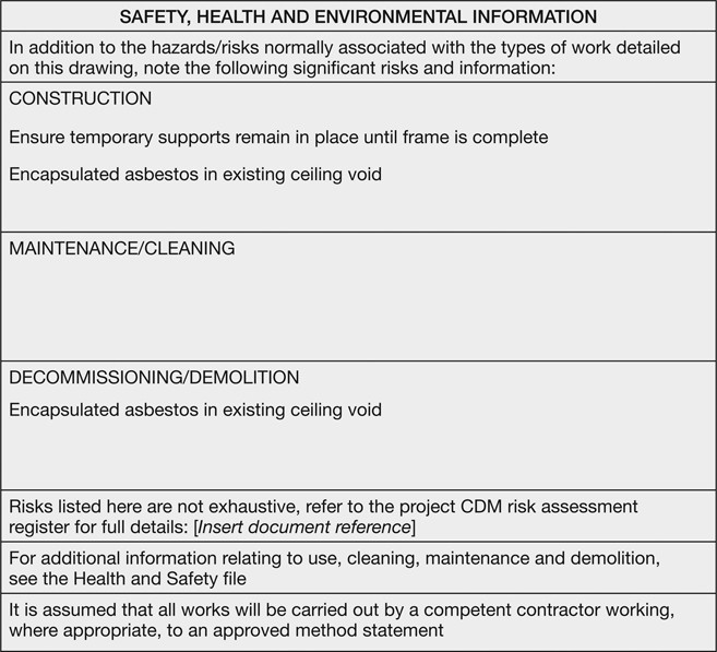
These strategies will inform and develop the status of the Project Information as the Technical Design is developed. The information protocols for this stage will be outlined within the Technology Strategy and the Communication Strategy, and will be closely aligned with the procurement strategy and Construction Strategy. This will ensure that the collaborative approach developed in the earlier design stages is maintained, irrespective of who produces the information. Any design input from specialist subcontractors will need to adhere to these protocols and standards to ensure that the quality and coordination of the design, including any key details and interfaces between design packages, can be coordinated and completed. The Project Information will be used extensively on site. Therefore, each ‘printed drawing’ offers considerable potential for communicating any residual health and safety risks outlined within the Project Strategies, including advice on finding further information, if required. Any member of the project team involved in producing design information for construction, should integrate this health and safety information with their published Project Information. A SHE (safety, health and environment) box (figure 4.1) can be used to communicate any residual risks relating to construction. The box can be added to the design information during the Developed Design or Technical Design stages, subject to reviews by the project team. The SHE box should summarise only significant outstanding issues: long generic lists should be avoided as they will tend to hide the more noteworthy issues. The SHE box information should be reviewed following the completion of construction and retained on any ‘As-constructed’ Information produced within Stages 5, 6 and 7. This will ensure that any remaining risks not mitigated by the contractor, especially those that are user or future maintenance related, are highlighted. Many specialist subcontractors use CAD, or perhaps BIM, to produce their information. However, as much of this information is produced solely for internal purposes, such as fabrication information, these aspects do not need to conform to the BS 1192:2007 standards and protocols. This does not necessarily affect the way the information is coordinated or utilised as often the design will be validated and checked by referencing the information into the design intent model files or by reviewing hard or soft copy ‘drawings’. However, for subcontractors developing a project using a BIM approach, utilising the project protocols and standards will be paramount to maintaining and developing the Project Information. It is likely that all the components within the design will be developed within the federated model, and while the output information won’t necessarily change, the design and interfaces of all the surrounding trades will need to be coordinated to the same level of definition as each different package is integrated. Each specialist subcontractor will need to understand the surrounding model elements and coordinate with them. Equally, these adjacent designs will need to have been finalised or developed in conjunction with the other specialist subcontractors. This implies that the scopes and procurement of all related packages will need to be aligned to ensure the Project Programme is maintained and that work is not continuously revisited as other inputs are developed.
Specialist subcontractors’ input to the BIM model Areas within the BIM model that require specialist subcontractor input, such as a curtain wall, could be created as a separate model and federated into the main design. This will allow the specialist subcontractor’s model to replace the design intent as it is developed, ensuring that:
In most design and build projects the production of information is managed to suit the Construction Programme. Often, specialist subcontractors are not appointed until they are required to progress the design. While this may accelerate the Design Programme activity, it does not benefit the collaborative development of Project Information. Often, a number of
critical interfaces will have to be redesigned to suit specialist subcontractor proposals developed in isolation. For example, the external cladding solution might be procured independently from the curtain walling and, if developed separately, late changes may be required to ensure they are successfully integrated with the coordinated design. BIM is a collaborative process and its benefits are derived from the project team working together to achieve an integrated solution. This approach will deliver efficiencies in programme, cost and quality within the final design, improving considerably on current practices. Reviewing the Design Responsibility Matrix as the implications of the sequencing and interfaces become clearer can allow for some of the key specialist subcontractors to be procured early in the Design Programme, to help minimise the design risks and benefit the overall design. The input required from specialist subcontractors will be outlined in the Design Responsibility Matrix during Stage 1 and may be updated prior to the Building Contract being awarded. As outlined in Stage 3, the required Project Information can be set out in a number of ways (see figure 4.2). The matrix allows the core responsibility to be identified, ie design team member or specialist subcontractor, and notes can be added to highlight key issues or interfaces between related trades and packages. The early appointment of specialist subcontractors can also ensure that the design is coordinated to improve maintainability and access. This will improve the management and operation of assets and systems during Stage 7. In particular, the actual performance and geometric details of each system can be defined within the PIM to allow the layout and location to be reviewed and the best approach to maintaining key elements developed accordingly. The procurement strategy, Project Programme and Design Responsibility Matrix define the requirements for any specialist subcontractor design, which is to be set out and managed using the project standards and protocols within the Project Execution Plan. The subsequent Project Information will be reviewed and verified in accordance with the design intent as issued by the design team. All comments on the quality and content of the information should be documented clearly, collated by the lead designer and circulated to provide feedback and direction to the
originator and other appropriate disciplines so that they also understand the impacts. Comments will typically be made by ‘marking up’ the issue directly on the drawing, schedule or specification. This can be completed manually on a printed copy or digitally within an editable PDF copy. If a common data environment (CDE), such as a web-based document management system, is being used this, subject to the system used, may also offer a ‘mark-up’ protocol for recording comments on the Project Information. In addition to the specific comments, the mark-up should also record the reviewer’s recommendation as to the status of the information, based on those set out in BS 1192:2007 and PAS 1192:2013. The process of marking up information can, if there are a number of details to comment on, tend to clutter the drawing sheet and confuse the message. To avoid misinterpretation, all the information applied in the mark-up should also be included on a separate document. This document will describe the full issue, including drawing number, revision, date of issue, each specific comment and the overall commented status. The comment sheet should be numbered as a project document accordingly and, most importantly, it will include the status definitions, if different from the British Standard, as used by the auditing discipline (see figure 4.3). A CDE should create a recorded copy of the information commented on, which will remain associated with the information throughout its use as a record of its development.
Status codes Both BS 1192:2007 Table 5, Standard codes for suitability models and documents, and PAS 1192-2:2013 Table 3, Status codes in the CDE, outline, some typical definitions for status codes (see Stage 3: Developed Design, figures 3.2 and 3.6). The BS 1192: definitions are:
The standard also notes that ‘All minor comments should be indicated by the insertion of a statement of “in abeyance” until the comment is resolved or minor changes incorporated and resubmitted to achieve full sign-off’. The PAS 1192-2: definitions are:
It is important to ensure that the originator of the information and its reviewer are aware of the overall process and the definition of each status. It is also likely that the reviewed information may not have been completely checked against all other systems and interfaces: in the majority of cases the originator will be responsible for finalising the information. The example comment sheet shown in figure 4.3 utilises a similar approach to the BS 1192 definitions, outlining the status as:
It also includes a number of caveats, which highlight the extent of the review completed. All ‘marked up’ information should provide a direct reference on the document, or a cross-reference to the document comment sheet, in order to maintain a link between the comment status and its definition and, therefore, the intent implied by the reviewer. This will avoid information progressing incorrectly and without coordination.
Chapter 4 summary
The success of the Technical Design stage will be dictated by the robustness of the Design Programme and Construction Programme. Sufficient time must be allowed for the completion of the tender information, the contractor’s appointment and the collaborative finalisation of the Project Information, including any specialist subcontractor input. The responsibility for the production of the Technical Design may change within this stage, especially following the appointment of the contractor. It is therefore important that all the information modelled, drawn, scheduled or specified is structured for development and coordination by any member of the project team, irrespective of process and software. Utilising the knowledge and skills of the contractor prior to their appointment and developing solutions with selected specialist subcontractors before the Building Contract is awarded will improve all aspects of the design. However, if the contractor is appointed before the design is finalised then it is likely that best value will be achieved through reviewing the programme and working collaboratively, to ensure that the Technical Design is completed prior to the start of Construction. This will reduce errors, save cost and time and improve the finished quality of the building. The Stage 4 Information Exchange is:
Additional information reviewed might include:
Introduction
What are the Core Objectives of this stage?

Providing the right information for construction
What information defines the Technical Design?
Drawn documentation
![]()
How does the specification support the Technical Design?
![]()
![]()
![]()
Types of specification
Prescriptive specifications
Descriptive specifications
Performance specifications
Technical specifications
![]()
What information describes the Technical Design?
![]()
Stage report
Location information
Assembly information
Component information
Schedules and reports
Additional Project Information
Specifications
What are the Information Exchanges at the end of Stage 4?
Developing key Project Strategies
What are the Key Support Tasks and Project Strategies?
How can the Health and Safety Strategy improve the Project Information?
How is a BIM project different for subcontractors?
![]()
What protocols should be used to review and verify information?
![]()