Chapter 2
Infrastructure Security and Segmentation
Chapter 1, “Let’s Talk About Network Security,” discusses the importance of identifying and securing the assets in your network. One of the most important assets is the network itself. If your network devices are compromised, then any data flowing through it will be compromised, too. This chapter discusses the security of the network infrastructure, including the three planes: management, control, and data.
This chapter also discusses the importance of segmenting traffic within a network as well as methods for doing so. Finally, this chapter lays a foundation for traffic analysis and security integration with a discussion on NetFlow and its security benefits.
The Three Planes
Yes, this is still a book on security! We did not leave the world of security for the astral planes, and neither did we switch to the flying kind. The planes we discuss here are the three that exist on a network device: the management, control, and data planes.
Any functions related to managing a device, such as configuring it, happen in the management plane. Access to this plane requires use of various protocols, such as SSH, Telnet, SNMP, and SFTP. This is the most important plane in terms of securing a device because any breach on this plane will allow access to all data flowing through the device and even the ability to reroute traffic.
In the control plane, the device discovers its environment and builds the foundation to do its job. For example, a router uses routing protocols in the control plane to learn about the various routes. Routes allow a router to do its primary job—route packets. A switch uses protocols such as VTP and STP to learn about various paths, and that allows it to switch traffic. If the protocols in the control plane are not secured, a malicious actor may be able to inject rogue control packets and influence the path of the packets. For example, if your routing protocols are not secure, then it is possible to inject rogue routes, causing data to flow to a different device. This technique is often used in man- in-the-middle (MITM) attacks.
The data plane, also called the forwarding plane, is where the actual data flows. When a router receives a packet to route or a switch receives a frame to switch, it does so on the data plane. Information learned in the control plane facilitates the functions of the data plane. Typically, this is where most of the network security controls are focused. Packet filtering, protocol validation, segmentation, malicious traffic detection, distributed denial-of-service (DDoS) protection, and other security measures are utilized in this plane.
In addition to the three planes, the physical security of a device itself is important. After all, the security in the software does not matter if the hardware is compromised. While it is the responsibility of the vendor—Cisco in this case—to ensure that a device is not tampered with between manufacturing and your doorstep, it is your responsibility to ensure that the devices are kept in a secure location where unauthorized access can be prevented.
The three planes and physical security can be visualized as the pyramid shown in Figure 2-1, where compromise on one layer will affect all the layers above it.
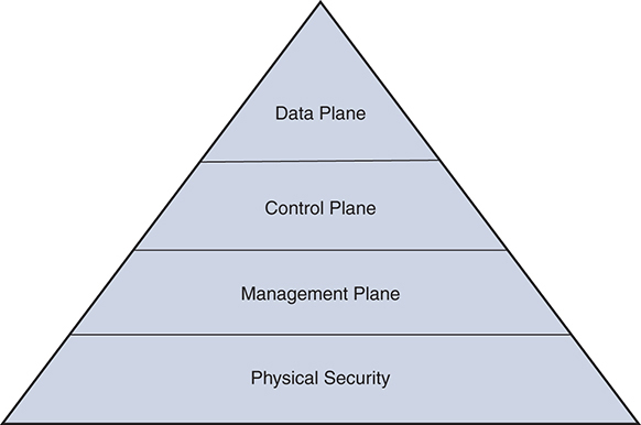
Figure 2-1 The Pyramid of Planes
Securing the Management Plane
Any function related to management of a device resides in the management plane. The primary means of managing Cisco routers and switches are the console and the vty. Both of these provide access to the command-line interface (CLI). In most cases, even when a GUI interface for management is available, it uses the CLI to issue commands to the device. Apart from direct access to the CLI, SNMP can be used for information gathering and change configuration.
Other noteworthy functions that reside in this plane relate to logging and time management. In this section, we discuss security of the CLI and SNMP. Before we discuss the specific topics, some of the general security practices associated with the management plane should be understood:
![]() Zero trust and minimum required access: Network devices are the backbone of your information technology infrastructure and should have very strict and restrictive access control applied. Few selected and trained individuals should have access to network devices, and their activities on devices should be authorized and logged. Centralized access control using an authentication, authorization, and accounting (AAA) server along with command authorization are highly recommended. While this chapter briefly discusses AAA, an entire chapter in Integrated Security Technologies and Solutions, Volume II covers it in depth.
Zero trust and minimum required access: Network devices are the backbone of your information technology infrastructure and should have very strict and restrictive access control applied. Few selected and trained individuals should have access to network devices, and their activities on devices should be authorized and logged. Centralized access control using an authentication, authorization, and accounting (AAA) server along with command authorization are highly recommended. While this chapter briefly discusses AAA, an entire chapter in Integrated Security Technologies and Solutions, Volume II covers it in depth.
![]() Central monitoring and log collection: Logs from network devices provide important event and performance data. They should be collected, analyzed, and correlated in a central location for preventive measures as well as incidence response. Similarly, monitoring the network devices using SNMP provides a constant view of the network security and performance while reducing the need for logging in to the device directly.
Central monitoring and log collection: Logs from network devices provide important event and performance data. They should be collected, analyzed, and correlated in a central location for preventive measures as well as incidence response. Similarly, monitoring the network devices using SNMP provides a constant view of the network security and performance while reducing the need for logging in to the device directly.
![]() Secure communication: Multiple protocols can be used to access network devices for management. The devices should be configured to use only secure protocols. For example, SSH, HTTPS, and SFTP provide encrypted transfer, whereas Telnet, HTTP, and FTP do not. Similarly, SNMP Version 3 (SNMPv3) should be used instead of earlier versions to provide secure and authenticated access.
Secure communication: Multiple protocols can be used to access network devices for management. The devices should be configured to use only secure protocols. For example, SSH, HTTPS, and SFTP provide encrypted transfer, whereas Telnet, HTTP, and FTP do not. Similarly, SNMP Version 3 (SNMPv3) should be used instead of earlier versions to provide secure and authenticated access.
![]() Central configuration management: Using centralized configuration management provides change versioning and archiving while also keeping your policies consistent across the network.
Central configuration management: Using centralized configuration management provides change versioning and archiving while also keeping your policies consistent across the network.
![]() Disabling unnecessary services: Routers and switches contain many services that listen for packets. Services that are not required on your network should be disabled to prevent the chance that they will be used to launch an attack on the device. Special attention should be paid to what Cisco calls small servers. These are disabled by default but can be enabled by using the service tcp-small-servers and service udp-small-servers commands.
Disabling unnecessary services: Routers and switches contain many services that listen for packets. Services that are not required on your network should be disabled to prevent the chance that they will be used to launch an attack on the device. Special attention should be paid to what Cisco calls small servers. These are disabled by default but can be enabled by using the service tcp-small-servers and service udp-small-servers commands.
Securing the Command Line
The Cisco IOS CLI is divided into 16 privilege levels, each of which defines what commands are available to a user. The privilege levels are divided into four categories:
![]() Privilege level 0: Includes the disable, enable, exit, help, and logout commands.
Privilege level 0: Includes the disable, enable, exit, help, and logout commands.
![]() User EXEC mode: Also called privilege level 1. By default, users log in to this mode, and it is denoted by a greater-than sign (>) at the end of the prompt. Commands available in this level cannot affect the device configuration.
User EXEC mode: Also called privilege level 1. By default, users log in to this mode, and it is denoted by a greater-than sign (>) at the end of the prompt. Commands available in this level cannot affect the device configuration.
![]() Privileged EXEC mode: Also called privilege level 15. This level can be entered by using the enable command in the user EXEC mode and is denoted by the hash sign (#) at the end of the prompt. All commands are available at this level.
Privileged EXEC mode: Also called privilege level 15. This level can be entered by using the enable command in the user EXEC mode and is denoted by the hash sign (#) at the end of the prompt. All commands are available at this level.
![]() Custom privileged modes: Whereas level 1 provides no access to configuration, level 15 provides full access to it. In some cases, neither of these levels can fulfill the requirements of access control policies. To provide tailored access control, IOS has privilege levels 2 to 14. By default, these levels do not provide any more access than level 1 but can be configured to provide access to required commands.
Custom privileged modes: Whereas level 1 provides no access to configuration, level 15 provides full access to it. In some cases, neither of these levels can fulfill the requirements of access control policies. To provide tailored access control, IOS has privilege levels 2 to 14. By default, these levels do not provide any more access than level 1 but can be configured to provide access to required commands.
Each of these privilege levels can be protected by passwords. The first level is protected by the passwords configured in the terminal lines. Different devices have different numbers of lines that can be ascertained with the show line command. Typically, Cisco switches and routers have 1 console line and 16 vty lines. You can configure a password to protect the lines by using the password command on the terminal lines as shown in Example 2-1.
Example 2-1 Configuring Passwords on Terminal Lines
R1#configure terminal
Enter configuration commands, one per line.  End with CNTL/Z.
R1(config)#line vty 0 15
R1(config-line)#password L3tm31n!
R1(config-line)#exit
R1(config)#line console 0
R1(config-line)#password L3tm31n!
R1(config-line)#
In addition to the password, the vty lines should be configured to use SSH instead of Telnet to allow for encrypted communication with the device. Before SSH can be enabled on the vty lines, an SSH key must be generated on the device, as shown in Example 2-2.
Example 2-2 Generating an SSH Key
R1(config)#ip domain-name cisco.com
R1(config)#crypto key generate rsa modulus 2048
After the SSH key is generated, the vty lines can be configured to use SSH only. To do this, use the transport input command, as shown in Example 2-3.
Example 2-3 Changing the Transport Protocols on vty Lines
R1(config)#line vty 0 15
R1(config-line)#transport input ssh
R1(config-line)#exit
vty lines can be further secured by applying an access list such that SSH sessions are accepted only from certain IP addresses or ranges. This requires an access list that contains the allowed IP addresses. That access list can be applied to vty lines using the access-class command, as shown in Example 2-4.
Example 2-4 Using an ACL to Restrict Access to vty Lines
R1(config)#access-list 1 permit host 192.168.1.10
R1(config)#access-list 1 permit host 192.168.1.15
R1(config)#line vty 0 15
R1(config-line)#access-class 1 in
The line mode provides some other commands that can be used to secure terminal access. Some of the most important ones are discussed here:
![]() autocommand: This command is used to configure the lines to execute a specific command when a remote access session is established and authenticated. The session disconnects after execution is completed. The command to be executed is specified as the argument in this case. In Example 2-5, the lines are configured to execute show running-config as soon as the SSH session is established. The SSH session is disconnected after the configuration is displayed.
autocommand: This command is used to configure the lines to execute a specific command when a remote access session is established and authenticated. The session disconnects after execution is completed. The command to be executed is specified as the argument in this case. In Example 2-5, the lines are configured to execute show running-config as soon as the SSH session is established. The SSH session is disconnected after the configuration is displayed.
Example 2-5 Executing a Command on Session Establishment
R1(config)#line vty 0 15
R1(config-line)#privilege level 15
R1(config-line)#autocommand show running-config
![]() exec-timeout: This command configures the duration, in minutes, for which an idle session will be kept alive. It is important to configure a short duration to safeguard against unauthorized access as well as to prevent all vty lines from being used up by idle sessions. Example 2-6 shows how this is configured.
exec-timeout: This command configures the duration, in minutes, for which an idle session will be kept alive. It is important to configure a short duration to safeguard against unauthorized access as well as to prevent all vty lines from being used up by idle sessions. Example 2-6 shows how this is configured.
Example 2-6 Configuring the Idle Timeout
R1(config)#line vty 0 15
R1(config-line)#exec-timeout 5
![]() privilege level: This command configures the default privilege level that the user lands into after an access session is established on the terminal lines. By default, a user starts at privilege level 1, but that can be changed to any level, including 15. In Example 2-7, the default privilege level for the console line is configured to be 15. After this, when a user connects to the console and authenticates successfully, she starts in privilege level 15 instead of 1.
privilege level: This command configures the default privilege level that the user lands into after an access session is established on the terminal lines. By default, a user starts at privilege level 1, but that can be changed to any level, including 15. In Example 2-7, the default privilege level for the console line is configured to be 15. After this, when a user connects to the console and authenticates successfully, she starts in privilege level 15 instead of 1.
Example 2-7 Configuring the Default Privilege Level
R1(config)#line con 0
R1(config-line)#privilege level 15
Privilege Levels
After successful authentication using the line password, a user enters privilege level 1 by default. If the user needs to access a higher level, he needs to use the enable [level] command and enter the enable password associated with that level. This password is configured using the enable secret [level] command. If a level is not specified with either of the commands, level 15 is assumed. Example 2-8 shows how the secrets for different levels are configured. The first example does not specify a level; hence, it is assumed to be for level 15. Example 2-9 shows how the enable command is used to enter different levels. Note the use of the show privilege command to show the level that the user is in and the disable [level] command to go back to a previous level. The default level for the disable command is 1.
Example 2-8 Configuring enable secret
R1(config)#enable secret cisco123!
R1(config)#enable secret level 5 l3v3l5!
R1(config)#enable secret level 10 l3v3l10!
Example 2-9 Changing IOS Levels
R1>enable
Password:
R1#show privilege
Current privilege level is 15


R1#disable
R1>show privilege
Current privilege level is 1


R1>enable 5
Password:
R1#show privilege
Current privilege level is 5


R1#disable
R1>enable
Password:
R1#show privilege
Current privilege level is 15


R1#disable 10
R1#show privilege
Current privilege level is 10
All custom levels from 2 to 14 are no different from level 1 to start with. All configuration commands and most verification commands have a default level of 15. To populate the custom levels, you need to reduce the level of required commands from 15 to the desired level. This can be done with the privilege command, which has the following syntax:
privilege mode level level command-string
The mode string denotes the mode in which the command is available—such as configuration, interface, or exec. IOS has hundreds of modes. Usually the name of the mode is reflected in the command used to enter that mode.
The level string denotes the new level of the command. This is the custom level in which you want the command to be available.
The command-string option specifies the actual command that is subject to privilege level change.
As an example, if you want the show running-config command to be available at level 5, you need to reduce the privilege level of that command to 5, as shown in Example 2-10.
Example 2-10 Changing Privilege Levels of Commands
R1#show privilege
Current privilege level is 5


R1#show run?
% Unrecognized command


R1#enable
Password:
R1#config t
Enter configuration commands, one per line.  End with CNTL/Z.


R1(config)#privilege exec level 5 show running-config
R1(config)#exit
R1#disable 5
R1#show privilege
Current privilege level is 5


R1#show running-config
Building configuration…
Using custom privilege levels is an easy way to provide differentiated access based on job roles. This is particularly useful in allowing help-desk members to perform basic maintenance functions on a network device while preventing them from making changes to the overall configuration of the device. Example 2-11 shows how privilege level 10 is given the ability to shut down an interface or bring one up without allowing users in that level to make any other changes. Note the use of the mode names—exec, configure, and interface—with the privilege command. The mode name denotes the mode in which the subject command is available.
Example 2-11 Changing Privilege Levels of Configuration Commands
R1#show privilege
Current privilege level is 10
R1#configure terminal
             ^
% Invalid input detected at ‘^’ marker.


R1#enable
Password:
R1#config t
Enter configuration commands, one per line.  End with CNTL/Z.


R1(config)#privilege exec level 10 configure terminal
R1(config)#privilege configure level 10 interface
R1(config)#privilege interface level 10 shutdown
R1(config)#exit


R1#disable 10
R1#configure terminal
Enter configuration commands, one per line.  End with CNTL/Z.
R1(config)#interface Gi0/1
R1(config-if)#shut?
shutdown
While using local passwords and privilege levels on the device provides the required security, it can be cumbersome to manage these on each device, and inconsistent configuration across the network is very likely. To simplify device configuration and maintain consistency, it is recommended that you use an AAA server such as Cisco Identity Services Engine (ISE). The network devices can use the Terminal Access Controller Access Control System Plus (TACACS+) protocol to authenticate users and authorize commands. Since the authorization configuration is centralized on the AAA server, policies are applied consistently across all network devices. AAA servers and their use for securing CLI access are discussed in depth in Integrated Security Technologies and Solutions, Volume II.
Management Plane Protection
Earlier in this chapter, we discussed the use of an access list to limit the source addresses from which remote access sessions are accepted on vty lines. While the ACL limits the source addresses, recommended best practice is to limit remote management sessions to specific trusted interfaces only.
The Management Plane Protection (MPP) feature can be used to limit remote management sessions to specific trusted interfaces only. This is very useful when a router connects a trusted network to an untrusted network such as the Internet. MPP applies to all management protocols, such as SSH, HTTPS, and SNMP. This feature is configured using the management-interface command in the control pane. This command can be repeated to enable the same or a different set of protocols on other interfaces. One key restriction of this feature is that it cannot be applied to an out-of-band management interface (also called a dedicated management interface), if the device has one. Example 2-12 shows the usage of this command.
Example 2-12 Management Plane Protection
R1(config)#control-plane host
R1(config-cp-host)#management-interface Gi0/0 allow ssh snmp https
CPU and Memory Thresholding
When a network device is under a denial-of-service (DoS) attack, its resources such as CPU and memory start to deplete quickly. Hence, it is important to monitor the resources on your network devices. While regular polling of devices using SNMP helps, configuring a device to send an SNMP trap when certain CPU and memory utilization thresholds have been reached is better. The CPU and Memory Threshold notification features provide this functionality.
The CPU Thresholding Notification feature can alert when CPU utilization exceeds a configured level and when the utilization drops below a configured level. The former is called a rising notification, and the latter is called a falling notification.
The syntax for the command to enable CPU thresholding notification is as follows:
process cpu threshold type {total|process|interrupt} rising percentage interval
seconds [falling percentage interval seconds]
In addition to this command, SNMP traps for CPU threshold must be enabled. Example 2-13 shows the configuration required to enable CPU thresholding notification.
Example 2-13 CPU Thresholding Notification
R1(config)#snmp-server enable traps cpu threshold
R1(config)#snmp-server host 192.168.1.25 traps version 3 priv vuser cpu
R1(config)#process cpu threshold type process rising 85 interval 60 falling  60 interval 60
Similarly, memory thresholding notification can be configured to provide notification when available free memory drops below a certain level and when it rises higher than 5% of that level. In addition, you can configure the device to reserve some memory to send out critical notifications.
This is the syntax for the command to configure the notification:
memory free low-watermark {IO|processor} threshold
This is the syntax for the command to configure memory reservation:
memory reserve critical memory
In these commands, threshold and memory are specified in kilobytes. Example 2-14 shows the configuration required to enable memory threshold notification and critical memory reservation.
Example 2-14 Memory Threshold Notification
R1(config)#memory free low-watermark processor 25000
R1(config)#memory reserve critical 5000
Securing SNMP
SNMP is incredibly useful for monitoring network devices. It can also be used to make changes to devices remotely. This also brings with it risk of misuse and opens up an attack avenue. Hence, it is important to secure SNMP access on your network devices. There are multiple ways to do that, as discussed in the following sections, and Cisco recommends using all these methods together.
SNMP Authentication and Encryption
Three versions of SNMP can be configured on Cisco routers and switches: Versions 1, 2c, and 3. Versions 1 and 2c use simple community strings to provide read-only or read-write access. Community strings can be equated to passwords and are stored in the configuration in plaintext. Communications between the SNMP servers and clients are in plaintext and are prone to snooping.
On the other hand, SNMPv3 allows using usernames and a hash message authentication code (HMAC), and it can encrypt the traffic. SNMPv3 user details are not shown in configuration. SNMPv3 has three levels of operations:
![]() noAuthNoPriv: Uses username for authentication with no HMAC or encryption. Very similar to how Version 1 and Version 2c work.
noAuthNoPriv: Uses username for authentication with no HMAC or encryption. Very similar to how Version 1 and Version 2c work.
![]() authNoPriv: Uses username with MD5 or SHA HMAC for authentication.
authNoPriv: Uses username with MD5 or SHA HMAC for authentication.
![]() authPriv: Uses username with HMAC for authentication and provides encryption based on DES, 3DES, or AES.
authPriv: Uses username with HMAC for authentication and provides encryption based on DES, 3DES, or AES.
Given the security benefits, SNMPv3 should be preferred over older versions. Where SNMPv3 is not available, the community strings should be changed from the defaults. One of the most common SNMP strings is “public,” and that is typically the first string used by an attacker.
Table 2-1 lists the differences between the various versions of SNMP.
Table 2-1 SNMP Versions and Their Security
SNMP Version and Level |
Security |
Credentials Visible in Configuration? |
1 |
Community string |
Yes |
2c |
Community string |
Yes |
3 (noAuthNoPriv) |
Username |
Yes |
3 (authNoPriv) |
HMAC |
No |
3 (authPriv) |
HMAC with encryption |
No |
When configuring SNMPv3, users are tied to groups and SNMP traps. All SNMP server and trap configuration is then tied to the user. The commands to create groups and users are shown here:
snmp-server group group-name v3 {auth|noauth|priv}
snmp-server user username group-name v3 auth {md5|sha} password [priv {3des|aes 128|aes 192|aes 256|des} encryption-key]
Example 2-15 shows how SNMPv3 groups and users are created and then applied to host configuration.
Example 2-15 SNMPv3 Configuration
R1(config)#snmp-server group snmpl33t v3 priv
R1(config)#snmp-server user l33t snmpl33t v3 auth sha gu3$$myPa$$ priv aes 256 3ncryp1!
R1(config)#snmp-server host 192.168.1.25 traps version 3 priv l33t
SNMP with Access Lists
While authentication and encryption provide a high degree of security, SNMP access should be further restricted with an access list. Access lists can be applied to an SNMP group to limit the source address from which an SNMP read or write request will be received.
To apply an access list to a group, the previously discussed snmp-server group command is extended as shown here:
snmp-server group group-name v3 {auth|noauth|priv} access access-list
Example 2-16 shows how an access list is added to an SNMP group to allow SNMP queries from a known network management server only.
Example 2-16 Adding an Access List to an SNMP Group
R1(config)#access-list 1 permit 192.168.1.25
R1(config)#snmp-server group snmpl33t v3 priv access 1
SNMP Views
The SNMP server on Cisco devices allows access to the whole MIB tree by default. Using authentication, encryption, and IP-based access restriction provides good security, but it can be further enhanced by restricting the MIBs that can be accessed. SNMP views provide the ability to define what MIBs an SNMP group has access to. A view is a list of MIBs that are included or excluded. The following command creates a view:
snmp-server view view-name mib-name-or-oid {included|excluded}
After a view is created, you can apply it to the SNMP group by extending the previously discussed snmp-server group command as shown here:
snmp-server group group-name v3 {auth|noauth|priv} [read view-name]
[write view-name] [access access-list]
Example 2-17 shows how to configure a view and apply it to an SNMP group with an access list.
Example 2-17 Adding a View to an SNMP Group
R1(config)#access-list 1 permit 192.168.1.25
R1(config)#snmp-server view limited system included
R1(config)#snmp-server group snmpl33t v3 priv read limited write limited access 1
Securing the Control Plane
The control plane is where a Cisco switch or router learns about its environment, using various protocols to talk to neighboring devices. The protocols operating on the control plane of a router are different from those of a switch. Therefore, the types of attacks and the intended results are also different, but they can be generalized into two broad sets:
![]() Overwhelming the control plane: This is a DoS attack in which an attempt is made to overwhelm the CPU by sending a large number of control packets. When the CPU is busy handling this flood, it isn’t able to process normal traffic.
Overwhelming the control plane: This is a DoS attack in which an attempt is made to overwhelm the CPU by sending a large number of control packets. When the CPU is busy handling this flood, it isn’t able to process normal traffic.
![]() Corrupting control plane data: In this type of attack, malicious control plane protocol packets are used to inject rogue information to affect the actual flow of data. Typically, STP, VTP, and routing protocols are used in the control plane to create routing tables, forwarding tables, and other tables. An attacker managing to inject incorrect information in these tables can result in a DoS attack or, worse, the data can be redirected to a rogue device for a MITM attack.
Corrupting control plane data: In this type of attack, malicious control plane protocol packets are used to inject rogue information to affect the actual flow of data. Typically, STP, VTP, and routing protocols are used in the control plane to create routing tables, forwarding tables, and other tables. An attacker managing to inject incorrect information in these tables can result in a DoS attack or, worse, the data can be redirected to a rogue device for a MITM attack.
There are two ways to protect the control plane. The first is to secure each protocol used on this plane, and the second is to police the traffic arriving at it. While the mechanisms used to secure various protocols differ, policing the traffic is done using a feature called Control Plane Policing (CoPP). The next section discusses CoPP, and the two sections after that discuss the security of the protocols most commonly used at this plane on switches and routers.
Control Plane Policing (CoPP)
The CoPP feature on a Cisco device does exactly what it sounds like: It polices the traffic coming to the control plane. For this purpose, the control plane is treated as a logical source and destination, with its own inbound and outbound interfaces. Only traffic that is destined for the control plane is policed as part of this feature. This is in addition to any policing, filtering, or any other processing done at the interface where the packet was received by the device.
Examples of packets that get routed to the control plane are routing protocol packets, STP and VTP packets, and packets destined to any of the IP addresses of the device, including those of management plane protocols.
CoPP is configured almost the same way as quality of service (QoS) on any interface, with the difference being that the service policy is applied to the control plane. A detailed discussion of QoS is beyond the scope of this book, but as a refresher, the Modular QoS CLI (MQC) is used to configure QoS, which can be divided into three steps:
Step 1. Defining the traffic: In the first step, the interesting traffic is defined in a class map. A common method of defining interesting traffic is to create an access list and reference it in a class map, as shown in Example 2-18. This example creates a class map for all BGP and SSH traffic.
Example 2-18 Defining a Class Map for QoS
R1(config)#access-list 100 permit tcp any any eq bgp
R1(config)#access-list 100 permit tcp any any eq ssh
R1(config)#class-map copp_class
R1(config-cmap)#match access-group 100
Step 2. Defining a service policy: In this step, the actual QoS policy and associated actions are defined in a policy map. For CoPP, police is the only valid QoS option. Example 2-19 shows a policing policy applied to the CoPP class map created in the previous example. In this example, the QoS policy is configured to police all BGP and SSH traffic to 300 kbps and to drop any traffic that exceeds this rate.
Example 2-19 Defining a Service Policy
R1(config)#policy-map copp_policy
R1(config-pmap)#class copp_class
R1(config-pmap-c)#police 300000 conform-action transmit exceed-action drop
Step 3. Applying the service policy: The last step is to apply the service policy to the correct interface. Normally, the policy is applied to an interface, but in the case of CoPP, it is applied in the control plane configuration mode, as shown in Example 2-20.
Example 2-20 Applying CoPP Service Policy
R1(config)#control-plane
R1(config-cp)#service-policy input copp_policy
Securing Layer 2 Control Plane Protocols
A Layer 2 network can be very complex and requires various protocols to run efficiently. Of these protocols, Spanning Tree Protocol (STP) and VLAN Trunking Protocol (VTP) are the most important. While an in-depth discussion of STP and VTP is beyond the scope of this book, this section examines the core functioning of the protocols, their inherent weaknesses, and how to secure them.
Securing Spanning Tree Protocol (STP)
While redundant links are a necessity for a Layer 2 network, they can cause broadcast frames to loop around the network. Since Ethernet frames do not have a time to live (TTL), the frames can loop forever and eventually bring down the network. STP was created to resolve this by allowing redundant links to be in a blocked state until they are needed.
To understand the inherent weakness in STP, it is important to know how it works. STP forms a tree-like topology with the root bridge at the base. The root bridge is elected based on data shared in bridge protocol data units (BPDUs). BPDU frames are sent to well-known multicast addresses and contain, among other information, the switch’s MAC address and a user-defined priority value. A combination of these values is called the bridge ID, and the switch with the lowest ID is elected the root bridge.
After a root bridge is elected, each switch in the domain finds the interface that leads to the best path toward the root bridge and designates it as the root port, while redundant links are placed in a blocked mode. All active interfaces on a switch will be in either forwarding mode or blocked mode at the end. This process is called convergence. Figure 2-2 shows a topology after normal STP convergence. In this figure, traffic from WS-1 to WS-2 will take the path from SW-A to the root bridge, SW-B, on the way to SW-D. Notice that the path between SW-A and SW-C is blocked because it is redundant to the path between SW-A and SW-B.
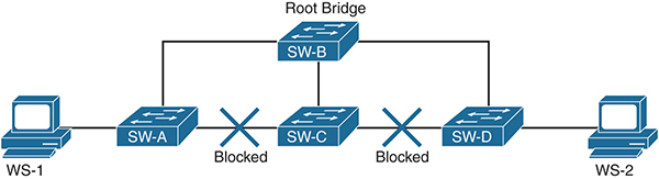
Figure 2-2 Network During Normal STP Operations
Changes to topology, addition of new switches, and other similar events can cause a new root bridge to be elected and the STP domain to go through convergence. The time it takes to finish the process is significant, and no traffic is forwarded during that time.
Note The original STP was defined in the IEEE 802.1d standard and had a high convergence time. IEEE 802.1w was later introduced as Rapid STP, which has a much lower convergence time.
In addition to the forwarding disruption during convergence, STP has absolutely no security built into it. BPDUs are exchanged in plaintext, and there is no authentication mechanism. A switch trusts and uses whatever BPDU frames it receives. Given this information, it is easy to understand that STP can be exploited in multiple ways:
![]() DoS attacks: By sending out crafted BPDUs, it is not difficult to assume a root bridge role in the STP domain, thereby causing a significant part of traffic to be switched to a rogue machine instead of the actual destinations. Even if the root bridge role is not assumed, sending out BPDUs with topology change notifications in short intervals can cause traffic disruption by forcing convergence repeatedly.
DoS attacks: By sending out crafted BPDUs, it is not difficult to assume a root bridge role in the STP domain, thereby causing a significant part of traffic to be switched to a rogue machine instead of the actual destinations. Even if the root bridge role is not assumed, sending out BPDUs with topology change notifications in short intervals can cause traffic disruption by forcing convergence repeatedly.
![]() MITM attacks: In certain cases, a rogue device can advertise a low bridge ID and become the root bridge. This causes a significant part of traffic to be switched toward it, where it can be copied, modified, and forwarded to the actual destination. To illustrate this, Figure 2-3 shows what happens when a malicious user is able to form a trunk to SW-A and SW-C, in the previous example, and become the root bridge by advertising a lower bridge ID. Now the path between SW-A and SW-B is also blocked. All traffic between WS-1 and WS-2 will now flow through the malicious root bridge WS-R, where it can be intercepted and modified before being forwarded on.
MITM attacks: In certain cases, a rogue device can advertise a low bridge ID and become the root bridge. This causes a significant part of traffic to be switched toward it, where it can be copied, modified, and forwarded to the actual destination. To illustrate this, Figure 2-3 shows what happens when a malicious user is able to form a trunk to SW-A and SW-C, in the previous example, and become the root bridge by advertising a lower bridge ID. Now the path between SW-A and SW-B is also blocked. All traffic between WS-1 and WS-2 will now flow through the malicious root bridge WS-R, where it can be intercepted and modified before being forwarded on.
Figure 2-3 Network After a MITM Attack with STP
STP itself does not have any security mechanism, but three methods can be used to mitigate the risk on Cisco switches:
![]() Disabling Dynamic Trunking Protocol (DTP): Cisco switches use a proprietary protocol, DTP, to automatically negotiate trunking between two switches. It is enabled on all interfaces by default and can be easily exploited to create unauthorized trunk links. Trunk links are special because they can send traffic on multiple VLANs. Hence, DTP should be disabled on all interfaces, and trunking should be configured manually where required. To disable DTP use the switchport nonegotiate command on all interfaces. In addition, all interfaces where trunking is not required should be configured to be in the access mode with the command switchport mode access. Example 2-21 shows the configuration required on interfaces to disable DTP and manually configure it to be in the access mode.
Disabling Dynamic Trunking Protocol (DTP): Cisco switches use a proprietary protocol, DTP, to automatically negotiate trunking between two switches. It is enabled on all interfaces by default and can be easily exploited to create unauthorized trunk links. Trunk links are special because they can send traffic on multiple VLANs. Hence, DTP should be disabled on all interfaces, and trunking should be configured manually where required. To disable DTP use the switchport nonegotiate command on all interfaces. In addition, all interfaces where trunking is not required should be configured to be in the access mode with the command switchport mode access. Example 2-21 shows the configuration required on interfaces to disable DTP and manually configure it to be in the access mode.
Example 2-21 Disabling DTP and Trunking on an Interface
SW1(config)#interface Gi0/5
SW1(config-if)#switchport mode access
SW1(config-if)#switchport nonegotiate
Note Disabling DTP on interfaces and statically configuring non-trunk interfaces as access ports are the most important security measures that you can take for your Layer 2 network. These measures alone mitigate risks associated with various protocols, such as LACP, VTP, and STP.
![]() Enabling BPDU Guard: BPDUs are generated and consumed by network switches. They should never be accepted on interfaces that do not connect other switches. Unfortunately, by default, a switch consumes BPDUs received on any interface, including those that connect to end-user devices such as workstations and printers. This can be prevented with a security feature called BDPU Guard. Where enabled, it shuts down an interface if BPDUs are received on it. BPDU Guard can be configured globally or on a per-interface basis. When configured globally, it is only enabled on ports configured as PortFast edge (or simply PortFast on older switch codes). Example 2-22 shows how BDPU Guard is enabled globally while Example 2-23 shows how it is enabled on a per-interface basis.
Enabling BPDU Guard: BPDUs are generated and consumed by network switches. They should never be accepted on interfaces that do not connect other switches. Unfortunately, by default, a switch consumes BPDUs received on any interface, including those that connect to end-user devices such as workstations and printers. This can be prevented with a security feature called BDPU Guard. Where enabled, it shuts down an interface if BPDUs are received on it. BPDU Guard can be configured globally or on a per-interface basis. When configured globally, it is only enabled on ports configured as PortFast edge (or simply PortFast on older switch codes). Example 2-22 shows how BDPU Guard is enabled globally while Example 2-23 shows how it is enabled on a per-interface basis.
Example 2-22 Enabling BPDU Guard Globally
SW1(config)#interface Gi0/5
SW1(config-if)#spanning-tree portfast edge
SW1(config-if)#exit
SW1(config)#spanning-tree portfast edge bpduguard default
Example 2-23 Enabling BPDU Guard on a Per-Interface Basis
SW1(config)#interface Gi0/5
SW1(config-if)#spanning-tree portfast edge
SW1(config-if)#spanning-tree bpduguard enable
Note In older switch codes, the edge keyword in PortFast commands is not used. Remove the edge keyword from the commands if you are practicing on older codes. Be sure of the proper command based on the IOS versions published in the CCIE blueprint.
![]() Enabling BPDU Filter: Whereas BPDU Guard is applied to incoming frames, BPDU Filter prevents BPDUs from being sent and received on an interface. This is useful in preventing users from gathering information about the network while also blocking unauthorized BPDUs. Much like BDPU Guard, this feature can be enabled globally on all PortFast-enabled interfaces or on a per-interface basis. Example 2-24 shows the global configuration, and Example 2-25 shows how BPDU Filter is enabled on a per-interface basis.
Enabling BPDU Filter: Whereas BPDU Guard is applied to incoming frames, BPDU Filter prevents BPDUs from being sent and received on an interface. This is useful in preventing users from gathering information about the network while also blocking unauthorized BPDUs. Much like BDPU Guard, this feature can be enabled globally on all PortFast-enabled interfaces or on a per-interface basis. Example 2-24 shows the global configuration, and Example 2-25 shows how BPDU Filter is enabled on a per-interface basis.
Example 2-24 Enabling BPDU Filter Globally
SW1(config)#interface Gi0/5
SW1(config-if)#spanning-tree portfast edge
SW1(config-if)#exit
SW1(config)#spanning-tree portfast edge bpdufilter default
Example 2-25 Enabling BPDU Filter on a Per-Interface Basis
SW1(config)#interface Gi0/5
SW1(config-if)#spanning-tree portfast edge
SW1(config-if)#spanning-tree bpdufilter enable
Securing VLAN Trunking Protocol (VTP)
Using VLANs for segmentation of traffic is a common method for optimizing a network and security. For VLANs to work properly, they should be created consistently across the network. Incorrect VLAN configuration can result in undesired results, such as connectivity problems. VTP can be used to create and maintain a consistent VLAN database. When VTP is implemented, the switches participate as a server or a client. VLANs are created and modified on the VTP server, and replicated to VTP clients. All switches configured as VTP clients create and modify VLANs locally based on the received data. A VTP client does not allow manual local changes to the VLAN database.
Before looking at the security implications of VTP, it is important to understand some key definitions:
![]() VTP domain: A VTP domain is a logical grouping of switches that share a VLAN database. The domain name in a VTP update should match the domain configured on the switch. The update will be dropped if the domain names do not match.
VTP domain: A VTP domain is a logical grouping of switches that share a VLAN database. The domain name in a VTP update should match the domain configured on the switch. The update will be dropped if the domain names do not match.
![]() VTP server: A switch can operate in three VTP modes: server, client, and transparent. The server is the single source of truth, and all changes are made to it. Each change is replicated on the clients through an update sent by the server.
VTP server: A switch can operate in three VTP modes: server, client, and transparent. The server is the single source of truth, and all changes are made to it. Each change is replicated on the clients through an update sent by the server.
![]() VTP client: Most switches participate as VTP clients. When they receive an update, they verify the domain name and make changes to the local VLAN database.
VTP client: Most switches participate as VTP clients. When they receive an update, they verify the domain name and make changes to the local VLAN database.
![]() VTP transparent: A switch in the VTP transparent mode does not participate in a VTP domain but forwards all updates out its trunk interface. A switch in this mode maintains its own VLAN database and allows local manual changes.
VTP transparent: A switch in the VTP transparent mode does not participate in a VTP domain but forwards all updates out its trunk interface. A switch in this mode maintains its own VLAN database and allows local manual changes.
![]() Revision number: The VTP revision number allows you to maintain version information of the VLAN database. A client does not use an update unless it has a higher revision number than that of the current local database.
Revision number: The VTP revision number allows you to maintain version information of the VLAN database. A client does not use an update unless it has a higher revision number than that of the current local database.
![]() VTP version: VTP has three versions: 1, 2, and 3. While Versions 1 and 2 are fairly similar, Version 3 adds the ability to hide VTP passwords in configuration and to disable VTP on an interface, among other functions.
VTP version: VTP has three versions: 1, 2, and 3. While Versions 1 and 2 are fairly similar, Version 3 adds the ability to hide VTP passwords in configuration and to disable VTP on an interface, among other functions.
![]() VTP password: An optional pre-shared key is used to generate an MD5 HMAC in the update packets. The HMAC is used to authenticate VTP updates from a server to prevent unauthorized updates.
VTP password: An optional pre-shared key is used to generate an MD5 HMAC in the update packets. The HMAC is used to authenticate VTP updates from a server to prevent unauthorized updates.
When a client receives a VTP update, it matches the domain and revision number and updates the local VLAN database. Because VTP traffic is sent to a specific multicast address, it is not difficult to capture these packets and glean the correct domain and latest revision number. With this information, a malicious user can inject rogue VTP updates with the correct domain and higher revision numbers. A simple act of sending an update with most VLANs removed causes a DoS attack on the Layer 2 network.
Fortunately, VTP provides several methods to safeguard against unauthorized updates:
![]() Using VTP passwords: While VTP passwords are optional, they should always be used. Without the pre-shared key, rogue updates do not have the correct HMAC, and the updates are dropped.
Using VTP passwords: While VTP passwords are optional, they should always be used. Without the pre-shared key, rogue updates do not have the correct HMAC, and the updates are dropped.
![]() Disabling DTP: VTP updates are only sent to and received from trunk ports. As mentioned in the previous section, disabling DTP prevents a rogue device from establishing a trunk link. This prevents VTP updates from being received from unauthorized devices.
Disabling DTP: VTP updates are only sent to and received from trunk ports. As mentioned in the previous section, disabling DTP prevents a rogue device from establishing a trunk link. This prevents VTP updates from being received from unauthorized devices.
![]() Selectively enabling VTP: VTP is enabled on all interfaces by default, and updates are sent out on and received from all trunk interfaces. VTP should be enabled only on the interfaces that connect toward the VTP server.
Selectively enabling VTP: VTP is enabled on all interfaces by default, and updates are sent out on and received from all trunk interfaces. VTP should be enabled only on the interfaces that connect toward the VTP server.
Example 2-26 shows the configuration required to secure VTP on a client.
Example 2-26 Securing VTP on a Client
SW1(config)#vtp mode client
SW1(config)#vtp domain S3cur3MyVTP
SW1(config)#vtp password Str0nGP@$$w0rD
SW1(config)#interface range Gi0/2-48
SW1(config-if-range)#switchport mode access
SW1(config-if-range)#switchport nonegotiate
SW1(config-if-range)#no vtp
In this section, we have covered multiple methods of securing the Layer 2 control plane. To summarize the section, Example 2-27 shows what a secure Layer 2 access port configuration should start with. It is by no means complete, and we will continue to build on it in later sections and chapters.
Example 2-27 Secure Access Port Configuration
SW1(config)#interface Gi0/5
SW1(config-if)#switchport mode access
SW1(config-if)#switchport nonegotiate
SW1(config-if)#switchport access vlan 10
SW1(config-if)#spanning-tree portfast edge
SW1(config-if)#spanning-tree bpdufilter enable
SW1(config-if)#spanning-tree bpduguard enable
SW1(config-if)#no vtp
Securing Layer 3 Control Plane Protocols
Earlier in this chapter, we discussed methods for general control plane security, including CoPP. Along with securing the control plane of the device, it is also important to secure the protocols used there. Layer 3 is where a router uses routing protocols such as BGP, EIGRP, and OSPF to learn about the network and create its routing table. If the routing protocol is compromised, the routing table can be changed to drop traffic for a DoS attack or route traffic toward a malicious endpoint for a MITM attack. The good news is that routing protocols have built-in mechanisms to secure routing protocols. This section looks at ways to secure some of the most commonly used routing protocols.
Securing Border Gateway Protocol (BGP)
BGP is the routing protocol of the Internet. A compromised BGP peering session can result in significant problems. The two major threats to BGP come from injection or manipulation of routes and CPU exhaustion attacks in the form of malicious BGP packets.
To protect against BGP peering hijacking and unauthorized route updates, you can use an MD5-based neighbor authentication mechanism with pre-shared keys. You enable authentication with the neighbor neighbor-address password password command in BGP configuration mode. Example 2-28 shows how BGP peering with authentication is enabled.
Example 2-28 Enabling Authentication with BGP Peering
R1(config)#router bgp 70000
R1(config)#neighbor 72.163.4.161 remote-as 70001
R1(config)#neighbor 72.163.4.161 password 1s1tS3cur3!
The second threat to BGP comes from CPU exhaustion attacks, which can be executed by sending large numbers of crafted packets. This is particularly concerning with external BGP (eBGP), where a router peers with another autonomous system (AS). With external peering, such as with your ISP, you are open to attacks from public networks such as the Internet. For example, an attacker could send large numbers of TCP SYN packets to a BGP router in hopes of overwhelming the BGP process. To prevent this, you can limit the acceptable hop count for a BGP packet by using the TTL Security feature. This is configured in the BGP configuration mode using the command neighbor neighbor-address ttl-security hops maximum-hop-count.
Note Cisco routers set a TTL of 1 for eBGP peers by default. The neighbor ebgp-multihop command was traditionally used to set a higher TTL value. The eBGP multihop feature expects the TTL to be 1 when the packet is received at the destination. This is fairly easy to spoof if the attacker knows how many hops exist to the target device. The TTL security feature is more secure because the TTL value is set to 255 by the source, and the receiving router checks the remaining value against the configured hop count. This truly limits the radius within which a valid BGP packet can originate. The eBGP multihop and TTL security features cannot be configured at the same time. If you have the eBGP multihop feature configured, you need to remove it before using the TTL security feature.
Example 2-29 shows how TTL security is configured for an eBGP peer. In this example, the hop count is set to 2. With this configuration, any eBGP packets with a TTL value lower than 253 will be discarded. (The number 253 is derived by deducting the configured hop count from 255, the maximum IP TTL value.)
Example 2-29 Configuring TTL Security with eBGP
R1(config)#router bgp 70000
R1(config)#neighbor 72.163.4.161 remote-as 70001
R1(config)#neighbor 72.163.4.161 password 1s1tS3cur3!
R1(config)#neighbor 72.163.4.161 ttl-security hops 2
Securing RIPv2 and EIGRP
Routing Information Protocol Version 2 (RIPv2) and Enhanced Interior Gateway Routing Protocol (EIGRP) both support using an MD5 hash based on pre-shared keys for authentication; in addition, they have similar methods for configuration.
For both of these protocols, authentication is configured on a per-interface basis using keychains. A keychain is a repository of pre-shared keys configured on IOS. Example 2-30 shows how to create a keychain.
Example 2-30 Creating a Keychain in IOS
R1(config)#key chain myRoutingKey
R1(config-keychain)#key 1
R1(config-keychain-key)#key-string MyS3cur3R0ut1ngK3y
R1(config-keychain-key)#exit
A keychain can be used to configure authentication for RIPv2 on a per-interface basis, using the ip rip authentication command, as shown in Example 2-31. RIPv2 supports both plaintext and MD5-based authentication. The ip rip authentication mode md5 command is used to enable MD5-based authentication. Once it is configured, all RIPv2 updates out that interface contain the MD5 hash, and all updates received require the hash, too. Every interface that participates in RIPv2 needs this configured for authentication to be consistent across the network.
Example 2-31 Configuring Authentication for RIPv2
R1(config)#interface Gi1
R1(config-if)#ip rip authentication key-chain myRoutingKey
R1(config-if)#ip rip authentication mode md5
Much as with RIPv2, authentication for EIGRP can be configured on a per-interface basis using the keychain, as shown in Example 2-32. The command needed to enable authentication for EIGRP is ip authentication key-chain eigrp AS-number keychain-name. The command to enable MD5-based authentication is ip authentication mode eigrp AS-number md5.
Example 2-32 Configuring Authentication for EIGRP
R1(config)#interface Gi1
R1(config-if)#ip authentication key-chain eigrp 10 myRoutingKey
R1(config-if)#ip authentication mode eigrp 10 md5
Note EIGRP for IPv6 can also be configured for authentication, using the same commands discussed previously, except with ipv6 replacing ip at the beginning.
Securing OSPF
Open Shortest Path First (OSPF) also supports plaintext or MD5-based authentication. The pre-shared key is configured on a per-interface basis, and authentication itself can be configured under OSPF configuration for the whole area or on the interface for a segment. The pre-shared key for MD5 authentication is configured using the ip ospf message-digest-key command, as shown in Example 2-33.
Example 2-33 Configuring OSPF A Pre-shared Key for MD5
R1(config)#Interface Gi1
R1(config-if)#ip ospf message-digest-key 1 md5 MyS3cur3R0ut1ngK3y
After the key is configured, authentication can be enabled on a per-interface basis, using the ip ospf authentication message-digest command, as shown in Example 2-34. The authentication can also be enabled for the whole OSPF area by using the area area-number authentication message-digest command in the OSPF configuration mode, as shown in Example 2-35.
Example 2-34 Configuring OSPF Authentication on the Interface
R1(config)#Interface Gi1
R1(config-if)#ip ospf message-digest-key 1 md5 MyS3cur3R0ut1ngK3y
R1(config-if)#ip ospf authentication message-digest
Example 2-35 Configuring OSPF Authentication for the Area
R1(config)#router ospf 1
R1(config-router)#area 1 authentication message-digest
OSPFv3 or OSPF for IPv6 does not have an authentication mechanism of its own but uses IPsec to secure communication between OSPF peers. IPsec for OSPFv3 does not require crypto commands like normal IPsec on IOS. It uses a single command on the interface or under the OSPF configuration mode for the whole area. The command to enable OSPFv3 authentication on the interface is ipv6 ospf authentication ipsec spi spi-number {md5|sha1} key, as shown in Example 2-36.
In the previous command, spi-number is similar to a key ID in a chain but must match on both peers, while the key is written in hexadecimal.
Example 2-36 Enabling Authentication for OSPFv3 on an Interface
R1(config)#interface Gi1
R1(config-if)#ipv6 ospf authentication ipsec spi 300 md5 9b635903a7f9e11843aad6b20de9e2d2
The command to enable authentication for an OSPFv3 area is very similar, as shown in Example 2-37, but is applied in the OSPF configuration mode.
Example 2-37 Enabling Authentication for OSPFv3 on an Interface
R1(config)#ipv6 router ospf 1
R1(config-rtr)#area 1 authentication ipsec spi 500 md5 9b635903a7f9e11843aad6b20de9e2d2
Securing the Data Plane
The purpose of a network is to move data from its source to its destination. Network devices are geared toward that one function alone, and the data plane is where it is executed. Hence, it should not be surprising that most attacks are targeted toward this plane, and most security is also implemented here.
The difference between the data plane of a Layer 2 device and that of a Layer 3 device is far more distinct than in any other plane. The security objectives, challenges, and solutions are very different between those two layers.
Layer 2 security is primarily focused on unauthorized or spoofed access, segmentation, and resource protection. On the other hand, Layer 3 security is primarily focused on the data itself and ensuring that the right kind from the right source is allowed. Even with the differences, some general security considerations apply to the data plane of both layers:
![]() Zero trust and minimum required access: This principle applies to the data plane also. No traffic or its source should be trusted, and each device should be given the minimum required access. Access control and segmentation of traffic play a crucial role in this.
Zero trust and minimum required access: This principle applies to the data plane also. No traffic or its source should be trusted, and each device should be given the minimum required access. Access control and segmentation of traffic play a crucial role in this.
![]() Protocol validation: Most of the common protocols used in the data plane have absolutely no security built in. They are usually easy to spoof and exploit. In fact, some of the most effective attacks are executed by exploiting transport protocols. Measures should be taken to prevent attacks using these protocols.
Protocol validation: Most of the common protocols used in the data plane have absolutely no security built in. They are usually easy to spoof and exploit. In fact, some of the most effective attacks are executed by exploiting transport protocols. Measures should be taken to prevent attacks using these protocols.
![]() Audit trail collection: Cisco devices provide various methods to generate and export audit trails in the form of logs. Common examples of these are access lists with logging and NetFlow. These should be enabled, exported to central collectors, and analyzed for incidence response and policy correction.
Audit trail collection: Cisco devices provide various methods to generate and export audit trails in the form of logs. Common examples of these are access lists with logging and NetFlow. These should be enabled, exported to central collectors, and analyzed for incidence response and policy correction.
Security at the Layer 2 Data Plane
The data plane on a switch is focused on switching frames in the local network segment. To accomplish this, it needs to know where a given MAC address is located and, sometimes, what IP address it is mapped to. To keep track of these two important details, a switch uses some protocols and tables, such as the CAM and ARP tables. The next few sections discuss the inherent vulnerabilities in the switching mechanism and the security features used to protect them.
The CAM Table and Port Security
The content addressable memory (CAM) table is a list of all MAC addresses known to the switch, along with their physical location and VLAN ID. When an endpoint sends a frame, its MAC address, source interface, and VLAN ID are recorded in the CAM table. The switch searches this table to find the location of a MAC address when it needs to deliver a frame. If the destination MAC address is not found in the CAM table, the frame is flooded out all interfaces except the one where the frame was received.
The process of learning a MAC address and its location has no security built into it. Anyone can send a frame with a spoofed source MAC address to cause the switch to update its CAM table. This can be used for a MITM attack such that frames are switched to the spoofed location instead of the intended destination. The traffic continues to flow to the attacking host until the original endpoint sends a frame, causing the switch to update the CAM table again. This is called a MAC spoofing attack.
Another problem with the CAM table is its limited size. An attacker can send hundreds of thousands of frames with difference source MAC addresses within a short period of time. This causes the switch to add these spoofed MAC addresses in the CAM table. Once the CAM table has reached its limits, it stops learning new MAC addresses and starts flooding frames with unknown MAC addresses out all its interfaces. This can cause severe degradation of the network to the point of a DoS situation. This attack is called CAM flooding. Each switch has a different CAM table size limit. The size of the CAM table on a Cisco IOS switch can be found by using the show mac address-table count command, as shown in Example 2-38.
Example 2-38 MAC Address Table Limit
SW1#sh mac address-table count


Mac Entries for Vlan 1:
---------------------------
Dynamic Address Count  : 17
Static  Address Count  : 37
Total Mac Addresses    : 54
Total Mac Address Space Available: 16303
CAM table attacks can be prevented with the port security feature in Cisco switches. With port security, an interface can be configured to learn only a limited number of MAC addresses. The addresses an interface can learn can be dynamic, static, or a combination of these. Port security can be enabled on an interface with the switchport port-security command.
The following MAC address learning restrictions can be configured with port security:
![]() Static Secure MAC Addresses: With this option, an interface is configured to learn only the manually configured MAC addresses. This option limits the devices that can connect to a given interface and is best used for static devices such as printers, cameras, servers, and other devices that do not change locations. This also prevents MAC spoofing by preventing the configured MAC address from connecting to another switch port. Static secure MAC addresses can be configured on an interface with the switchport port-security mac-address mac-address command.
Static Secure MAC Addresses: With this option, an interface is configured to learn only the manually configured MAC addresses. This option limits the devices that can connect to a given interface and is best used for static devices such as printers, cameras, servers, and other devices that do not change locations. This also prevents MAC spoofing by preventing the configured MAC address from connecting to another switch port. Static secure MAC addresses can be configured on an interface with the switchport port-security mac-address mac-address command.
![]() Dynamic Secure Addresses: This option configures the maximum addresses that an interface will learn. The addresses are learned dynamically as devices connect to the interface. This option can be used to prevent CAM flooding attacks and the addition of unauthorized switches or hubs. The number of maximum allowed addresses can be configured on an interface with the switchport port-security maximum number command.
Dynamic Secure Addresses: This option configures the maximum addresses that an interface will learn. The addresses are learned dynamically as devices connect to the interface. This option can be used to prevent CAM flooding attacks and the addition of unauthorized switches or hubs. The number of maximum allowed addresses can be configured on an interface with the switchport port-security maximum number command.
![]() Sticky Secure MAC Addresses: Configuring each interface to allow a static MAC address is administratively prohibitive and restrictive to users. The Sticky Secure MAC Addresses for port security solves this by dynamically learning the MAC addresses that connect to it and storing them in the configuration as static. Sticky secure learning can be enabled on an interface with the switchport port-security mac-address sticky command.
Sticky Secure MAC Addresses: Configuring each interface to allow a static MAC address is administratively prohibitive and restrictive to users. The Sticky Secure MAC Addresses for port security solves this by dynamically learning the MAC addresses that connect to it and storing them in the configuration as static. Sticky secure learning can be enabled on an interface with the switchport port-security mac-address sticky command.
Note When sticky secure addressing is enabled, all addresses already learned on the interface are also stored in the running configuration. Sticky addresses are stored only in the running configuration and not the startup configuration. A reboot of the switch removes all sticky addresses unless the running configuration is saved as the startup configuration.
The three options can be combined to meet different requirements. For example, an interface can be configured to learn a maximum of two addresses, while one is statically defined, as shown in Example 2-39. Such a configuration allows the interface to learn one dynamic address along with the statically configured one.
Example 2-39 Port Security with Static and Dynamic Address Learning
SW1(config)#interface Gi0/5
SW1(config-if)#switchport port-security mac-address 1001.1001.1001
SW1(config-if)#switchport port-security maximum 2
Example 2-40 shows another combination in which an interface is configured for a maximum of three addresses with sticky learning enabled. This means the switch will learn and save the MAC addresses of the first three devices that connect to it. After that, only those three devices will be able to connect to that interface.
Example 2-40 Three Sticky Secure Addresses
SW1(config)#interface Gi0/9
SW1(config-if)#switchport port-security maximum 3
SW1(config-if)#switchport port-security mac-address sticky
Port security defines three actions that can be taken when a violation occurs. An interface can be configured to take one of these actions:
![]() Protect: When the number of secure MAC addresses exceeds the maximum allowed limit on an interface, packets with unknown source addresses are dropped silently. The switch continues to drop frames until a sufficient number of addresses have been removed or the maximum number of allowed addresses has been increased in the configuration. The switch does not generate any alerts or logs in this mode. This mode can be enabled on an interface with the switchport port-security violation protect command.
Protect: When the number of secure MAC addresses exceeds the maximum allowed limit on an interface, packets with unknown source addresses are dropped silently. The switch continues to drop frames until a sufficient number of addresses have been removed or the maximum number of allowed addresses has been increased in the configuration. The switch does not generate any alerts or logs in this mode. This mode can be enabled on an interface with the switchport port-security violation protect command.
![]() Restrict: Like the Protect mode, this mode also drops frames, but it generates alerts in the form of SNMP traps and syslog, and it also increases the violation counter for that interface. This mode can be enabled on an interface with the switchport port-security violation restrict command.
Restrict: Like the Protect mode, this mode also drops frames, but it generates alerts in the form of SNMP traps and syslog, and it also increases the violation counter for that interface. This mode can be enabled on an interface with the switchport port-security violation restrict command.
![]() Shutdown: An interface in this mode enters an error-disabled status and shuts down as soon as a port security violation occurs. An interface can be brought out of this state with the errdisable recovery cause psecure-violation command in the global configuration mode or with the shutdown command followed by the no shutdown command on the interface. While this mode is the default, it can be reenabled on an interface with the switchport port-security violation shutdown command.
Shutdown: An interface in this mode enters an error-disabled status and shuts down as soon as a port security violation occurs. An interface can be brought out of this state with the errdisable recovery cause psecure-violation command in the global configuration mode or with the shutdown command followed by the no shutdown command on the interface. While this mode is the default, it can be reenabled on an interface with the switchport port-security violation shutdown command.
With dynamic secure addressing, it is important to allow the learned addresses to age out of the CAM table. Without proper aging, new devices will not be able to connect on the interface. The aging timer can be configured with the switchport port-security aging time minutes command.
The aging timer can be configured to be absolute so that it starts as soon as the address is learned, or it can be configured to start when a period of inactivity begins. The type of timer can be configured with the switchport port-security aging type {absolute| inactivity} command.
Example 2-41 shows an interface configured to learn four addresses, out of which one is configured statically and three can be learned dynamically. The interface is also configured to remove the dynamically learned addresses after 10 minutes of inactivity.
Example 2-41 Port Security Aging
SW1(config)#interface Gi0/9
SW1(config-if)#switchport port-security
SW1(config-if)#switchport port-security mac-address 1001.1001.1001
SW1(config-if)#switchport port-security aging time 10
SW1(config-if)#switchport port-security aging type inactivity
Port security configuration of an interface can be verified with the show port-security interface interface command, as shown in Example 2-42.
Example 2-42 Verifying Port Security Configuration
SW1#show port-security int Gi0/9
Port Security              : Enabled
Port Status                : Secure-down
Violation Mode             : Shutdown
Aging Time                 : 10 mins
Aging Type                 : Inactivity
SecureStatic Address Aging : Disabled
Maximum MAC Addresses      : 3
Total MAC Addresses        : 1
Configured MAC Addresses   : 1
Sticky MAC Addresses       : 0
Last Source Address:Vlan   : 1001.1001.1001:1
Security Violation Count   : 0
Note A more scalable method for preventing MAC spoofing and CAM table attacks is to use port authentication with 802.1x. Port authentication, 802.1x, and related technologies are discussed in Integrated Security Technologies and Solutions, Volume II.
DHCP Snooping
One of the key protocols in modern networks is Dynamic Host Configuration Protocol (DHCP). It provides IP addressing, default gateway, and other information to endpoints as they connect to the network and enables them to communicate. When an endpoint connects, it broadcasts a DHCP request, and any DHCP server in the network can respond to it. That is where the problem with DHCP lies. As you can imagine, the DHCP communication has no security built into it. Any host can claim to be a DHCP server and respond to requests, while any endpoint can forge DHCP requests to get an address assigned. This situation can be exploited to carry two attacks:
![]() DHCP spoofing MITM: An attacker can set up a rogue DHCP server to respond to DHCP requests. This DHCP server responds to requests with its own IP address as the default gateway. This causes the victims to send their traffic through the rogue gateway, where it can be read, stored, and modified before being sent to the real gateway, resulting in a MITM attack.
DHCP spoofing MITM: An attacker can set up a rogue DHCP server to respond to DHCP requests. This DHCP server responds to requests with its own IP address as the default gateway. This causes the victims to send their traffic through the rogue gateway, where it can be read, stored, and modified before being sent to the real gateway, resulting in a MITM attack.
![]() DHCP starvation DoS: Because a DHCP server responds to any client request, it is trivial to forge thousands of DHCP requests with different MAC addresses and cause the server to exhaust its address pool. When the pool is exhausted, legitimate clients do not receive IP addresses, resulting in a DoS situation. This attack is often a precursor to a DHCP spoofing MITM attack, just described. If the legitimate DHCP pool is exhausted, a larger number of endpoints receive IP addresses from the rogue DHCP server.
DHCP starvation DoS: Because a DHCP server responds to any client request, it is trivial to forge thousands of DHCP requests with different MAC addresses and cause the server to exhaust its address pool. When the pool is exhausted, legitimate clients do not receive IP addresses, resulting in a DoS situation. This attack is often a precursor to a DHCP spoofing MITM attack, just described. If the legitimate DHCP pool is exhausted, a larger number of endpoints receive IP addresses from the rogue DHCP server.
While a DHCP starvation attack can be prevented with port security, as described earlier, mitigating DHCP spoofing attacks requires the use of DHCP snooping on Cisco switches.
DHCP snooping is a security feature that acts as a filtering mechanism between DHCP servers and clients. It works by defining trusted and untrusted interfaces. Trusted interfaces are those from which DHCP server messages can be expected, while all other interfaces are untrusted. This prevents rogue DHCP servers from responding to requests.
Note DHCP servers are usually a few hops away from the endpoints. All uplink interfaces, including redundant links, should be configured with DHCP snooping trusted.
In addition to filtering rogue DHCP server packets, DHCP snooping also builds a database of clients connected to untrusted interfaces, along with the IP address, MAC address, and VLAN ID of each one. When a DHCP packet is received from an untrusted interface, its content is validated against the database. This prevents spoofed DHCP requests from being sent out.
Note The DHCP snooping database is also used by other security features, such as Dynamic ARP Inspection (DAI) and IP Source Guard. These functions are discussed later in this chapter.
Finally, DHCP snooping has a rate-limiting function that limits the number of DHCP packets allowed on an untrusted interface. This helps prevent starvation attacks against the DHCP server.
DHCP snooping configuration can be broken down into four steps:
Step 1. Enable DHCP snooping on VLANs that require it with the ip dhcp snooping vlan vlan-id command. Multiple VLANs can be specified, separated by commas, or a range of VLANs can be specified by using a dash.
Step 2. Configure trusted interfaces from which DHCP server messages are expected with the ip dhcp snooping trust command. All interfaces are untrusted by default.
Step 3. Configure DHCP rate limiting on untrusted interfaces with the ip dhcp limit rate limit command.
Step 4. Enable DHCP snooping globally with the ip dhcp snooping command.
Example 2-43 shows DHCP snooping configuration on a switch. In this example, interface GigabitEthernet0/10 is the trunk interface toward the DHCP server, and interfaces GigabitEthernet0/1 to 9 are access ports for endpoints. Interface Gi0/10 is configured as trusted, while others have rate limits applied to them.
Example 2-43 Configuring DHCP Snooping
SW1(config)#ip dhcp snooping vlan 1,4
SW1(config)#interface Gi0/10
SW1(config-if)#ip dhcp snooping trust
SW1(config-if)#exit
SW1(config)#interface range Gi0/1-9
SW1(config-if-range)#ip dhcp snooping limit rate 5
SW1(config-if)#exit
SW1(config)#ip dhcp snooping
DHCP snooping can be verified with the show ip dhcp snooping command, as shown in Example 2-44.
Example 2-44 Verifying DHCP Snooping
SW1#show ip dhcp snooping
Switch DHCP snooping is enabled
DHCP snooping is configured on following VLANs:
1,4
DHCP snooping is operational on following VLANs:
1
— removed for brevity -
DHCP snooping trust/rate is configured on the following Interfaces:


Interface                  Trusted    Allow option    Rate limit (pps)
----------------------     --------   ------------    ----------------
GigabitEthernet0/1         no         no              5
— remove for brevity —
GigabitEthernet0/10        yes        yes             unlimited
The ARP Table and Dynamic ARP Inspection (DAI)
While forcing an association change in the CAM table by spoofing the source MAC address is effective, it is not very practical. The device that actually owns the MAC address may send a frame any time and update the table. ARP poisoning, on the other hand, is easier to execute and lasts a longer time.
With ARP poisoning, the ARP table of a router, switch, or target host is changed to map an IP address to the MAC address of a different host. This causes IP packets to be switched to a rogue device instead of the intended destination.
Two methods can be used to poison the ARP table. The first involves using a forged ARP response to a broadcasted query. The second involves using a Gratuitous ARP (GARP) packet to announce a false IP-to-MAC address mapping. The new mapping announced with the GARP packet overwrites the existing one and causes the packets to be delivered to the newly mapped MAC address.
ARP poisoning attacks can be prevented with the DAI security feature of a Cisco switch. When this feature is enabled, the switch checks all ARP packets against the DHCP snooping database to validate mappings being announced. If a mapping does not match the information in the database, it is dropped. Just as with DHCP snooping, interfaces can be configured as trusted or untrusted for DAI. Only ARP packets from untrusted interfaces are inspected. If the network segment contains hosts that do not use DHCP, an ARP access list must be configured for DAI to use.
Note All upstream links to other switches and routers should be configured as trusted. If these links are not configured as trusted, DAI breaks the Proxy ARP functionality.
DAI can be enabled for a VLAN with the ip arp inspection vlan vlan-ID command. VLAN-ID can be a single VLAN, a comma-separated list, or a range.
An ARP access list is created using the arp access-list acl-name command. Within the access list, individual entries are defined using the permit ip host ip-address mac host mac-address command. The access list can be applied to a VLAN with the ip arp inspection filter filter-name vlan vlan-ID command.
Example 2-45 shows DAI configuration on a switch. In this example, DAI is enabled on VLAN 1, an ARP inspection access list is applied for a static IP address, and Gi0/10 uplink is configured as a trusted interface.
Example 2-45 Configuring Dynamic ARP Inspection
SW1(config)#ip arp inspection vlan 1
SW1(config)#arp access-list static-map
SW1(config-arp-nacl)#permit ip host 192.168.1.24 mac host 1001.1001.1001
SW1(config-arp-nacl)#exit
SW1(config)#ip arp inspection filter static-map vlan 1
SW1(config)#interface Gi0/10
SW1(config-if)#ip arp inspection trust
DAI configuration and operation can be verified with the show ip arp inspection command, as shown in Example 2-46.
Example 2-46 Verifying Dynamic ARP Inspection
SW1#show ip arp inspection
—removed for brevity—
 Vlan     Configuration    Operation   ACL Match         Static ACL
 ----     -------------    ---------   ---------         -----------
    1     Enabled          Active      static-map         No

 Vlan     ACL Logging      DHCP Logging      Probe Logging
 ----     -----------      ------------      -------------
    1     Deny             Deny              Off

 Vlan     Forwarded        Dropped     DHCP Drops      ACL Drops
 ----     ---------        -------     ----------      ---------
    1            19              6              6              0
—removed for brevity—
Segmentation
Flat networks provide a high degree of flexibility because all resources and users are connected to the same network and can access anything. With the increasing popularity of wireless networks, accessing networks is even easier. The operational and administrative ease make flat networks very popular. You are probably wondering why we are talking about segmentation. Flat networks are not secure! With a flat network, anybody who has access can try to move laterally and may compromise the whole network. In fact, most worms do this.
The most common form of network architecture places critical assets in a central location such as a data center and segments that off while the rest of the network is kept flat. The problem with this approach is that it does not take into consideration the potential to escalate privilege with a lateral attack.
With the increasing numbers and types of devices, such as the IoT and mobile, it is more important than ever before to segment traffic even at the access layer. Such segmentation provides a few key benefits:
![]() Network performance: Segmentation divides broadcast domains and improves network performance. A very large and flat network has degraded performance due to the number of broadcast packets.
Network performance: Segmentation divides broadcast domains and improves network performance. A very large and flat network has degraded performance due to the number of broadcast packets.
![]() Reduced area of attack: When an endpoint is compromised, an attacker or an agent such as a worm attempts to move laterally to compromise other endpoints. Segmentation limits the number of devices that can be targeted.
Reduced area of attack: When an endpoint is compromised, an attacker or an agent such as a worm attempts to move laterally to compromise other endpoints. Segmentation limits the number of devices that can be targeted.
![]() Compliance: Certain standards, such as the Payment Card Industry Data Security Standard (PCI DSS), require relevant traffic to be kept separate. Segmentation helps achieve that while using the same physical infrastructure.
Compliance: Certain standards, such as the Payment Card Industry Data Security Standard (PCI DSS), require relevant traffic to be kept separate. Segmentation helps achieve that while using the same physical infrastructure.
![]() Secure mobility and guest access: Users are increasingly mobile within and outside offices. On the other hand, visitors and employees require Internet access for their devices. Segmentation allows traffic from guests, non-corporate devices and remote users to be kept separate from normal business traffic.
Secure mobility and guest access: Users are increasingly mobile within and outside offices. On the other hand, visitors and employees require Internet access for their devices. Segmentation allows traffic from guests, non-corporate devices and remote users to be kept separate from normal business traffic.
![]() Monitoring and analytics: The difficulty involved in monitoring and analyzing traffic increases with the size of the network. With segmentation of traffic, monitoring can also be divided into smaller pieces while also adding context to analytics.
Monitoring and analytics: The difficulty involved in monitoring and analyzing traffic increases with the size of the network. With segmentation of traffic, monitoring can also be divided into smaller pieces while also adding context to analytics.
Segmentation at the Layer 2 data plane can be achieved with either VLANs or Cisco TrustSec. VLANs work by placing endpoints into logical broadcast domains, while TrustSec works by tagging traffic with scalable (formerly security) group tags (SGTs). TrustSec and SGTs are covered in detail in Integrated Security Technologies and Solutions, Volume II. While configuring and managing VLANs is beyond the scope of this book, this section looks at private VLANs (PVLANs).
Typically, devices within a VLAN belong to the same broadcast domain and can communicate directly without going through a Layer 3 device. Each VLAN is assigned a separate IP subnet, and inter-VLAN traffic is routed through a Layer 3 device. In a multitenant environment or segments with few devices, using multiple VLANs and subnets is not always feasible. In such situations, PVLANs can be used to provide segmentation within a VLAN.
PVLANs treat the existing VLAN domain as the primary VLAN and then create subdomains called secondary VLANs. Traffic within the secondary VLANs is kept separate and has to be routed by a Layer 3 device to reach another secondary VLAN. The traffic between secondary VLANs can be filtered at Layer 3 to provide additional security. PVLANs work by assigning switch ports into three types:
![]() Promiscuous ports: These ports are part of the primary VLAN and can communicate with all other ports in that VLAN, including all ports in secondary VLANs. These ports generally connect to the VLAN gateway to allow traffic to be routed between different secondary VLANs and other primary VLANs.
Promiscuous ports: These ports are part of the primary VLAN and can communicate with all other ports in that VLAN, including all ports in secondary VLANs. These ports generally connect to the VLAN gateway to allow traffic to be routed between different secondary VLANs and other primary VLANs.
![]() Isolated ports: These ports are part of a secondary isolated VLAN. PVLANs block all traffic to isolated ports except traffic from promiscuous ports. Similarly, traffic received from an isolated port is forwarded only to promiscuous ports. Isolated ports provide an absolute separation for the hosts connected to them.
Isolated ports: These ports are part of a secondary isolated VLAN. PVLANs block all traffic to isolated ports except traffic from promiscuous ports. Similarly, traffic received from an isolated port is forwarded only to promiscuous ports. Isolated ports provide an absolute separation for the hosts connected to them.
![]() Community ports: These ports are part of a secondary community VLAN. Community ports communicate with other ports in the same community VLAN and with promiscuous ports. These interfaces are isolated at Layer 2 from all other interfaces in other communities and from isolated ports within their private VLAN.
Community ports: These ports are part of a secondary community VLAN. Community ports communicate with other ports in the same community VLAN and with promiscuous ports. These interfaces are isolated at Layer 2 from all other interfaces in other communities and from isolated ports within their private VLAN.
A PVLAN can work across multiple switches, and VTPv3 can be used to carry PVLAN information across the domain. Configuring PVLAN can be broken down into four steps:
Step 1. Defining the secondary VLANs: Each secondary VLAN should be configured as required. The private-vlan {community|isolated} command is used in VLAN configuration mode for this.
Step 2. Defining the primary VLAN: The primary VLAN is configured for the PVLAN, and the secondary VLANs are associated with it. A VLAN can be declared primary with the private-vlan primary command in VLAN configuration mode. Secondary VLAN associations are also declared in that mode, using the private-vlan association vlan-ID command. Multiple VLANs can be specified as a comma-separated list.
Step 3. Configuring a promiscuous port: A switch interface can be configured as a promiscuous port with the switchport mode private-vlan promiscuous command. The PVLANs should then be mapped to the interface with the switchport private-vlan mapping primary-vlan-ID, secondary-vlan-list command, where secondary-vlan-list is a comma-separated list of all secondary VLANs of that PVLAN.
Step 4. Configuring member ports: The PVLAN can be enabled on each participating interface with the switchport mode private-vlan host command. The primary and secondary VLANs can be mapped to the interface with the switchport private-vlan host-association primary-vlan-ID secondary- vlan-ID command.
Example 2-47 shows the configuration of private VLANs with interface Gi0/10 configured as the promiscuous port in primary VLAN 10, interface Gi0/11 configured as an isolated port in secondary VLAN 20, and interface Gi0/12 configured as a community port in secondary VLAN 30.
Example 2-47 Configuring Private VLANs
SW1(config)#vlan 20
SW1(config-vlan)#private-vlan isolated
SW1(config-vlan)#exit
SW1(config)#vlan 30
SW1(config-vlan)#private-vlan community
SW1(config-vlan)#exit
SW1(config)#vlan 10
SW1(config-vlan)#private-vlan primary
SW1(config-vlan)#private-vlan association 20,30
SW1(config-vlan)#exit
SW1(config)#interface Gi0/10
SW1(config-if)#switchport mode private-vlan promiscuous
SW1(config-if)#switchport private-vlan mapping 10 20,30
SW1(config-if)#exit
SW1(config)#interface Gi0/11
SW1(config-if)#switchport mode private-vlan host
SW1(config-if)#switchport private-vlan host-association 10 20
SW1(config-if)#exit
SW1(config)#interface Gi0/12
SW1(config-if)#switchport mode private-vlan host
SW1(config-if)#switchport private-vlan host-association 10 30
Attacks Against Segmentation
VLANs and PVLANs are both subject to some attacks. The primary motivation behind the attacks is to send traffic outside the segment that the attacker belongs to without going through a Layer 3 device and any filtering configured there. Whereas VLANs are subject to VLAN hopping attacks, PVLANs are suspect to the unimaginatively named private VLAN attacks.
In a VLAN hopping attack, two methods can be used to send traffic outside the VLAN without going through a router:
![]() Basic VLAN hopping: To execute a basic VLAN hopping attack, the attacker establishes a trunk link with the switch and is then able to tag frames with any VLAN. As mentioned earlier, Cisco switch interfaces have DTP enabled by default, which allows trunk negotiation on any interface if not disabled.
Basic VLAN hopping: To execute a basic VLAN hopping attack, the attacker establishes a trunk link with the switch and is then able to tag frames with any VLAN. As mentioned earlier, Cisco switch interfaces have DTP enabled by default, which allows trunk negotiation on any interface if not disabled.
![]() Double tagging: In this type of attack, the attacker sends a frame with two 802.1q tags. The first tag specifies a VLAN that the attacker’s host actually belongs to, and the second frame specifies a VLAN of the destination host. This attack attempts to exploit the fact that most trunks have their native VLANs set to the same one as the hosts, and they allow frames in native VLANs to be sent without any VLAN tags. This results in the first tag being stripped at the source switch and being delivered across a trunk to the destination switch, where the second tag is read and the frame is delivered to the destination.
Double tagging: In this type of attack, the attacker sends a frame with two 802.1q tags. The first tag specifies a VLAN that the attacker’s host actually belongs to, and the second frame specifies a VLAN of the destination host. This attack attempts to exploit the fact that most trunks have their native VLANs set to the same one as the hosts, and they allow frames in native VLANs to be sent without any VLAN tags. This results in the first tag being stripped at the source switch and being delivered across a trunk to the destination switch, where the second tag is read and the frame is delivered to the destination.
Basic VLAN hopping attacks can easily be mitigated by disabling DTP negotiation on interfaces and by configuring non-trunk interfaces in access mode.
Double tagging attacks can be mitigated by either configuring the native VLAN on trunk links to be an unused VLAN or by forcing trunks to tag frames in native VLANs also. The native VLAN of a trunk interface can be changed with the switchport trunk native vlan vlan-ID command, and native VLAN tagging can be enabled with the vlan dot1q tag native global configuration command.
In a PVLAN attack, the attacker attempts to send a packet to a host in another isolated or community VLAN. This is done by sending a crafted IP packet with the following:
![]() Real source MAC and IP addresses
Real source MAC and IP addresses
![]() A real destination IP address
A real destination IP address
![]() The destination MAC address of the gateway router instead of the destination host
The destination MAC address of the gateway router instead of the destination host
Because the destination MAC address belongs to the gateway router connected to a promiscuous port, the switch delivers it. Because the router only looks at the destination IP address, it routes the packet to the destination. This results in the packet being delivered outside the PVLAN’s secondary VLAN.
PVLAN attacks can be mitigated by applying an ACL on the router interface, connected to the promiscuous port, to drop packets that originate from and are destined to the same IP subnet.
Traffic Filtering at Layer 2
While filtering and access lists are generally associated with routers and firewalls, they can also be applied at Layer 2 interfaces and to VLANs to provide granular security. The following are some of the benefits of using access lists at Layer 2:
![]() Contextual filtering: Filtering at Layer 3 is generally based on subnets of the source traffic. A subnet can have multiple types of devices, such as IP phones, workstations, printers, and such. This context of the device is lost when filtering is done at that level. On the other hand, the context of the device is known at the switch interface it connects to, and filtering can be designed based on that. For example, an IP phone only needs to communicate with a certain set of services, so filtering can be applied to drop traffic destined to any other service.
Contextual filtering: Filtering at Layer 3 is generally based on subnets of the source traffic. A subnet can have multiple types of devices, such as IP phones, workstations, printers, and such. This context of the device is lost when filtering is done at that level. On the other hand, the context of the device is known at the switch interface it connects to, and filtering can be designed based on that. For example, an IP phone only needs to communicate with a certain set of services, so filtering can be applied to drop traffic destined to any other service.
![]() Containing lateral attacks: In most cases, devices in a subnet do not need to communicate with each other. Most services are centrally located, and there is little need for endpoints in a subnet to communicate with each other. For example, in many cases workstation-to-workstation or printer-to-printer communication is not required. Restricting intra-subnet communication with Layer 2 ACLs reduces the chance for lateral movement from a compromised host.
Containing lateral attacks: In most cases, devices in a subnet do not need to communicate with each other. Most services are centrally located, and there is little need for endpoints in a subnet to communicate with each other. For example, in many cases workstation-to-workstation or printer-to-printer communication is not required. Restricting intra-subnet communication with Layer 2 ACLs reduces the chance for lateral movement from a compromised host.
![]() Reduced load on Layer 3: When filtering is applied right at source, the rest of the network has to do less. This improves network performance and simplifies configuration
Reduced load on Layer 3: When filtering is applied right at source, the rest of the network has to do less. This improves network performance and simplifies configuration
Filtering on a Cisco switch can be configured with port access control lists (PACLs) or VLAN access control lists (VACLs).
PACLs are standard, extended, or named IP ACLs, and named MAC address ACLs applied to a switch interface. The syntax for creating PACLs is the same as the syntax for creating ACLs on any Cisco IOS router.
Note Cisco IOS router ACLs are covered in depth later in this chapter.
When the PACL is applied, it filters incoming traffic on an interface. A few restrictions apply to PACL:
![]() Log, reflect, and evaluate keywords cannot be used.
Log, reflect, and evaluate keywords cannot be used.
![]() Physical and logical link protocols such as CDP, STP, DTP, and VTP cannot be filtered with a PACL.
Physical and logical link protocols such as CDP, STP, DTP, and VTP cannot be filtered with a PACL.
![]() Ingress traffic is evaluated against PACLs before any other ACLs, such as a VACL.
Ingress traffic is evaluated against PACLs before any other ACLs, such as a VACL.
![]() PACLs take up Ternary Content-Addressable Memory (TCAM) space and should be kept as small as possible. Generally, 20 to 30 Access Control Entries (ACEs) per PACL is an acceptable value.
PACLs take up Ternary Content-Addressable Memory (TCAM) space and should be kept as small as possible. Generally, 20 to 30 Access Control Entries (ACEs) per PACL is an acceptable value.
Note Another form of PACL is a downloadable ACL (DACL), which can be downloaded during 802.1x or MAB authentication from a RADIUS server. The content of the DACL is received from the RADIUS server and applied on the interface. The DACL overwrites any PACL configured on the interface. DACLs are covered in Integrated Security Technologies and Solutions, Volume II.
A PACL is applied to an interface with the ip access-group access-list in command. Example 2-48 shows a PACL applied to interface Gi0/5 to block RDP and Telnet traffic.
Example 2-48 Applying a PACL
SW1(config)#ip access-list extended pacl-5
SW1(config-ext-nacl)#deny tcp any any eq 3389
SW1(config-ext-nacl)#deny udp any any eq 3389
SW1(config-ext-nacl)#deny tcp any any eq 23
SW1(config-ext-nacl)#permit ip any any
SW1(config-ext-nacl)#exit
SW1(config)#int Gi0/5
SW1(config-if)#ip access-group pacl-5 in
A PACL can be further augmented with the IP Source Guard (IPSG) feature, which uses information from DHCP snooping to dynamically configure a port such that traffic is allowed only if it is sourced from an IP address bound to the interface. This is an effective method for blocking traffic with spoofed IP addresses. IPSG can be enabled with the ip verify source command on the interface and verified with the show ip verify source exec mode command. Example 2-49 shows IPSG enabled on the Gi0/9 interface, and only packets with source IP address 192.168.1.10 will be allowed out.
Example 2-49 Verifying IP Source Guard
SW1#show ip verify source
Interface   Filter-type   Filter-mode   IP-address    Mac-address   Vlan  Log
---------   -----------   -----------   ----------    -----------   ----  ---
Gi0/9      ip             active       192.168.1.10                 1     disabled
The second method for filtering traffic at Layer 2 is to use VACLs. VACLs filter traffic that enters the VLAN from any source, including hosts in the VLAN. This makes it an effective tool for filtering traffic between hosts in the same VLAN as well as traffic being received from outside.
VACLs are configured using a VLAN access map. An access map is a series of match and action sets that define interesting traffic and action to be taken on them. Interesting traffic is defined by matching an IPv4, IPv6, or MAC access list. For each set of matched traffic, two actions can be defined: forward or drop. Optionally, the log keyword can be used with the drop action.
Access maps are defined with the vlan access-map name sequence command. Each map can have multiple sequences, with each sequence defining a match and action set. The access map can be applied to VLANs with the vlan filter map-name vlan-list vlan-list command, where vlan-list can be a single VLAN, a range of VLANs, or multiple VLANs as a comma-separated list.
Example 2-50 shows a VLAN access map applied for VLAN 1 to drop RDP and Telnet traffic. Note that the named ACLs, rdp-traffic and telnet-traffic, include a permit statement for the interesting traffic. Interesting traffic is always defined with a permit statement in the ACL so that it matches a VACL sequence. The VACL itself, though, is configured to drop the matched traffic.
Example 2-50 Creating and Applying a VACL
SW1(config)#ip access-list extended rdp-traffic
SW1(config-ext-nacl)#permit tcp any any eq 3389
SW1(config-ext-nacl)#permit udp any any eq 3389
SW1(config-ext-nacl)#exit


SW1(config)#ip access-list extended telnet-traffic
SW1(config-ext-nacl)#permit tcp any any eq 23
SW1(config-ext-nacl)#exit


SW1(config)#ip access-list extended other-traffic
SW1(config-ext-nacl)#permit ip any any
SW1(config-ext-nacl)#exit


SW1(config)#vlan access-map vacl1 10
SW1(config-access-map)#match ip address rdp-traffic
SW1(config-access-map)#action drop log
SW1(config-access-map)#exit


SW1(config)#vlan access-map vacl1 20
SW1(config-access-map)#match ip address telnet-traffic
SW1(config-access-map)#action drop log
SW1(config-access-map)#exit


SW1(config)#vlan access-map vacl1 30
SW1(config-access-map)#match ip address other-traffic
SW1(config-access-map)#action forward


SW1(config)#vlan filter vacl1 vlan-list 1
Security at the Layer 3 Data Plane
The data plane of a Layer 3 device uses information learned from the control plane protocols to route traffic between subnets. It uses the IP headers to determine where the intended destination is and routes the packet to the next hop. Given that a router works on a subnet level, it is easy to apply broad controls such as filtering and QoS. This section looks at some of the most common security features applied at the data layer of a Layer 3 device.
Traffic Filtering at Layer 3
The primary method of filtering traffic at Layer 3 is using access control lists (ACLs). ACLs are the Swiss Army knife of security with various uses. From broad traffic filtering based on source or destination address to granular filtering based on ports, protocol characteristics, or time, ACLs can be used in various ways. As mentioned before, they are even used to classify traffic for other security and non-security features.
ACLs are sequential lists of permit or deny statements, called access control entries (ACEs), that packets are evaluated against until the first match. When a packet matches an ACE, the specified action is taken. Using ACLs consists of two steps:
Step 1. Creating ACLs: The first step in using ACLs is to create them. The type of ACL and its content determine the steps required to create it. While there are many variations of access lists, sometimes based on their usage, the five most common types—standard, extended, named, time-based, and reflexive—are discussed in the following sections.
Step 2. Applying ACLs: ACLs need to be applied to interfaces, in the path of traffic, before they can be used. In addition to the interface, the direction in which the ACL needs to be applied has to be specified. Cisco routers allow one ACL per interface per direction.
Note The interface and direction for an ACL are subjective because the ACL will have the same effect when applied in the inbound direction of the ingress interface as when applied to the outbound direction of the egress interface. The difference is that outbound traffic on the egress interface has been processed by the router, while the inbound traffic on the ingress interface has not. There is no right or wrong way to apply an ACL, as long as it has the desired result, but generally inbound ACLs are preferred to prevent unnecessary processing of traffic that will eventually be dropped.
Before looking into specific ACL types, it is important to know that ACLs on Cisco routers use something called inverse masks or wildcard masks instead of subnet masks to define source and destination traffic. As the name implies, an inverse mask is an inversed subnet mask. When broken down into binary numbers, each 0 bit in an inverse mask indicates that the corresponding address bit has to match exactly, while a 1 indicates that the corresponding address bit can be anything. For example, an IP address of 10.1.2.0 with an inverse mask of 0.0.0.255 means all bits of the first three octets must match exactly, while all bits of the last octet can be anything. Any IP address from 10.1.2.0 to 10.1.2.255 will match such an inverse mask.
An easy way to determine the inverse mask for a given subnet mask is to subtract it from 255.255.255.255. Example 2-51 shows a few examples of this.
Example 2-51 Finding the Inverse Mask from a Subnet Mask
255.255.255.255 - 255.255.255.0 = 0.0.0.255
255.255.255.255 - 255.255.255.128 = 0.0.0.127
255.255.255.255 - 255.255.240.0 = 0.0.15.255
255.255.255.255 - 255.128.0.0 = 0.127.255.255
One important thing to remember about ACLs is that each of them has an implicit deny at the end. Traffic that is not permitted by any ACE in the ACL will be denied by the implicit deny at the end.
Standard ACLs
Standard ACLs are the simplest form of ACLs, and they filter based on only the source IP address of a packet. These ACLs can be numbered between 1 and 99 or 1300 and 1999. The source address can be a single host address, a subnet defined with an inverse mask, or simply all hosts defined with the any keyword. The syntax for creating a standard ACL is as follows:
access-list access-list-number {permit|deny}{host source|source inverse-mask|any}[log]
The optional log keyword at the end of the command causes the router to generate a syslog every time a packet matches that ACL. The log message includes the ACL number, the action taken on the packet, the source IP address of the packet, and the number of matches from a source within a five-minute period. The log keyword should be used sparingly to reduce CPU load. Typically, this keyword is used on ACEs that deny certain traffic to monitor for suspicious activity.
The access-list command can be repeated with the same access-list-number as often as required to add more ACEs in the ACL. Each subsequent command adds the new ACE at the end of the existing list. The order of the ACEs in an ACL is important because the ACL will be evaluated from the top, and the first match will be applied to a given packet. So, if there is a deny statement before a permit statement for the same source, the packet will be dropped.
The access list can be applied to an interface with the ip access-group access-list-number {in|out} command. The in and out keywords indicate the direction in which the access list is applied.
Example 2-52 shows how an access list is created and applied to deny traffic from the 10.1.1.0/24 subnet and from host 10.2.1.1, while all other traffic is permitted coming into interface Gi1. In the example, note the last ACE that explicitly permits all traffic. If this ACE is not added, all traffic will be dropped because of the implicit deny.
Example 2-52 Creating and Applying a Standard ACL
Router(config)#access-list 10 deny 10.1.1.0 0.0.0.255
Router(config)#access-list 10 deny host 10.2.1.1
Router(config)#access-list 10 permit any
Router(config)#interface Gi1
Router(config-if)#ip access-group 10 in
Extended ACLs
While standard ACLs are simple, they have limited functionality because they can only filter based on the source address. Most security policies require more granular filtering based on various fields, such as source address, destination address, protocols, and ports. Extended ACLs can be used for such filtering requirements.
Extended ACLs are created and applied in the same way as standard ACLs and follow similar rules of sequential ACEs and implicit deny. The difference begins with the ACL numbers: Extended ACLs are numbered from 100 to 199 and 2000 to 2699. The syntax of extended ACLs is also different, as shown here:
access-list access-list-number {deny|permit} protocol source destination
[protocol-options] [log|log-input]
As with standard ACLs, source and destination can be defined as a single host with the host keyword or a subnet with inverse mask or as all hosts with the any keyword.
The optional protocol-options part of the command differs based on the protocol specified in the ACE. For example, when TCP or UDP protocols are defined, eq, lt, and gt (equal to, less than, and greater than) keywords are available to specify ports to be matched. In addition to ports, various bits in the TCP headers, such as SYN and ACK, can also be matched with available keywords.
Example 2-53 shows access list 101 created and applied to block all Telnet and RDP traffic coming into interface Gi1. In addition, the access list blocks all communication between hosts 10.1.1.1 and 10.2.1.1. Note the use of the eq keyword with TCP in the first two lines to deny Telnet and RDP traffic.
Example 2-53 Creating and Applying Extended ACLs
Router(config)#access-list 101 deny tcp any any eq 23
Router(config)#access-list 101 deny tcp any any eq 3389
Router(config)#access-list 101 deny ip host 10.1.1.1 host 10.2.1.1
Router(config)#access-list 101 permit ip any any
Router(config)#interface Gi1
Router(config-if)#ip access-group 101 in
Named ACLs
During the course of normal operations, it is not uncommon to see tens or hundreds of ACLs created on a device. Eventually, when ACLs are identified with numbers only, it becomes difficult to keep track of the reason an ACL was created. To make administering ACLs easy, you can give them names instead of numbers; in this case, they are called named ACLs. Both standard and extended ACLs can be created as named ACLs, and all the previous discussed rules apply. The difference is in the commands used to create the ACL. Named ACLs are created using the ip access-list command, shown here:
ip access-list {standard|extended} name
This command creates an ACL and brings you to the nacl prompt, denoted config-std-nacl for a standard ACL or config-ext-nacl for an extended ACL. At this prompt, you can add ACEs as usual, starting with a permit or deny command. The rest of the command follows the syntax discussed earlier for standard and extended ACLs.
The command to apply a named ACL is the same command that is used to apply the standard and extended ACLs except that a name is used instead of a number in the ip access-group command, as shown here:
ip access-group name {in|out}
To illustrate the differences and similarities between creating numbered and named ACLs, Example 2-54 re-creates the standard ACL from Example 2-52 as a named ACL, and Example 2-55 does the same for the extended ACL shown in Example 2-53.
Example 2-54 Creating and Applying Standard Named ACLs
Router(config)#ip access-list standard bad-hosts
Router(config-std-nacl)#deny 10.1.1.0 0.0.0.255
Router(config-std-nacl)#deny host 10.2.1.1
Router(config-std-nacl)#permit any
Router(config-std-nacl)#exit
Router(config)#interface Gi1
Router(config-if)#ip access-group bad-hosts in
Example 2-55 Creating and Applying Extended Named ACLs
Router(config)#ip access-list extended bad-traffic
Router(config-ext-nacl)#deny tcp any any eq 23
Router(config-ext-nacl)#deny tcp any any eq 3389
Router(config-ext-nacl)#deny ip host 10.1.1.1 host 10.2.1.1
Router(config-ext-nacl)#permit ip any any
Router(config-ext-nacl)#exit
Router(config)#interface Gi1
Router(config-if)#ip access-group bad-traffic in
Time Based ACLs
ACEs in an extended ACL can be configured to be enforced during certain times only. To do this, you specify a time range at the end of an ACE with the time-range time-range-name command. time-range-name references an object in IOS that defines a time period. The object can be created with the time-range name global configuration command. Within the object, a time period is defined as recurring or absolute. A recurring, or periodic, range starts and ends at the same time on certain days of the week, while an absolute range starts and ends at a specific date and time.
A recurring, or periodic, range can be defined with the periodic {day-of-the-week|daily| weekdays|weekends} start-time to end-time command. start-time and end-time are defined in hh:mm format.
An absolute range can be defined with the absolute {start|end} hh:mm day month year command. The month option is specified with the first three letters of a month.
In Example 2-56, two time ranges are created. The first range, called daily, is a periodic range that starts at 00:00 hours and ends at 02:00 hours. The second range is an absolute range that begins on December 1 at 00:00 hours and ends on December 31 at 21:59 hours.
Example 2-56 Recurring Time Range
Router(config)#time-range daily
Router(config-time-range)#periodic daily 00:00 to 02:00
Router(config-time-range)#exit
Router(config)#time-range december
Router(config-time-range)#absolute start 00:00 01 December 2017 end 21:59  31 December 2017
Router(config-time-range)#exit
Example 2-57 shows the ACL from Example 2-50 modified to allow RDP traffic every day between midnight and 2:00 a.m. It uses the recurring time range shown in Example 2-53 to accomplish this. Note how the second ACE in the example is changed from deny to permit with the time range, while a new line is added below it to deny RDP traffic during other times. If the new line is not added, RDP traffic is permitted by the permit ip any any ACE at all times.
Example 2-57 Using a Time Range in an ACL
Router(config)#access-list 101 deny tcp any any eq 23
Router(config)#access-list 101 permit tcp any any eq 3389 time-range daily
Router(config)#access-list 101 deny tcp any any eq 3389
Router(config)#access-list 101 deny ip host 10.1.1.1 host 10.2.1.1
Router(config)#access-list 101 permit ip any any
Router(config)#interface Gi1
Router(config-if)#ip access-group 101 in
Reflexive ACLs
It is difficult to keep track of all traffic that should be allowed between various networks connected to a router. This is especially true when one of those segments is a public network, such as the Internet or an untrusted network. For example, when a router connects to the Internet, traffic in response to queries sent from inside is expected and should be allowed, whereas any other traffic not in response to an explicit query should not be allowed.
Extended ACLs in IOS allow tracking of sessions in one direction while allowing return traffic in the other. This is done by marking each ACE that needs session tracking in an outbound ACL with the reflect keyword. Every time a new session matching that ACE is encountered, a reflexive ACE entry is created in an inbound ACL that is marked with the evaluate keyword.
Each reflexive ACE is a temporary entry in the inbound ACL that matches the IP address pair, protocol, and port pair of the original outbound session that triggered the reflect. The temporary ACE is removed after the original session ends. The end of a session is determined by TCP packets with FIN or RST bits set or when a certain configurable time has passed without any packets seen for that session. The latter option is always used for non-TCP sessions.
To further understand how reflexive ACLs work, consider the network diagram shown in Figure 2-4. The figure shows router R1 connected to the internal network 10.1.1.0/24 on interface Gi1 and to the Internet on interface Gi3. On Interface Gi3, an outbound ACL called allow-out and an inbound ACL called allow-in are configured. The contents of the two ACLs are shown in Example 2-58.

Figure 2-4 Reflexive ACL
Example 2-58 Initial Configuration for a Reflexive ACL
R1#show running-config
—removed for brevity—
ip access-list extended allow-in
 permit tcp any eq www any
 permit tcp any eq 443 any
 deny   ip any any
ip access-list extended allow-out
 permit tcp any any eq www
 permit tcp any any eq 443
 deny   ip any any
!
interface GigabitEthernet3
 ip address dhcp
 ip nat outside
 ip access-group allow-in in
 ip access-group allow-out out
 negotiation auto
—removed for brevity—
Notice that the inbound ACL allows all traffic sourced from ports 80 and 443. While this permits responses from web servers, it also permits an attacker to reach any inside destination with a packet sourced from port 80 or 443. Hence, this is not a very secure or desirable configuration.
With reflexive ACL, the router in Figure 2-4 can be configured such that all web traffic going out of Gi3 will be evaluated, and a reflexive ACE will be created in the allow-in ACL to allow only return traffic to come in from the Internet.
To configure this, the two ACLs on R1 are changed as shown in Example 2-59. Notice that the allow-in ACL contains a single evaluate command pointing to the reflected ACL racl. IOS creates temporary ACEs in the allow-in ACL as sessions, matching the two permit statements in the allow-out ACL, and exits the Gi3 interface toward the Internet.
Example 2-59 Configuring Reflexive ACL
R1#show running-config
—removed for brevity—
ip access-list extended allow-in
 evaluate racl
ip access-list extended allow-out
 permit tcp any any eq www reflect racl
 permit tcp any any eq 443 reflect racl
!
interface GigabitEthernet3
 ip address dhcp
 ip nat outside
 ip access-group allow-in in
 ip access-group allow-out out
 negotiation auto
—removed for brevity—
Note You may have figured that a similar result can be achieved by using the established keyword in an inbound ACL. While that is partially true, reflexive ACLs provide better security because each reflected ACE contains the exact source address, destination address, and port information. Another thing to note is that similar stateful functions are provided by IOS zone-based firewall (ZBFW) and all other firewalls. IOS ZBFW is covered in Chapter 7, “IOS Firewall and Security Features.”
Unicast Reverse Path Forwarding
One of the key uses of traffic filtering is to prevent traffic with spoofed sources. While ACLs can be used to do this, creating and maintaining ACLs for this purpose can be cumbersome. IOS provides a nifty security feature called Unicast Reverse Path Forwarding (URPF) to simplify detection of spoofed IP packets.
When Unicast RPF is enabled on an interface, the router examines all packets received on that interface to see if the packet was received at an interface that is the best return path back to the source of the packet. In other words, it does a reverse lookup, or a “look back,” on each packet to see if the source of the packet appears in its forwarding table and is connected to the same interface where the packet was received.
If the router determines that the source of the packet cannot be reached through the interface where the packet was received, it drops the packet.
Note IOS uses its Cisco Express Forwarding (CEF) forwarding information base (FIB) to look up source addresses for URPF. CEF must be enabled on the device before URPF is enabled.
URPF can be used in any “single-homed” environment, where there is essentially only one access point out of the network (that is, one upstream connection). Networks having one access point offer the best example of symmetric routing, which means the interface where a packet enters the network is also the best return path to the source of the IP packet. URPF is best used at the network perimeter for Internet or other untrusted networks or in ISP environments for customer network terminations.
Note URPF can be used in multihomed environments as long as the costs of all paths are the same because multiple equal-cost paths are considered in URPF lookups.
URPF can be configured on an interface with the ip verify unicast reverse-path command and can be verified with the show ip interface interface command.
Network Based Application Recognition (NBAR)
While filtering traffic with IP access lists is a good security practice, it has its shortcomings. Lot of applications and protocols, such as Real Time Protocol (RTP), use dynamic port ranges and are difficult to block with ACLs. For a better security posture, it is important to understand and limit traffic based on applications and protocols. This is where the Network Based Application Recognition (NBAR) feature of IOS helps.
NBAR is a classification engine that recognizes and classifies a wide variety of protocols and applications, including web-based and other difficult-to-classify applications and protocols that use dynamic TCP/UDP port assignments.
As traffic flows through interfaces configured for NBAR discovery, it recognizes and classifies protocols or applications that the packets belong to. The router can be configured to apply QoS policies based on the NBAR classifications, including dropping packets belonging to unwanted applications and protocols. The following are some of the key uses of NBAR:
![]() Classification by HTTP header: NBAR can be used to classify traffic based on HTTP header information, including URL, host, MIME, and user agent. This classification can be used to filter traffic going to known malicious sites or coming from unknown clients.
Classification by HTTP header: NBAR can be used to classify traffic based on HTTP header information, including URL, host, MIME, and user agent. This classification can be used to filter traffic going to known malicious sites or coming from unknown clients.
![]() Classification of peer-to-peer (P2P) file-sharing traffic: NBAR can be used to identify and block traffic belonging to P2P file-sharing applications such as BitTorrent to prevent data loss.
Classification of peer-to-peer (P2P) file-sharing traffic: NBAR can be used to identify and block traffic belonging to P2P file-sharing applications such as BitTorrent to prevent data loss.
![]() Classification of real-time traffic: NBAR can be used to classify and filter or rate limit RTP or Real Time Streaming Protocol (RTSP) to prevent misuse of network resources.
Classification of real-time traffic: NBAR can be used to classify and filter or rate limit RTP or Real Time Streaming Protocol (RTSP) to prevent misuse of network resources.
NBAR uses its Protocol Discovery function to classify traffic. With Protocol Discovery, you can discover any protocol or application traffic that is supported by NBAR and obtain statistics that are associated with that protocol. Protocol Discovery maintains the following per-protocol statistics for enabled interfaces:
![]() Total number of input packets and bytes
Total number of input packets and bytes
![]() Total number of output packets and bytes
Total number of output packets and bytes
![]() Input bit rates
Input bit rates
![]() Output bit rates
Output bit rates
To use NBAR in QoS policies, Protocol Discovery needs to be enabled on router interfaces with the ip nbar protocol-discovery command. The collected data from Protocol Discovery can be verified with the show ip nbar protocol-discovery interface interface command.
While an in-depth discussion on QoS is beyond the scope of this book, as a quick refresher, QoS is configured using the Modular QoS CLI (MQC). Earlier in this chapter, you saw MQC used to configure CoPP. The MQC is a CLI that allows you to define traffic classes (class maps), create and configure traffic policies (policy maps), and attach the traffic policies to interfaces. Using MQC to configure NBAR consists of the following steps:
Step 1. Defining a traffic class with a class map: Class maps are created using the class-map name command and contain a match protocol statement to classify traffic using NBAR. Hundreds of applications and protocols are available, with numerous sub-options to create granular classification.
Step 2. Defining a traffic policy: A traffic policy or policy map defines what action to take on defined traffic classes. Policy maps are created using the policy-map name command. Within a policy map, multiple class maps can be associated with actions such as drop, police, and shape.
Step 3. Attaching the traffic policy to an interface: A traffic policy or policy map needs to be attached to an interface in order to be effective. This can be done using the service-policy {input|output} policy-map-name command.
Example 2-60 shows how NBAR is used with MQC to classify and drop P2P file-sharing traffic. This example is based on the network shown in Figure 2-4. Interface Gi1 on R1 is configured for NBAR Protocol Discovery, and a policy map is applied to that interface to drop P2P file-sharing traffic.
Example 2-60 Configuring NBAR to Drop P2P File-Sharing Traffic
R1(config)#interface Gi1
R1(config-if)#ip nbar protocol-discovery
R1(config-if)#exit
R1(config)#class-map p2p-traffic
R1(config-cmap)#match protocol bittorrent
R1(config-cmap)#match protocol fasttrack
R1(config-cmap)#match protocol gnutella
R1(config-cmap)#match protocol kazaa2
R1(config-cmap)#exit
R1(config)#policy-map drop-p2p
R1(config-pmap)#class p2p-traffic
R1(config-pmap-c)#drop
R1(config-pmap-c)#exit
R1(config-pmap)#exit
R1(config)#interface Gi1
R1(config-if)#service-policy output drop-p2p
R1(config-if)#service-policy input drop-p2p
Note On some routers, the drop action may not be available inside the policy map. You can use a police action to drop traffic by using the command police cir 8000 conform-action drop exceed-action drop violate-action drop.
TCP Intercept
TCP Intercept is an important security feature on Cisco routers that is used to protect TCP servers from SYN-flooding attacks. A SYN-flooding attack occurs when a hacker floods a server with requests for TCP connections sourced from spoofed addresses. Because these messages come from spoofed or unavailable addresses, the connections do not get established, and the server is forced to keep them open for a while. The resulting volume of unresolved open connections eventually overwhelms the server and can cause it to deny service to valid requests.
The TCP Intercept feature protects the servers, such as web servers, in a network from such SYN-flooding attacks. It does so by intercepting and validating TCP connection requests. In intercept mode, the router intercepts TCP synchronization (SYN) packets from clients to servers. It establishes a connection with the client on behalf of the destination server, and if that connection is successful, it establishes a connection with the server on behalf of the client and knits the two half-connections together transparently.
With the router intercepting all TCP connection requests, a SYN-flooding attack never reaches the servers itself. To protect itself from being overwhelmed in case of an attack, the router uses aggressive timeouts of half-open or embryonic connections.
Another way to protect the server and the router both is to use TCP Intercept in watch mode. In this mode, the router does not intercept TCP connections but passively watches each connection request. If the request is not completed within a configured time interval, the router intervenes and terminates the connection.
Before configuring TCP Intercept, an extended access list containing a list of servers to protect needs to be defined. You can choose to allow the whole inside network to be protected, but that may cause the router to be overwhelmed. It is recommended that you define the critical servers that require the protection.
After defining the access list, TCP Intercept can be enabled with the ip tcp intercept list access-list global configuration command. The TCP Intercept mode can be configured with the ip tcp intercept mode {intercept|watch} command. Example 2-61 shows how TCP Intercept is enabled to protect three servers in watch mode.
Example 2-61 Configuring TCP Intercept
R1(config)#access-list 105 permit tcp any host 10.1.1.10
R1(config)#access-list 105 permit tcp any host 10.1.1.11
R1(config)#access-list 105 permit tcp any host 10.1.1.12
R1(config)#ip tcp intercept list 105
R1(config)#ip tcp intercept watch
Visibility with NetFlow
Chapter 1 discusses the importance of visibility of assets that you are trying to secure. To effectively design and improve security, though, it is important to have visibility of your entire network. With continuous visibility, you can monitor for anomalous behavior that indicates new attacks and also monitor the effectiveness of your existing policies.
Visibility, as I like to put it, is a two-sided coin. On one side is the visibility of what and who is accessing your network and resources, while on the other side is visibility of what they are doing after being granted access.
The first side of the coin—visibility of what and who—is gathered by access control on every entry point of the network. Access control and visibility related to it are covered in Integrated Security Technologies and Solutions, Volume II.
The second side of the coin—visibility of what everyone is doing on the network—can be gathered from multiple sources. Some of it comes from various security devices in the network, such as firewalls and IPS devices, but those are reliant on traffic passing through them. A significant portion of network traffic stays internal and never passes through firewalls or IPS devices. Hence, the most important place to get visibility data is from the network itself—from the switches and routers.
The Cisco IOS application NetFlow helps in gathering this data from the network. It provides statistics on packets flowing through the network devices. Each packet that is forwarded within a router or switch is examined for a set of attributes. These attributes combined become the fingerprint of the packet and determine whether the packet is unique or similar to other packets. In most cases, these are the attributes NetFlow uses to create the fingerprint:
![]() IP source address
IP source address
![]() IP destination address
IP destination address
![]() Source port
Source port
![]() Destination port
Destination port
![]() Layer 3 protocol type
Layer 3 protocol type
![]() Class of service
Class of service
![]() Router or switch interface
Router or switch interface
All packets with the same fingerprint are classified as a single flow, and then packets and bytes are tallied. The details of the flow are then exported to NetFlow collectors for analysis and storage.
Because a flow record is unidirectional, some products, such as Cisco Stealthwatch, further combine multiple flows to create a complete bidirectional flow record. An analysis of such unidirectional or bidirectional flows provides a baseline of the network traffic, and any anomaly can immediately be detected. In addition to behavior-based anomalies, transactional anomalies can be immediately detected. For example, if you see 5 GB of traffic being sent as ICMP packets, it immediately indicates a covert attempt to transfer data.
Note At the time this book was published, the Cisco Stealthwatch product family was not part of the CCIE blueprint. Hence, that product family is not discussed in this series.
The configuration of NetFlow can be divided into two general steps:
Step 1. Enabling NetFlow: NetFlow collection needs to be enabled on a per-interface and direction basis. The ip flow {ingress|egress} command is used to enable collection.
Step 2. Defining the export destination: Define the destination IP address and port where the export flow data needs to be sent. The ip flow-export destination ip-address port command is used to define the export destination.
NetFlow collection can be verified with the show ip cache flow command. Example 2-62 shows how NetFlow is enabled on a router interface and a destination is configured to export the flows to.
Example 2-62 Enabling NetFlow
R1(config)#interface Gi1
R1(config-if)#ip flow ingress
R1(config-if)#exit
R1(config)#ip flow-export destination 192.168.1.20 2055
Note Support for NetFlow varies by hardware and software on Cisco routers and switches. Even commands needed to enable flow collection and export can vary. Some devices support Flexible NetFlow with Version 9, while some support sampled collection only.
Summary
Securing network devices is key to securing your data and assets. If the infrastructure is compromised, the rest of the network will be easily compromised, too.
This chapter discusses security for each of the three planes of a network device. Various common attacks are discussed at each plane of Layer 2 and Layer 3 devices.
A large part of this chapter is dedicated to data plane security because that is where the majority of attacks are focused. For the CCIE exam, you are expected to understand these attacks as well as methods to mitigate them.
This chapter also lays the foundation that is required to understand operations of various security devices and solutions discussed throughout the rest of the series. Some of the attacks discussed here are revisited in other chapters, along with other methods to mitigate them.
Finally, this chapter focuses on the security of the wired network infrastructure only. Chapter 3, “Wireless Security,” extends the discussion to wireless networks.
References
“Cisco Guide to Harden Cisco IOS Devices,” http://www.cisco.com/c/en/us/support/docs/ip/access-lists/13608-21.html
“Catalyst 3560 Software Configuration Guide, Release 12.2(52)SE: Configuring Private VLANs,” https://www.cisco.com/c/en/us/td/docs/switches/lan/catalyst3560/software/release/12-2_52_se/configuration/guide/3560scg/swpvlan.html
“Cisco IOS Security Configuration Guide, Release 12.2: Configuring Unicast Reverse Path Forwarding,” https://www.cisco.com/c/en/us/td/docs/ios/12_2/security/configuration/guide/fsecur_c/scfrpf.html