Chapter 4
Firewalling with the ASA
ASA Fundamentals
The Adaptive Security Appliance (ASA) is Cisco’s firewall that was introduced in 2005 as the successor to the venerable PIX firewall. While it retains many components from the PIX, the ASA has evolved into a more Cisco IOS–like device, with some spillover from Cisco’s routing products. In recent years, the number of ASA features has increased exponentially. Understanding these features and how they are used is mandatory for any CCIE candidate.
Given the various options for deployment, the initial configuration of the ASA requires a bit of advanced planning. An ASA can be deployed in various forwarding modes with or without virtualization (contexts). Interfaces are given security values, which determine whether they require permitting access control entries. Having an understanding of packet flows and access policies will make this process easier.
It is a well-known fact in CCIE lab preparation that maximizing hands-on time with the gear increases the chances of successfully passing the exam. The CCIE lab rewards candidates who can quickly configure, diagnose, and troubleshoot complex technologies.
Where do you find gear to practice on? There are many online virtual labs available, as well as training classes, but in our experience, there is no substitute for actually building a lab that is dedicated to CCIE preparation. Years ago, this meant investing several thousands of dollars in equipment for an adequate physical lab environment plus powering and cooling a rack of gear.
Virtualization has changed this model considerably. It is now possible to virtualize nearly all of the lab components for a much more cost-effective lab setup. Likewise, the CCIE lab has evolved over time as well, with the current blueprint consisting of a mix of physical and virtual devices. A successful candidate understands how to configure and troubleshoot both virtual and physical devices.
Note This chapter uses a virtualized ASA for all sample configurations except where noted.
The virtual ASA is included in Cisco’s virtualization platform, which is available for purchase. For more information on Cisco’s Virtual Internet Routing Lab (VIRL), see https://learningnetworkstore.cisco.com/virtual-internet-routing-lab-virl/cisco-personal-edition-pe-20-nodes-virl-20.
Setting Up a Lab Virtual ASA (ASAv)
In order to download the ASA virtual firewall, a valid Cisco.com login is required. The ASAv is supported in multiple environments, including (at the time this book was published) VMware, KVM, Microsoft Azure Cloud, AWS Cloud, and Microsoft Hyper-V. During the install, a pre-deployment configuration process gathers details for basic connectivity, including ASA Device Manager (ASDM) and Secure Shell (SSH) support, to get the ASAv bootstrapped.
Note At the time this book was published, ASAv was not supported on VMware vSphere 6.5. Please check the release notes prior to installation.
The following are some important items for initial configuration:
![]() Configuring the interface
Configuring the interface
![]() Setting up the ASDM
Setting up the ASDM
![]() Configuring zones and security levels
Configuring zones and security levels
![]() Determining the firewall mode (routed or transparent)
Determining the firewall mode (routed or transparent)
When the base configuration is complete, more advanced features can be considered, including the following:
![]() ASA high availability
ASA high availability
![]() Routing protocols
Routing protocols
![]() Network Address Translation (NAT)
Network Address Translation (NAT)
![]() Application visibility
Application visibility
![]() The Identity Firewall
The Identity Firewall
This chapter examines how to perform an initial setup of the ASA, how traffic moves through the ASA, and some of the more advanced features, such as high availability options, application visibility, and Identity Firewall.
Best practices and recommended deployment options are included in each section.
ASA Initial Configuration
Basic bootstrapping for both physical and virtual ASAs are performed via the console connection. The ASAv has an additional option of using a zero-day configuration file for initial configuration. This is helpful when deploying large numbers of virtual ASAs. For more information on setting up a zero-day configuration file, see the ASA Configuration Guide for your ASA release.
Getting Connected
When the ASA has some minimal IP address and routing information configured, it is possible to use an in-band management protocol such as SSH or Telnet. For reasons that should be obvious, SSH is preferred. At a minimum, a management interface (M0/0) is set up and, optionally, access to the ASDM may be set up.
Management interfaces by default are stub networks that do not pass transit traffic and are configured with the management-only command. You can use any interface for management by designating it as management-only. Removing the command from an interface allows it to pass transit traffic.
Configuring SSH access to the ASA is fairly straightforward. It involves the following steps:
Step 1. Enable SSH and permit subnets and interface access by using the ssh command. For example, to allow only SSH connections to the interface named mgmt and sourced from the 10.1.1.x/24 management subnet, use ssh 10.1.1.0 mgmt.
Step 2. Define at least one user account with a password by using the command username johnd password letmein.
Step 3. Tell the ASA to look in the local database for SSH connections by using the command aaa authentication ssh console LOCAL.
Step 4. Verify that an RSA public key has been set by using the command show crypto key mypubkey rsa.
Tip Console connections are preferred as they show out-of-band changes.
ASA Device Manager
ASDM is the ASA GUI manager. Newer ASAs come preconfigured with default network settings that already have ASDM enabled. ASDM contains many useful configuration wizards, an embedded event console, and a graphical packet debugging utility. Given that the majority of focus on the CCIE lab is hands-on expertise, this book focuses on command-line examples. However, for study purposes, ASDM can be a useful tool. Our recommendation is to enable the check box Preview Commands Before Sending Them to the Device, which you reach by selecting Tools > Preferences and selecting the General tab (see Figure 4-1). This provides an easy way to see how configuration changes in the ASDM GUI map to the CLI commands.

Figure 4-1 ASDM Preferences Pane Configuration
By default, ASA appliances have the management address set to 192.168.1.1, but sometimes it is necessary to alter the default configuration. Example 4-1 shows the setup of an interface configured for management with IP address 172.16.1.1. ASDM is enabled via the http server enable global command.
Example 4-1 Enabling ASDM for ASA Management
asa(config)# http server enable
asa(config)# http 172.16.1.0 255.255.255.0 management
asa(config)# interface management 0/0
asa(config-if)# nameif management
asa(config-if)# security-level 100
asa(config-if)# no shutdown
asa(config-if)# ip address 172.16.1.1 255.255.255.0
Enabling ASDM has five requirements, at a minimum:
![]() A binary image (for example, asdm-791.bin) must be present in ASA flash memory.
A binary image (for example, asdm-791.bin) must be present in ASA flash memory.
![]() There must be a configuration line in the ASA that points to the image.
There must be a configuration line in the ASA that points to the image.
![]() At least one user account must be configured as this is required for logging in to the ASA.
At least one user account must be configured as this is required for logging in to the ASA.
![]() The http server enable command must be enabled.
The http server enable command must be enabled.
![]() Access to the HTTP server (ASDM) must be allowed from at least one interface.
Access to the HTTP server (ASDM) must be allowed from at least one interface.
ASA Security Levels
Data plane interfaces can be configured and addressed with some consideration for security levels and zones.
Setting up an ASA interface is fairly straightforward. Once in the configuration shell, the physical interface is enabled, addressed (IPv4, IPv6, or both), and given a description via the nameif command, which, as it sounds like it would do, “names” the interface. This is important as this name is referenced by the ASA policy engine for configuration and allows the interface to be associated with a security level.
Security levels must be assigned in the range of 0 to 100, where 0 is least trusted and 100 is most trusted. The ASA uses security levels to determine if traffic is checked against access control entries. Traffic from higher-number interfaces to lower-number interfaces is passed without access list checking by default. Interfaces with the same security level by default do not pass traffic. The ASA policy engine by default always allows traffic to pass from a higher security interface to a lower security interface without an explicit permit condition.
In order to simplify configuration and troubleshooting, sometimes it is necessary to allow traffic on the ASA to pass between two interfaces with the same security level. The same-security-traffic permit inter-interface command overrides the default behavior and allows traffic to pass without an access list.
The ASA by default does not allow traffic to exit and then enter an interface (that is, “hairpin” traffic). The same-security-traffic permit intra-interface overrides this action.
Some nameif command options have default security levels assigned to them. For example, outside is always assigned 0, and inside is assigned 100. Of course, these defaults can be changed as needed. They are in place only to help speed up the initial configuration process.
ASA Security Zones
The ASA historically only allowed access policy based on interfaces. The challenge to this method is that as the number of interfaces increases, so does configuration complexity. ASA 9.3(2) began to allow interfaces to be grouped into traffic zones. Interfaces with a similar purpose are placed in the same zone, and policies are applied to the zones instead of each specific interface. This is helpful when the ASA has a large number of physical interfaces because zone-based policy is easier to troubleshoot and configure. Zones may also assist when asymmetric flows are present or when there is a need for equal-cost load balancing to a destination connected to multiple interfaces on the same ASA. Example 4-2 shows a simple ASA security zone configuration.
Example 4-2 Configuring ASA Traffic Zones
asa(config)# zone outside
asa(config)# zone inside
asa(config)# interface gigabit 0/0
asa(config-if)# zone-member outside
asa(config-if)# interface gigabit 0/1
asa(config-if)# zone-member inside
ASA Routed and Transparent Mode
The ASA supports two modes of operation: routed mode and transparent mode. In routed mode, the ASA acts like a routed hop in the network path, with each interface in a different subnet. In transparent mode, the ASA is inserted at Layer 2, which allows it to function as a “bump in the wire.” In this mode, the ASA inspects and bridges traffic between two or more VLANs.
Routed mode is typically deployed at the network edge, where the ASA is inspecting traffic. A common example of this would be an ASA deployed at the boundary of a trusted network and an untrusted network (such as the Internet). This is the most common deployment mode used with the ASA today. It also supports VPN termination and is the default mode for new installs.
Transparent mode is more commonly found in the data center, where there is less tolerance for changing subnets and Layer 2 domains. In this model, the ASA in transparent mode is typically deployed between the host and the gateway. The benefit is that the network does not require a major configuration change, and the ASA can be deployed more quickly and with less operational overhead than in routed mode. A transparent mode ASA can also pass non-IP traffic, which may be helpful in certain scenarios.
Determining the firewall mode is an important part of the initial configuration process because changing it clears the running configuration. Because of this, it is recommended that you use the console for the initial configuration.
ASA Routed Mode
As mentioned earlier in this chapter, routed mode (also known as Layer 3 mode) is the default and most common deployment mode for the ASA. This is due to the firewall’s traditional placement at the network edge in order to provide access control for traffic entering or leaving the network.
A newly installed ASAv confirms that ASA routed mode is indeed the default:
asav# show firewall
Firewall mode: Router
A routed mode ASA has interfaces in different subnets and routes packets that pass access control policy through the firewall. An ASA in routed mode could act as a default gateway for hosts and provide DHCP services and/or could exchange routing protocols with another Layer 3 device. Figure 4-2 shows a typical Layer 3 configuration with NAT.
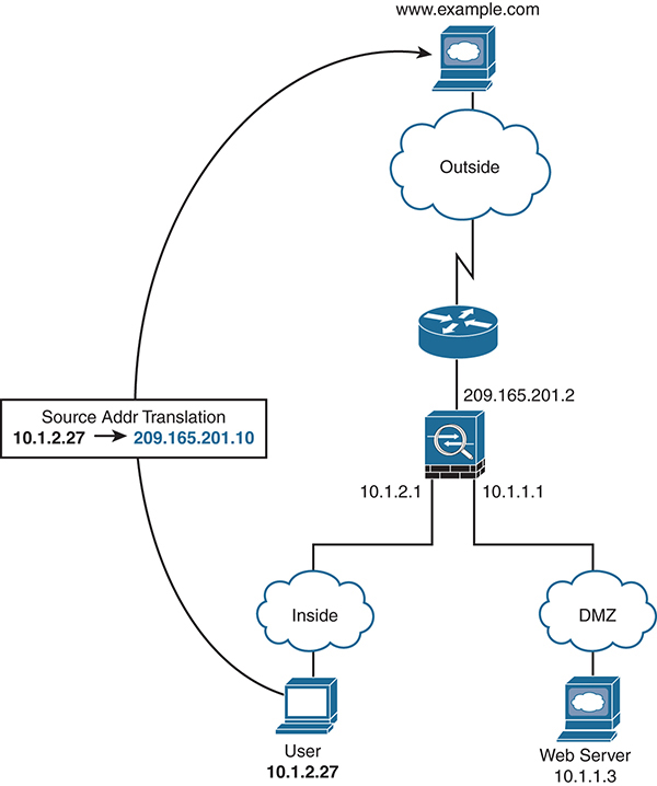
Figure 4-2 Routed Mode ASA
Transparent Mode
Transparent mode (also known as Layer 2 mode) offers a unique to way to insert an ASA at Layer 2, but you need to understand the nuances of this mode of operation. This mode introduces the concept of bridge groups and a Bridge Virtual Interface (BVI). It should be no surprise that routed mode uses Layer 3 addresses and routing, while transparent mode uses Layer 2 addresses to move traffic into and out of the ASA.
A bridge group is a group of two or more interfaces where the ASA bridges traffic. Traffic moving from one interface to another is controlled using access control lists. Each bridge group has only one BVI, and it must be in the same subnet as the bridge group member interfaces. The BVI address is used for sourcing frames from the bridge group. Traffic in a bridge group is isolated from other bridge groups.
Note Because the BVI requires a valid address in the subnet, it is not possible to use /30 network masks as at least three host addresses are required when the BVI address is added.
An ASA in transparent mode actually bridges between two broadcast domains (VLANs). Unlike devices from other firewall vendors, where both interfaces reside in the same VLAN, an ASA in transparent mode has interfaces in different VLANs. These interfaces, however, are mapped to each other as being part of the same bridge group. Understanding the details of how this works with Layer 2 protocols like ARP is critical to passing the CCIE exam.
Figure 4-3 shows a simple configuration of two bridge groups, 1 and 2. Note that the subnets are the same on the two sides of the ASA.

Figure 4-3 Transparent Mode ASA
The BVI interface allows flexibility for an ASA in transparent mode. For example, it is possible for the ASA to act as a DHCPv4 server and perform NAT in this mode of operation.
In addition, consider the following:
![]() As in routed mode, an access rule is not required for traffic sourced from a lower security level and passing to a higher security level. This traffic is allowed by default.
As in routed mode, an access rule is not required for traffic sourced from a lower security level and passing to a higher security level. This traffic is allowed by default.
![]() ARP traffic is allowed through the bridge group in both directions without an access rule. ARP traffic can be controlled by ARP inspection.
ARP traffic is allowed through the bridge group in both directions without an access rule. ARP traffic can be controlled by ARP inspection.
![]() IPv6 neighbor discovery and router solicitation packets can be passed using access rules.
IPv6 neighbor discovery and router solicitation packets can be passed using access rules.
![]() Broadcast and multicast traffic can be passed using access rules.
Broadcast and multicast traffic can be passed using access rules.
![]() Using EtherType rules, AppleTalk, IPX, BPDUs, and MPLS can be allowed.
Using EtherType rules, AppleTalk, IPX, BPDUs, and MPLS can be allowed.
![]() Dynamic routing protocols and VPN traffic can be passed through the ASA in Layer 2 mode.
Dynamic routing protocols and VPN traffic can be passed through the ASA in Layer 2 mode.
This last item is important to note as the ASA does not actually participate in the VPN traffic or routing protocol. Instead, it allows the traffic to pass between two other entities. For example, it is a common deployment in the data center to place a transparent mode ASA between two routers. The routers are peered to each other, but the ASA is still providing stateful inspection and access control of traffic.
BPDUs are passed by default to prevent spanning-tree loops. However, when using failover, it may be beneficial to block BPDUs via an EtherType rule in order to minimize switch ports from going into a blocking state. More details on that can be found later in this chapter, in the section “ASA High Availability Options.”
Unsupported features in transparent mode include DHCP relay and remote access VPN termination.
Transparent Mode Configuration
Configuring an ASA in transparent mode is simple, as shown here:
asa(config)# firewall transparent
Keep in mind that when you do this, the ASA erases its running configuration, so it is important to either have a backup configuration or make this the first command in the initial configuration.
ASA Multiple-Context Mode
Years ago, service providers began offering managed services for their customers. They commonly deployed network devices and then had multiple customers connect to those devices as this saved them money and critical rack space. In this model, each customer did not require new gear.
ASA multiple context (also known as multi-context) mode allows an ASA to be virtually split into multiple logical firewalls, each having a unique access control policy and networking addressing, with individualized management. Enterprise customers benefit from this mode as it allows multiple smaller firewalls to be collapsed into one larger physical ASA. Think of a company with different divisions or a university with different departments; both of these situations provide opportunities for deploying a virtualized ASA, with each department or unit managing only its own virtual firewall.
ASA multiple context mode allows a myriad of ASA deployment options, especially when considering that some contexts could be routed and some could be transparent for the ultimate in flexibility (as discussed later in this chapter).
Note Given that it’s already a virtual appliance, the virtual ASA unfortunately doesn’t support multi-context mode. An ASAv could be deployed similarly to a multi-context ASA except that it uses multiple virtual firewalls in the cloud or on a hypervisor to achieve what the physical ASA does in the chassis.
Multiple Context Configuration Basics
A multi-context mode ASA allows for creative deployment options, and understanding how it works will help a CCIE candidate.
First, let’s cover the basics. Cisco calls each virtualized ASA a “context.” Contexts are licensed features that show up in the standard show version ASA command under “Security Contexts”.
There are two required contexts: the system context and the admin context. The system context is where basic settings such as context names, configuration file URL, and context-to-interface mappings are found. The admin context is like any other context with one exception: It provides root access to all contexts on the physical ASA host.
Physical interfaces are assigned to contexts via the allocate-interface command. It is common to use trunks with sub-interfaces in order to logically carve out more network interfaces as the number of contexts grows.
Using the show context command is a quick way to see contexts and what interfaces are mapped to each, as shown in Example 4-3.
Example 4-3 Multi-Context Mode ASA
asa# show context

Context Name      Interfaces                    URL
*admin            GigabitEthernet0/1.100        disk0:/admin.cfg
                  GigabitEthernet0/1.101
sales             GigabitEthernet0/1.200        disk0:/sales.cfg
                  GigabitEthernet0/1.201
marketing         GigabitEthernet0/1.300        disk0:/marketing.cfg
                  GigabitEthernet0/1.301
Total active Security Contexts: 3
Despite the number of contexts, each ASA contains a finite amount of CPU, memory, and other resources. Without any governance, it is possible for one context to consume most of the resources of a physical ASA. Therefore, Cisco provides features that can limit the amount of resources a context can consume. While memory and CPU cannot be limited, it is possible to limit resources that consume memory and CPU in order to protect other contexts from resource starvation. For example, you can limit the number of active connections, application inspections per second, routing table entries, and similar resources for each context by creating a resource class and specifying which resources are being managed.
Each context uses the resource limits set by the class. To use the settings of a class, assign the context to the class when you define the context. All contexts belong to a default class if they are not assigned to another class. A resource class can be assigned to only one context, which allows the ASA to set the maximum limit. Note that this does not “reserve” the resources for a context but is set as a maximum limit that will not be exceeded.
All contexts are assigned to the default class if they are not explicitly defined to a resource class. For most resources, the default class provides unlimited access to resources for all contexts, except for the following limits:
![]() Telnet sessions: 5 sessions
Telnet sessions: 5 sessions
![]() SSH sessions: 5 sessions
SSH sessions: 5 sessions
![]() IPsec sessions: 5 sessions
IPsec sessions: 5 sessions
![]() MAC addresses: 65,535 entries
MAC addresses: 65,535 entries
At the command line, changing from one context to another requires the changeto context command. The prompt changes accordingly, as shown below:
asa# changeto context sales
asa/sales#
Tip Use a command alias to make this easier.
Occasionally, it may become necessary to reload a context. Unlike the Cisco Nexus switches, the ASA doesn’t support this functionality outwardly. However, it is possible to effectively reload a context by clearing the running configuration and then importing the startup configuration. It is also possible to have a multi-context mode ASA in which some modes are routed and some are transparent. This mixed mode allows for even greater deployment flexibility in a multi-context ASA design. However, not all features in single-context mode are available in mixed multi-context mode.
Understanding the ASA Classifier
When traffic enters a multi-context mode ASA, it must be “classified” in order to determine to which context to send the packet. If each physical interface maps to a context (that is, there are no “shared” interfaces), this usually does not present an issue as the ASA simply sends the packets to the allocated interface(s) for that context. For example, transparent firewall mode requires unique interfaces; they cannot be shared in this mode.
The situation becomes more challenging when interfaces are shared between contexts as the ASA then uses the MAC address to determine where to send the packets. In this case, it is important that each MAC address be unique on each logical interface. This can easily be overridden with manual configuration of unique MAC addresses, but understanding how this works is critical for a CCIE candidate.
If unique MAC addresses are not configured, the classifier performs a destination IP address lookup. For this to work properly, the ASA must have knowledge of the subnets located behind each context, and the ASA relies on the NAT configuration to determine this information. Because each NAT deployment is unique in scope, this can lead to issues if not thought out in advance; therefore, the best practice recommendation is to use unique MAC addresses, which is why this has been the default mechanism since the 8.5 release. Unique MAC addresses are generated using the last 2 bytes of the interface, which can be changed to a custom prefix, if needed.
ASA High Availability Options
Since the earliest days, firewalls have offered various techniques to provide high availability. The oldest and most common is the Active/Standby (A/S) model, where, as the name implies, one firewall unit is active and the other is passive, or standing by. A newer method is the Active/Active (A/A) model, which seeks to improve on weaknesses of the older A/S model. And finally, there is the concept of ASA clustering, which is an N+1 model and achieves both HA and throughput aggregation. Let’s explore each in more detail.
ASA Active/Standby Failover
ASA failover is built on the A/S model. It has been the most commonly deployed high-availability option since the release of the platform in 2005. The primary ASA does all the work, and the standby unit basically waits to come into service only if there is an issue with the primary unit. It also supports a stateful failover mechanism such that state-based traffic flows are minimally impacted during a failover event.
For this mode, several requirements must be met:
![]() The hardware footprint of the two units (RAM, physical interfaces, and model) must match.
The hardware footprint of the two units (RAM, physical interfaces, and model) must match.
![]() Both units must be in the same firewall mode (routed or transparent).
Both units must be in the same firewall mode (routed or transparent).
![]() Both units must be in the same context mode (single or multi-context).
Both units must be in the same context mode (single or multi-context).
![]() Because failover is a licensed feature, each ASA must have proper licensing.
Because failover is a licensed feature, each ASA must have proper licensing.
![]() The two units must be connected via a physical interface known as the failover link.
The two units must be connected via a physical interface known as the failover link.
![]() Optionally, a stateful failover link can be connected if stateful failover is required.
Optionally, a stateful failover link can be connected if stateful failover is required.
Both units could optionally share the failover and stateful link on the same connection to maximize interface efficiency. It is a best practice to connect the two units directly. It is a supported configuration to connect both units using a switch—but only if it is a different switch than the one connecting to the data interfaces. This minimizes the failure domain if one of the switches has issues.
Note Cisco has very specific recommendations on which scenarios are supported and which are not, with many variations on each. For a much deeper discussion on these scenarios and their specifics, see the ASA Configuration Guide: https://www.cisco.com/c/en/us/td/docs/security/asa/asa97/configuration/general/asa-97-general-config/ha-failover.pdf.
Today the granularity to which the A/S ASA monitors the active unit’s health is significant. Timers can be minimized for a more aggressive failover condition, as can the interface monitoring and health tests. For example, if the ASAs each have six physical interfaces, a failover condition could be that a minimum of two interfaces must fail before a failover is initiated. Details and scenario examples are available in the ASA Configuration Guide for each specific code release of the ASA.
A significant benefit of ASA A/S failover is that the active unit replicates the configuration to the standby unit. In fact, when failover occurs, the standby unit effectively assumes the addressing and configuration of the active unit in order to minimize downtime. With newer versions of ASA code, it is possible to execute commands on just the primary or just the standby unit for statistics and network monitoring tools.
Here’s a short summary of the benefits of ASA A/S failover:
![]() It is the most commonly deployed method for ASA high availability.
It is the most commonly deployed method for ASA high availability.
![]() It allows for configuration synchronization from the active unit to the standby unit.
It allows for configuration synchronization from the active unit to the standby unit.
![]() It allows for stateful failover.
It allows for stateful failover.
![]() It allows granular control over the conditions that could lead to a failover event.
It allows granular control over the conditions that could lead to a failover event.
The biggest downside to the A/S model is that it can be deployed only in pairs, and one unit is essentially doing nothing as long as the active unit is working properly. Having two units doubles the amount of rack space, power, and cooling required for every single firewall deployed. It also doubles the cost of the investment in hardware.
Tip You can change the ASA prompt to reflect active versus standby members in a high-availability pair by using the prompt hostname state priority command.
ASA Active/Standby Failover Configuration
When configuring ASA failover, start with the ASA that you want to be the primary. Remember that the ASA will require at least one network interface dedicated to the standby unit. Optimally the two ASAs will be cabled directly together, but Cisco supports ASA failover under specific conditions. Please reference the ASA Configuration Guide for details on what is supported.
The following is a sample configuration on the ASA primary unit for Active/Standby high availability.
Use the following command to make this ASA the primary unit at startup:
failover lan unit primary
Use the following command to designate a dedicated interface for failover:
failover lan interface failover GigabitEthernet0/4
This is the interface where heartbeats are exchanged between units and, optionally, state information.
Failover traffic by default communicates in plaintext. Using a key allows the traffic to be encrypted:
failover key {key}
Tell the ASA to use this interface for passing state information between units:
failover link failover GigabitEthernet0/4
Assign active and standby addresses to the failover link:
failover interface ip failover 10.10.99.1 255.255.255.252 standby 10.10.99.2
Note that failover is not active until the failover command is applied:
failover
Assuming that the standby unit is using the same failover interface (g0/4), the configuration on that unit is exactly the same except that it is designated as the standby unit in the failover lan unit command.
After waiting for the two units to handshake and sync configuration, you can verify that failover has been configured correctly by using the show failover command, as shown in Example 4-4.
Example 4-4 Verifying ASA Active/Standby Failover Configuration
asa/pri/act# sh failover
Failover On
Failover unit Primary
Failover LAN Interface: failover GigabitEthernet0/4 (up)
Reconnect timeout 0:00:00
Unit Poll frequency 1 seconds, holdtime 15 seconds
Interface Poll frequency 5 seconds, holdtime 25 seconds
Interface Policy 1
Monitored Interfaces 1 of 516 maximum
MAC Address Move Notification Interval not set
failover replication http
Version: Ours 9.4(4)5, Mate 9.4(4)5
Last Failover at: 18:13:58 EST Dec 8 2017
        This host: Primary - Active
                Active time: 5087761 (sec)
                slot 0: asa hw/sw rev (1.0/9.4(4)5) status (Up Sys)
                  Interface outside (192.168.1.5): Normal (Not-Monitored)
                  Interface outside2 (10.1.1.1): Normal (Not-Monitored)
                  Interface dmz (10.1.2.1): Link Down (Not-Monitored)
Other host: Secondary - Standby Ready
                Active time: 0 (sec)
                slot 0: asa hw/sw rev (1.0/9.4(4)5) status (Up Sys)
                  RTP-DMZ Interface outside (192.168.1.6): Normal (Not-Monitored)
                  RTP-DMZ Interface outside2 (10.1.1.2): Normal (Not-Monitored)
                  RTP-DMZ Interface dmz (10.1.2.2): Normal (Not-Monitored)
ASA Active/Active Failover
Active/Active failover was introduced on the ASA to improve upon the legacy A/S model. As the name implies, both units are active, which is an improvement over the A/S model discussed previously.
However, A/A can be deployed only in pairs and requires the use of ASA multiple context mode. In fact, the ASA A/A model still uses A/S, but with ASA virtualization, it provides for two logical A/S failover pairs in two physical ASAs. Given that multiple context mode, like A/S failover, is a licensed feature, care must be taken to ensure proper feature licensing to make this work.
From a feature standpoint, A/A failover is nearly the same as A/S failover. Remember that calling it A/A is really a bit of marketing because it really is two A/S pairs running in multi-context mode. Figure 4-4 shows an example of A/A failover.
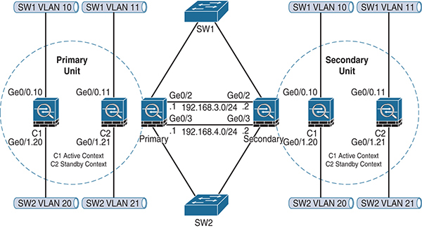
Figure 4-4 ASA Active/Active Failover
There is one more shortcoming that a good CCIE candidate has likely noticed: A/A mode does not really increase the amount of available ASA throughput. It is a common mistake to think that two ASAs would allow for double the amount of data plane throughput. They do provide double the throughput until one of the ASA failover units fails, and then the available throughput is cut in half. Here’s the problem: If the network throughput minimum requirements were based on the double number, then half the packets will be dropped during a physical ASA failover!
Note An ASA in Active/Active failover can only fail over as a hardware unit. Individual contexts cannot fail over separately.
ASA Active/Active Failover Configuration
A/A failover requires multiple context mode to be enabled. The security contexts are then divided into failover groups. A failover group is a logical group of one or more contexts with a maximum of two groups allowed. The admin context is always a member of failover group 1. Unassigned contexts by default appear in this group as well. From this point, the configuration is nearly identical to the configuration of Active/Standby with some differences.
Active/Active failover generates virtual MAC addresses for the interfaces in each failover group. Best practice is to manually assign these addresses because different ASAs can auto-generate duplicate virtual addresses and cause connectivity problems.
The same configuration shown earlier, in the section “ASA Active/Standby Failover,” is used again in Example 4-5 for clarity.
Example 4-5 ASA Stateful Failover Configuration
failover lan unit primary
failover lan interface failover GigabitEthernet0/4
failover key {key}
failover link failover GigabitEthernet0/4
failover interface ip failover 10.10.99.1 255.255.255.252 standby 10.10.99.2
And now you create the failover groups, placing the admin context in failover group 1, as shown in Example 4-6.
Example 4-6 ASA Failover Group Configuration
failover group 1
  primary
  preempt
failover group 2
  secondary
  preempt
context admin
  join-failover-group 1
Handling Asymmetric Traffic
In some cases, ASAs configured for A/A failover may receive asymmetric traffic. The A/S model avoids this completely because only one path is active at any given time (the standby never passes traffic). By default, asymmetric traffic is dropped by the stateful inspection engine on the firewall. To mitigate this, the ASA supports sending the asymmetric traffic back to the source ASA. The ASA allows for interfaces to be defined as part of an ASR group. The asr-group command is placed under the interface configuration as shown in Example 4-7. Note that it is defined only on interfaces where asymmetric traffic might appear. Figure 4-5 shows how asr-groups forward asymmetric traffic on the Active/Active ASA pair.

Figure 4-5 Asymmetric Flow on an Active/Active ASA Pair
Example 4-7 Configuring an ASR Group
Context ISP-1
interface GigabitEthernet0/0
  nameif outsideISP-A
  security-level 0
  ip address 192.168.1.1 255.255.255.0 standby 192.168.1.2
  asr-group 1
Context ISP-2
interface GigabitEthernet0/0
  nameif outsideISP-B
  security-level 0
  ip address 192.168.2.1 255.255.255.0 standby 192.168.2.2
  asr-group 1
ASA Clustering
ASA clustering is a feature that allows for multiple ASA physical firewalls to be combined together in order to provide a scalable way to increase available firewall throughput. Historically customers were forced to buy bigger and more powerful firewalls as their throughput requirements increased. ASA clustering allows for more firewalls to be added over time, which provides investment protection.
ASA clustering also provides a new mechanism for high availability. This is an improvement over the A/S and A/A pair limitation as clustering supports up to 16 members providing N+1 redundancy. However, not every ASA feature is supported when clustering is enabled, so design requirements must be carefully considered. ASA clustering is a licensed feature that must be enabled before configuration.
Similar to A/S and A/A, clustering automatically replicates the configuration across cluster members. In addition, much as with the failover and stateful failover link required in A/S and A/A, clustering requires the configuration of a cluster control link (CCL). This link acts as both a control plane and a data plane for cluster operations. Member unit health checks and state table replication both happen across the CCL. Given its role in cluster operations, the CCL must be protected with redundancy mechanisms because losing the CCL causes an immediate evacuation of the member unit from the cluster.
Note Cisco recommends that the CCL sizing be equal to the maximum aggregate throughput of the combined data plane. For example, if an ASA has two 10 GB interfaces in a port channel, it is recommended that the CCL also be sized as two 10 GB interfaces via a port channel.
Best practice is to use Link Aggregation Control Protocol (LACP) to dynamically configure port channels for the CCL, with each link connecting to a different switch. This extends the potential failure domains across the two switches and avoids dependency on a single interface link failure. This configuration is shown in Figure 4-6. Each ASA cluster member has one “leg” to each switch, and each one is placed in a port channel. The port channel provides bandwidth aggregation, link redundancy, and load-balancing capabilities by default. The recommended best practice is to also use port channels for the CCL as it must match the aggregate data plane bandwidth. In addition to link bandwidth aggregation, the port channel provides fault tolerance, which is critical due to the role of the CCL.
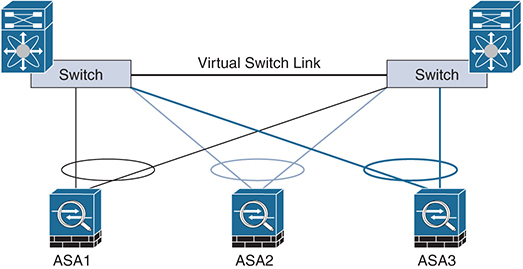
Figure 4-6 ASA Clustering Operation
Clustering Performance
Due to the overhead required by the ASA clustering control plane, a cluster will likely not achieve the maximum combined throughput of the individual ASA units. Many factors affect the actual overhead, including size of cluster, asymmetric flow reassembly and health of individual units. For design purposes, Cisco has created benchmarks that allow a reasonable ASA cluster throughput calculation:
![]() 70% of the combined throughput
70% of the combined throughput
![]() 60% of the maximum connections
60% of the maximum connections
![]() 50% of connections per second
50% of connections per second
For example, an ASA 5585-X with SSP-40 can pass approximately 10 Gbps of stateful firewall traffic (multiprotocol) by itself. A cluster of eight units would yield a total available throughput of approximately 56 Gbps (8 × 10 × .70).
Requirements for ASA Clustering
Clustering has a very specific set of prerequisite requirements:
![]() All units in a cluster must be the same hardware model with the same DRAM. Flash memory can vary.
All units in a cluster must be the same hardware model with the same DRAM. Flash memory can vary.
![]() All units in a cluster must be on the same major software release. Hitless upgrade is supported across minor releases.
All units in a cluster must be on the same major software release. Hitless upgrade is supported across minor releases.
![]() All units in a cluster must be in the same firewall mode (routed or transparent).
All units in a cluster must be in the same firewall mode (routed or transparent).
![]() All units in a cluster share the same cluster ID, encryption, and 10 Gbps I/O license information (5585-x only).
All units in a cluster share the same cluster ID, encryption, and 10 Gbps I/O license information (5585-x only).
Clustering requires the use of custom extensions to the LACP that Cisco created in the switches as cLACP. This allows the ASA firewalls in the cluster to be treated as one logical firewall by the switching fabric, allowing them to negotiate port channels for the data plane. This in turn allows for scalability and redundancy in the data center fabric as clustering is not intended for use at the network edge.
Operational Modes
Understanding how an ASA cluster processes connections is critical for deployment. To begin, there are three possible roles for each cluster member: owner, director, or forwarder. These roles are for every connection traversing the firewall. It is not uncommon in a data center with significant traffic load for every cluster member to be in all three roles simultaneously. Let’s examine the differences:
![]() Owner: The owner role is the first unit to receive the connection request. There is only one owner per connection, and the owner maintains the state of the connection.
Owner: The owner role is the first unit to receive the connection request. There is only one owner per connection, and the owner maintains the state of the connection.
![]() Director: The director processes lookup requests from forwarders and acts as a backup in case the owner fails. Every connection has an owner and a director. The director is derived from a hash from the source and destination IP address and TCP ports.
Director: The director processes lookup requests from forwarders and acts as a backup in case the owner fails. Every connection has an owner and a director. The director is derived from a hash from the source and destination IP address and TCP ports.
![]() Forwarder: In the case of asymmetric traffic flows, the forwarder forwards packets to the owner. A forwarder queries a director to find the owner, and this traffic is back-hauled across the CCL. For network forwarding efficiency, it is critical that asymmetry be avoided if possible because these flows eat up valuable bandwidth in the CCL.
Forwarder: In the case of asymmetric traffic flows, the forwarder forwards packets to the owner. A forwarder queries a director to find the owner, and this traffic is back-hauled across the CCL. For network forwarding efficiency, it is critical that asymmetry be avoided if possible because these flows eat up valuable bandwidth in the CCL.
Figure 4-7 shows a typical new connection forming in an ASA cluster.
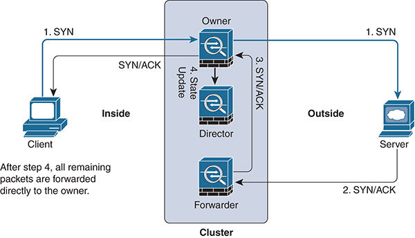
Figure 4-7 ASA Cluster Control Plane Operation with Asymmetric Traffic
ASA Clustering Data Plane
As noted earlier, scalable firewall throughput is a main reason for enabling the ASA clustering feature. Because the ASA cluster acts as one logical firewall entity, how it connects to the switch fabric is vital.
The best practice for configuring the data plane interfaces in an ASA cluster is to use the Spanned EtherChannel method. This provides the benefit of link aggregation and link redundancy for all the link interfaces in the port channel. The switches terminating the port channel allow for different means to load-balance traffic through the ASA cluster. The recommended practice is to use either source-dest-ip or source-dest-ip-port load-balancing algorithms in order to minimize the potential for asymmetric flows. Asymmetric flows degrades the overall capacity of the cluster as each flow has to be forwarded across the CCL.
Figure 4-8 shows a typical Spanned EtherChannel configuration.

Figure 4-8 ASA Cluster of Spanned Port Channels
Note As noted earlier, some ASA features are not supported with clustering. In addition, some features may work in a distributed fashion on each cluster member, while others work only centrally on a single cluster member at a time. See the ASA Configuration Guide for your software release for more details.
ASA Clustering Data Plane Configuration
If the hardware and software requirements are met, an ASA clustering configuration requires only a few commands. Because most ASA cluster deployments use the spanned port-channel method, make sure the port channels are up and that LACP is configured properly.
To begin, you need to tell each ASA in the cluster that you are using Spanned EtherChannel mode. This is by far the most common deployment as it takes advantage of the integrated load sharing in port channels combined with link aggregation and redundancy. This is performed as a global command and may require a reboot, so it should be configured first, in global configuration mode, as shown in Example 4-8.
Example 4-8 ASA Spanned Port-Channel Configuration
cluster interface-mode spanned
Cluster interface-mode has been changed to 'spanned' mode successfully. Please complete interface and routing configuration before enabling clustering.
In Example 4-9, g0/0 and g0/1 are configured in port-channel 1, and g0/2 and g0/3 are configured for port-channel 2. Port-channel 1 will act as the ASA inside interface, and port-channel 2 will act as the outside interface. The active mode designates that these interfaces will actively use LACP to establish the port channel. Active mode LACP is recommended for ASA port channels.
Example 4-9 ASA Port-Channel Configuration
interface GigabitEthernet0/0
 channel-group 1 mode active vss-id 1
!
interface GigabitEthernet0/1
 channel-group 1 mode active vss-id 1
!
interface GigabitEthernet0/2
 channel-group 2 mode active vss-id 2
!
interface GigabitEthernet0/3
 channel-group 2 mode active vss-id 2
When your port channels are up and valid, it’s time to layer in the ASA clustering configuration. You need to make sure that your load-balancing method is set correctly. As noted in the previous section, Spanned EtherChannel mode is the most common configuration option. Both port channels in Example 4-10 are spanned.
Example 4-10 ASA Spanned Port-Channel Configuration
interface Port-channel1
 lacp max-bundle 8
 port-channel span-cluster vss-load-balance
!
interface Port-channel2
 lacp max-bundle 8
 port-channel span-cluster vss-load-balance
Now that your data plane interfaces are up and port-channeled, you can insert the clustering commands. First, you need to name the cluster. Any name works, as long as it matches on all cluster members. Here’s an example:
cluster group CCIE
Next, you need to give the local cluster member a unique name so it can be easily identified in the cluster and for troubleshooting:
local-unit 5525-1
Next, you have to define the cluster control interface (also called the cluster control link [CCL]). This is the interface, discussed previously, that is used for intra-cluster communication, asymmetric traffic forwarding, and other miscellaneous control plane functions for the cluster. Best practice is to use another port channel, but this is not required. In the lab for this book, we are using port-channel 3 as the cluster control interface. The address needs to be unique as all cluster members will communicate using this address. Here is an example:
cluster-interface Port-channel3 ip 99.99.99.1 255.255.255.0
Finally, you have to give this cluster member a priority to break ties during the election process. Lower numbers are higher priority. Here is an example:
priority 10
And when everything else looks good, you enable clustering:
enable
ASA Clustering Troubleshooting
Most of the issues around ASA clustering fall into two areas: physical interface configuration and the cluster control plane. Ensure that physical interfaces are cabled properly and that port channels, when used, are up. Clustering relies on a stable data plane in order to manage traffic flow, load-balancing, and intra-cluster communication. In addition to information learned with the basic show interface command, the output from show port-channel brief is helpful for a quick sanity check.
The cluster control plane is used by all cluster members to communicate everything from cluster health, to reachability, to flow ownership. Therefore, making sure the cluster connection is up and that all units are able to communicate with each other over the network is important. There are many reasons cluster members may be unable to join the cluster. Example 4-11 shows the output of the show cluster info command from a properly working ASA cluster with two members, 5525-1 and 5525-2.
Example 4-11 Verifying ASA Cluster Health
ASA5525-1/master# show cluster info
Cluster CCIE: On
    Interface mode: spanned
    This is "5525-1" in state MASTER
        ID        : 0
        Version   : 9.4(4.5)
        Serial No.: FEH199XXXX
        CCL IP    : 99.99.99.1
        CCL MAC   : c067.af03.2dee
        Last join : 09:20:04 EST Dec 11 2017
        Last leave: 09:14:16 EST Dec 11 2017
Other members in the cluster:
Unit "5525-2" in state SLAVE
        ID        : 1
        Version   : 9.4(4.5)
        Serial No.: FDH199XXXX
        CCL IP    : 99.99.99.2
        CCL MAC   : c067.af03.2cee
        Last join : 09:21:04 EST Dec 11 2017
        Last leave: 09:15:16 EST Dec 11 2017
Other useful show commands are as follows:
    show cluster info [health]
    show asp cluster counter
    show conn
ASA clustering has a fairly robust set of debugging commands. On a production network, you should use these commands with discretion. Some of the most useful commands are debug cluster ccp for troubleshooting the cluster control plane and debug cluster datapath for troubleshooting data plane issues.
Enabling Routing Protocol Support on the ASA
At a basic networking level, an ASA in routed mode acts like a router. It contains a routing table and supports dynamic routing protocols and may be used as a gateway in deployment. The ASA has evolved to be more router-friendly, but it has not always been this way. Customers today require that a firewall be both a security device and a networking device, and this section examines some of those features.
The most important criterion for moving traffic through an ASA is determining the egress interface followed by the next-hop selection. NAT changes this behavior on the ASA somewhat (and is examined in more detail in the next section).
The ASA supports equal-cost multipath (ECMP) routing with up to eight equal-cost static or dynamic routes per interface. The hashing algorithm uses the source and destination IP address to determine which interface to use. The ASA also supports policy-based routing (PBR), which allows an override of the routing table based on specific criteria. PBR is used when certain defined conditions are met, causing the ASA to forward traffic to a specific destination. Like IOS, PBR on the ASA is configured via route maps and is a powerful tool in scenarios where the general routing table is not sufficient.
More recently, the ASA has added support for Bidirectional Forwarding Detection (BFD). This feature is used as a failure detection method that allows fast failover for routing protocols. It originated in the data center, where downtime can be costly, and it works on the principle that peers exchange control information that advertises their reachability. It vastly improves the timers and heartbeat mechanisms built into the routing protocols and is considered a complementary feature.
As of the 9.6 release, the ASA supports the following routing protocols as well as static and multicast routing:
![]() BGP
BGP
![]() OSPF
OSPF
![]() IS-IS
IS-IS
![]() EIGRP
EIGRP
These protocols have been around for many years, and their usage is well known in the networking industry; this book therefore does not discuss them in detail. Their configuration on the ASA, in many cases, is very similar to configuration in IOS. It is important to consider the application of the routing protocol and how it integrates into the networking fabric. As mentioned earlier, the ASA today is both a security device and a network device and should be treated accordingly. It should be noted that all these routing protocols are supported only in ASA routed mode.
BGP is the standard for both Internet routing and enterprise networks. It is very powerful in that it has the ability to carry metadata (tags) in the routing updates. BGP Multipath makes it attractive for networks where equal-cost prefixes point to the same destination prefix. The ASA version, while not as robust as its Cisco router counterpart, still provides a strong capability to standardize on a single routing protocol for both enterprise and service providers. It supports both IPv4 and IPv6, making it well suited for dual-stack environments.
OSPF has become a dominant IGP in the past 15 years due to its multivendor interoperability. OSPF and BGP both support the Nonstop Forwarding (NSF) feature, which allows the data path to still function even while routing protocol peering information is being restored. The ASA is flexible in that it supports most of the necessary OSPF features, including supporting two process IDs running concurrently. The ASA supports OSPFv1, OSPFv2, and OSPFv3. Notably, OSPFv2 does not support IPv6, but OSPFv3 does.
IS-IS has been most popular in the service provider world but has seen a recent resurgence in enterprise networks. Like most other link-state routing protocols, it requires some planning to come up with the best network design.
EIGRP is arguably the easiest routing protocol on this list to get up and running as it requires very little planning and handles the neighboring process automatically. Its popularity stems from its deployment simplicity. Unfortunately, it does not support IPv6, which may limit its popularity for dual-stack networks.
Firewalls have traditionally faced challenges with multicast traffic. It is common in a network with large amounts of multicast traffic to deploy the ASA in transparent mode to minimize disruption because the ASA in this mode does not actively route the multicast packets. However, for the adventurous, the ASA supports stub multicast routing and PIM multicast routing—but only one at a time. Multicast routing is supported only in single-context mode, and if the ASAs are clustered, only the primary unit participates in the multicast routing process.
ASA Routing Protocol Configuration
Configuration of ASA routing protocols is very similar to configuration in IOS devices. It involves defining the routing protocol and process and any networks to be advertised, followed by any options. Example 4-12 shows a sample EIGRP configuration on an ASA followed by a listing of its neighbors:
Example 4-12 ASA EIGRP Configuration
router eigrp 150
 network 10.1.1.0 255.255.255.0
 network 10.254.254.0 255.255.255.255
 passive-interface default
 no passive-interface inside

asa(config)# show eigrp neighbors
EIGRP-IPv4 Neighbors for AS(150)
H   Address                 Interface       Hold Uptime   SRTT   RTO   Q  Seq
                                            (sec)         (ms)        Cnt Num
2   10.9.0.2                inside           13     3d19h 1      200  0   275156

1   10.9.0.13               inside           13     3d19h 1      200  0   54719

0   10.9.0.1                inside           11     3d19h 5      200  0   19741
ASA Routing Protocol Troubleshooting
ASA routing protocol configuration troubleshooting is identical to IOS troubleshooting. Ensuring that adjacencies are formed and links are properly configured are good starting points. In most cases, the ASA routing protocol commands are not as advanced as on IOS devices.
Debugging EIGRP is limited to a few commands, as shown in Example 4-13. debug eigrp neighbors is useful for troubleshooting the neighbor EIGRP peering process, and debug eigrp packets shows adjacency information and advertisement update–related information.
Example 4-13 Debugging EIGRP
asa(config)# debug eigrp ?
exec mode commands/options:
  fsm        EIGRP Dual Finite State Machine events/actions
  neighbors  EIGRP neighbors
  packets    EIGRP packets
  transmit   EIGRP transmission events
ASA Clustering Best Practices
Checking the health of a cluster involves understanding what is happening at a cluster level as well as for each individual cluster member. Because the cluster member slaves replicate their configuration from the master, it can be confusing to troubleshoot and maintain individual ASAs. As mentioned earlier in this chapter, best practice is to change the prompt to make it easy to know the name and state of the member to which the console is attached, as follows:
prompt cluster-unit state
Optionally, if this is a multi-context cluster, add the context keyword:
prompt cluster-unit context state
During the CCIE lab exam, time must be used as efficiently as possible. Using command aliases on the ASA helps you save time and keystrokes. ASA clustering allows for commands to be sent to all cluster members simultaneously via the cluster exec command. This is useful when you’re saving a configuration or doing other similar tasks that need to be sent to the cluster as a whole. For example, you can use ce in order to reference the command cluster exec, which saves keystrokes:
command-alias exec ce cluster exec
It is best practice during the lab exam to set other common commands using command-alias in the same fashion.
Traffic with the ASA
All modern firewalls, including the ASA, provide some level of address translation capability. The ASA’s features have evolved over time to become more IOS-like in their command structure as the use cases for translation continue to grow.
Network Address Translation (NAT)
In the early days of the Internet there was no need for NAT as there were more IPv4 addresses than there were hosts. But as the Internet grew, so did the need to come up with methods to conserve the address space to accommodate the growth. Like most other features, ASA NAT evolved to be more granular in order to fit more extreme use cases. Today NAT is more than just a security mechanism. It has become a common tool for fixing overlapping address spaces and connecting dissimilar networks together. NAT is supported in both routed and transparent mode on the ASA, which makes it nearly universal in its application. This section examines different types of NAT and the ways it is configured.
ASA 8.3+ NAT Configuration Changes
Note that the ASA NAT configuration changed significantly in the 8.3 release. Cisco reworked the ASA to make NAT easier to configure and troubleshoot. Candidates familiar with older versions of the ASA need to understand the differences between older and newer versions as they are significant. The biggest change is that IP addresses referenced in ACL configuration (in 8.3 and newer) now use the real IP address, whereas older versions of code referenced the global (translated) IP address. Cisco has detailed documentation on its website highlighting more differences between the old and new configuration methods: https://www.cisco.com/c/en/us/td/docs/security/asa/asa83/upgrading/migrating.html
A CCIE candidate needs to have a strong understanding of the various ways NAT is configured on the ASA. In concept NAT is fairly simple; after all, you are exposed to it every day as you surf the Internet. However, ASA NAT configuration has some nuances that can only be absorbed by thoroughly exploring the vast configuration options offered. This section introduces NAT using the Cisco nomenclature.
NAT Terminology
Cisco uses specific terminology to explain NAT configuration:
![]() A real address is an address prior to translation. Typically this is the inside, or private side, network.
A real address is an address prior to translation. Typically this is the inside, or private side, network.
![]() A mapped address is an address that a real address is translated to. Typically this would be the outside or untrusted network.
A mapped address is an address that a real address is translated to. Typically this would be the outside or untrusted network.
![]() Bidirectional initiation indicates that NAT applies to both directions: traffic to the host and from the host.
Bidirectional initiation indicates that NAT applies to both directions: traffic to the host and from the host.
![]() Source and destination NAT compares both source and destination to NAT rules. One or both can be translated or not.
Source and destination NAT compares both source and destination to NAT rules. One or both can be translated or not.
Types of NAT
Cisco has defined specific applications of NAT:
![]() Dynamic NAT: Real addresses are translated to mapped addresses (many-to-many), which is commonly used for Internet access, as an example.
Dynamic NAT: Real addresses are translated to mapped addresses (many-to-many), which is commonly used for Internet access, as an example.
![]() Dynamic Port Address Translation (PAT): Real addresses are translated to a single mapped address (many-to-one). Often in the egress interface address, ports are used to differentiate between real hosts.
Dynamic Port Address Translation (PAT): Real addresses are translated to a single mapped address (many-to-one). Often in the egress interface address, ports are used to differentiate between real hosts.
![]() Static NAT: This is a static (one-to-one) mapping between a real address and a mapped address. This mapping will always translate bidirectionally and is common for mail servers, web servers, and so on.
Static NAT: This is a static (one-to-one) mapping between a real address and a mapped address. This mapping will always translate bidirectionally and is common for mail servers, web servers, and so on.
![]() Identity NAT: This is a unique application of NAT in which a real address is translated to itself. This is a common way to exempt certain hosts from NAT translation.
Identity NAT: This is a unique application of NAT in which a real address is translated to itself. This is a common way to exempt certain hosts from NAT translation.
Applying NAT
Like many other features on the ASA, NAT has evolved to meet the needs of a variety of uses and deployment scenarios. The vast majority of NAT configurations are covered by network object NAT. This is the easiest way to configure NAT on the ASA because it is defined at the same time as the network object. A network object can be a single IP host, a range, or a whole subnet. These objects can then be referenced in network groups to simplify policy creation on the ASA. Because NAT is configured at the object level, it offers easy differentiation between hosts that require NAT and those that don’t.
NAT and IPv6
The ASA has a long history of robust features with IPv6. Accordingly, NAT features have evolved to incorporate IPv6. The ASA can translate between IPv4 and IPv6 (NAT46), IPv6 and IPv4 (NAT64), and IPv6 and IPv6 (NAT66) at the same time. The recommended best practice for NAT46 and NAT66 is to use static NAT due to the large amount of available IPv6 address space. Dynamic PAT is recommended for NAT64 because the IPv4 mapped address space is often more constrained.
Dynamic NAT
Dynamic NAT is the most common and easiest NAT configuration on the ASA. It translates real addresses to mapped addresses where the mapped address pool is typically smaller than the real address pool. Addresses are translated on a first-come, first-served basis from the mapped pool. A NAT translation exists only for the duration of the connection, and there is no guarantee that a given host will receive the same mapped address. Dynamic NAT usage is very common for allowing hosts to communicate on the Internet.
Figure 4-9 illustrates basic dynamic NAT.
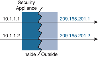
Figure 4-9 Dynamic NAT
Dynamic NAT has some limitations. Most obvious is that the mapped pool can run out of addresses if there are more real hosts than mapped addresses. New real host connections would not be allowed. Dynamic PAT, covered in the next section, is often used in conjunction to assist where hosts may overload a dynamic pool.
Another downside to dynamic NAT is that it may consume a larger number of mapped addresses. Some networks may not have the address space to dedicate for this function.
Dynamic PAT
Dynamic PAT is similar to dynamic NAT except that only a single mapped address is used for translation. This allows multiple real hosts to communicate with translation while minimizing the number of mapped addresses that are in use. It also serves as a method to protect the network from exhausting mapped address space when used in conjunction with dynamic NAT.
Real hosts are tracked via port numbers. If possible, the actual source port number is used; otherwise, a unique port number is assigned to a connection (see Figure 4-10).
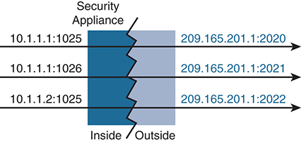
Figure 4-10 Dynamic PAT (NAT Overload)
Like dynamic NAT, dynamic PAT has some drawbacks:
![]() Some multimedia applications and protocols don’t work with PAT if their control plane is different than the data plane.
Some multimedia applications and protocols don’t work with PAT if their control plane is different than the data plane.
![]() When dynamic PAT is used, network traffic analytics show a large amount of traffic from a single address. This might affect thresholds for network packet dispersion.
When dynamic PAT is used, network traffic analytics show a large amount of traffic from a single address. This might affect thresholds for network packet dispersion.
Static NAT
Static NAT is used when continuous bidirectional address mapping is required for a host. Unlike dynamic NAT, which pools mapped addresses, static NAT creates a one-to-one relationship for the host. Static NAT is commonly used when specific hosts need to be reachable from outside the network.
Static NAT operation is outlined in Figure 4-11. Note the directions of the arrows.

Figure 4-11 Static NAT
Static NAT can also statically map ports as well as addresses. This provides more flexibility when a variety of network services are offered (see Figure 4-12).

Figure 4-12 Static NAT with Port Mapping
It is also possible to use static NAT for a one-to-many mapping where a single real address maps to multiple mapped addresses. This is common in deployments where a load balancer is managing connectivity to a server farm. The load balancer is the single real IP address that is known by multiple mapped addresses. In this case, only the first mapped address is used for outbound traffic, but the additional mapped addresses are used for inbound traffic (see Figure 4-13).
Identity NAT
Identity NAT is a specialized mapping option in which a host maps an address to itself. It is typically used to exclude a specific host from translation when a large range of hosts are part of a NAT rule. It is also required for remote access VPN when host client traffic needs to be exempt from NAT. Identity NAT is shown in Figure 4-14.

Figure 4-13 Static NAT Mapped to Different Addresses
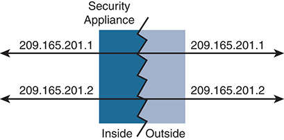
Figure 4-14 Identity NAT
Identity NAT Configuration
Cisco recommends using auto-NAT via network object configuration for most NAT configurations. Manual NAT, such as identity NAT outlined previously, should be used only when necessary. There are differing opinions on which form is easier to configure, but a CCIE candidate should have a good working knowledge of both.
Let’s begin with a simple auto-NAT configuration that is performing dynamic PAT on the outside interface for the internal network. This is similar to the majority of firewall NAT configurations used in the world today. Here are the steps required to configure dynamic PAT on the ASA:
Step 1. Create a network object that defines the local inside network. In this example, it is 10.1.1.0/24, called INSIDE-NET:
object network INSIDE-NET
  subnet 10.1.1.0 255.255.255.0
The best practice of using network objects on the ASA allows for policies that are easier to understand, which is helpful when troubleshooting.
Step 2. Define a NAT policy under the network object:
nat (inside,outside) dynamic interface
This tells the ASA to dynamically translate any traffic from the inside network (defined in the network object) destined for the outside interface. NAT uses the outside interface of the ASA, which conserves the global address space.
An option is to use the any keyword in the NAT statement to allow greater flexibility if the ASA has multiple egress interfaces:
nat (inside,any) dynamic interface
Without it, each egress interface would have to be defined, adding more complexity to the configuration.
Note The ordering of the NAT configuration commands could confuse some candidates as the ASA will take all the commands as ordered here. However, the commands are actually placed in the ASA configuration in different sections. The address configuration is placed within the network objects section, while the NAT configuration is placed in the respective NAT section. Candidates should familiarize themselves with where the commands are entered in the configuration.
Another common deployment option is to build a static NAT translation for a web server on a DMZ for outside (untrusted) access. Much as in the preceding steps, you create the network object and then apply the NAT statement. In this example, the object is a host called WEB-SERVER, and its global address is 10.100.100.15. There is also an interface with a nameif called dmz already defined:
object network WEB-SERVER
  host 10.1.1.15
  nat (dmz,outside) static 10.100.100.15
What if there is a pool of real (global) addresses from which to pull dynamically? In familiar fashion, create the network pool object and then map the dynamic NAT statement:
object network NAT-POOL
  range 10.100.100.100 10.100.100.125
object network INSIDE-NET
  subnet 10.1.1.0 255.255.255.0
  nat (inside,outside) dynamic NAT-POOL
The pool is using a portion of the global address defined as 10.100.100.100 through 10.100.100.125. This example uses the INSIDE-NET object from earlier. The NAT policy is applied under the inside network object group configuration.
Identity NAT is an option when a host gets translated to its originating (real) source address. Using the web host from earlier, this sample configuration translates the server’s address to itself:
object network WEB-SERVER
  host 10.1.1.15
  nat (dmz,outside) static WEB-SERVER no-proxy-arp route-lookup
In some cases, more granular control is required. Twice NAT (also called manual NAT) is an option that identifies the source and destination addresses in a single rule. For example, when accessing ISP A, host A presents one address, and when accessing ISP B, host A is translated into a different address. It is important to remember that in Twice NAT, the rules are bidirectional, so source and destination are temporal. Using the subnet from earlier in this example, this configuration allows web hosts for the specified network to be translated into different addresses based on the traffic destination.
Twice NAT is a more advanced option that allows greater flexibility than network object NAT in that both the source and the destination addresses are identified in a single rule. A typical use case for twice NAT is a scenario where a host communicates with two different company divisions that have different IP subnets. Twice NAT translates the addresses based on the destination address, which network object NAT can’t easily accommodate. Here is a simple configuration for twice NAT:
object network WEB-NET
  subnet 10.1.1.0
  nat (inside,dmz-1) source dynamic WEB-NET interface
  nat (inside,dmz-2) source dynamic WEB-NET interface
Finally, another keyword is used in some scenarios, where ordering of the NAT statements (as in the CCIE lab exam) is critical. The after-auto keyword is used in the manual NAT statements to push the NAT statements below the network object section of the NAT rules. Remember that, by default, manual NAT rules appear at the top of the NAT table. Using after-auto in the NAT statement, as its name implies, pushes that specific NAT configuration to the bottom section of the table as seen here:
  nat (inside,dmz-1) after-auto source dynamic WEB-NET interface
  nat (inside,dmz-2) after-auto source dynamic WEB-NET interface
It’s important to check the order of the NAT statements to verify it is as intended. In certain cases, the ASA does not overwrite the old NAT statement, and it must be deleted manually; otherwise, it will never be checked.
NAT and IPv6
When hosts on IPv4-only networks need to talk to hosts on IPv6-only networks, address translation must occur. NAT46 describes the translation of IPv4 addresses into the IPv6 address space, while NAT64 describes the translation from IPv6 to IPv4. On the other hand, NAT66 translates IPv6 addresses into IPv6 addresses. Fortunately, the ASA can do both IPv4 and IPv6 NAT at the same time. The IPv6 configuration steps are nearly identical to those for IPv4 NAT.
It is common with NAT64 to use dynamic PAT due to the relatively small IPv4 address space compared to IPv6. For the same reasons, it is not recommended that you use dynamic PAT with NAT46; therefore, the ASA supports only static mappings into the IPv6 space.
Let’s look at a configuration example that has two networks: Host A on the inside speaks only IPv4, while Host B on the extranet interface has only an IPv6 address (see Figure 4-15). Configuring dual-stack NAT on the ASA allows them to communicate.

Figure 4-15 NAT and IPv6
You need to configure both NAT46 and NAT64 on the ASA for the two hosts to pass traffic. Follow these steps:
Step 1. Create network objects for the IPv4 and IPv6 networks:
object network INSIDE_V4
  subnet 10.2.1.0 255.255.255.0
object network EXTRANET_V6
  subnet fd73:8ed5:e384:baf8::/64
Step 2. Define a NAT64 policy under the network object to allow the ASA to use dynamic PAT on any traffic from the IPv6 extranet using the inside interface of the ASA:
nat (extranet,inside) dynamic interface
Step 3. Add the following additional NAT46 statement for traffic going from the inside to the extranet:
object network INSIDE_V4
  nat (inside,extranet) static fd73:8ed5:e384:baf8::/64 dns
Because you can’t use dynamic PAT, you must use static NAT with the IPv6 network. You do this inside the network object. The dns keyword allows any IPv6 DNS addresses to be converted as well.
NAT66
There are times when it might be necessary to translate IPv6 addresses. Due to the extremely large IPv6 address space, this scenario is unlikely but, if needed, the ASA can be configured in such a way. In fact, the configuration is exactly the same as for static IPv4 NAT. Let’s walk through an example:
Step 1. Create the IPv6 network object:
object network NET1_V6
subnet fd73:8ed5:e384:baf8::/64
Step 2. Apply the static NAT statement:
nat (inside,extranet) static fd73:8ed5:e384:baa9::/64
ASA NAT Troubleshooting
Troubleshooting Cisco ASA NAT requires an understanding of the order in which the NAT rules are applied and the logic used within. The NAT table is made of up of three sections, with a general rule that static NAT translations should be placed before dynamic translations. NAT rules are applied in this order:
![]() Twice NAT (manual NAT) rules are processed first, based on the order of configuration. By default, they are placed in the first part of the NAT rules table.
Twice NAT (manual NAT) rules are processed first, based on the order of configuration. By default, they are placed in the first part of the NAT rules table.
![]() Network object NAT rules are placed in the middle part of the NAT rules table. Static rules are processed first, followed by dynamic rules.
Network object NAT rules are placed in the middle part of the NAT rules table. Static rules are processed first, followed by dynamic rules.
![]() The most general (least-specific) twice NAT rules are at the bottom of the rules table. Proper ordering is essential to make sure the proper NAT logic is being applied.
The most general (least-specific) twice NAT rules are at the bottom of the rules table. Proper ordering is essential to make sure the proper NAT logic is being applied.
To verify that the rules are in the proper order, use the show run nat command to list the NAT configuration. Note how the static NAT is placed above the dynamic NAT in the short config example shown in Example 4-14.
Example 4-14 show run nat Command
asa# sh run nat
nat (inside,outside) source static any any destination static NETWORK_OBJ_10.3.1.0_25 NETWORK_OBJ_10.3.1.0_25 no-proxy-arp route-lookup
!
object network INSIDE-NET
 nat (any,outside) dynamic interface
The show nat detail command is most helpful for understanding how the ASA is viewing the NAT configuration. It also shows each NAT numbered section to eliminate confusion over the order of rule processing, as shown in Example 4-15.
Example 4-15 Output from show nat detail
asa# show nat detail
Manual NAT Policies (Section 1)
1 (inside) to (outside) source static any any destination static NETWORK_OBJ_10.3.1.0_25 NETWORK_OBJ_10.3.1.0_25 no-proxy-arp route-lookup
    translate_hits = 15631, untranslate_hits = 16354
    Source - Origin: 0.0.0.0/0, Translated: 0.0.0.0/0
    Destination - Origin: 10.3.1.0/25, Translated: 10.3.1.0/25

Auto NAT Policies (Section 2)
1 (any) to (outside) source dynamic INSIDE-NET interface
    translate_hits = 18160, untranslate_hits = 28
    Source - Origin: 10.2.1.0/24, Translated: 192.168.1.250/24
If more NAT validation is required, you can enable the command-line Packet Tracer utility for a detailed analysis of the complete order of operation in the ASA. (For more on the ASA Packet Tracer, see the “Troubleshooting the ASA” section, later in this chapter.)
Example 4-16 shows the output from the packet-tracer command.
Example 4-16 Packet Tracer for NAT Troubleshooting
asa# packet-tracer input inside tcp 10.2.1.10 53 8.8.8.8 53

Phase: 1
Type: ACCESS-LIST
Subtype:
Result: ALLOW
Config:
Implicit Rule
Additional Information:
MAC Access list

Phase: 2
Type: ROUTE-LOOKUP
Subtype: Resolve Egress Interface
Result: ALLOW
Config:
Additional Information:
found next-hop <deleted> using egress ifc  outside

Phase: 3
Type: NAT
Subtype:
Result: ALLOW
Config:
object network SAE-Mgmt-Net
 nat (any,outside) dynamic interface
Additional Information:
Dynamic translate 10.2.1.10/53 to <deleted>/53

Phase: 4
Type: NAT
Subtype: per-session
Result: ALLOW
Config:
Additional Information:

Phase: 5
Type: IP-OPTIONS
Subtype:
Result: ALLOW
Config:
Additional Information:

Phase: 6
Type: NAT
Subtype: per-session
Result: ALLOW
Config:
Additional Information:

Phase: 7
Type: IP-OPTIONS
Subtype:
Result: ALLOW
Config:
Additional Information:

Phase: 8
Type: FLOW-CREATION
Subtype:
Result: ALLOW
Config:
Additional Information:
New flow created with id 36725, packet dispatched to next module
Result:
input-interface: inside
input-status: up
input-line-status: up
output-interface: outside
output-status: up
output-line-status: up
Action: allow
The show xlate command is also useful in troubleshooting NAT. Example 4-17 shows the translation details for an ASA doing PAT on the outside interface.
Example 4-17 Output from show xlate
asa(config)# sh xlate
3 in use, 896 most used
Flags: D - DNS, e - extended, I - identity, i - dynamic, r - portmap,
       s - static, T - twice, N - net-to-net
NAT from inside:0.0.0.0/0 to outside:0.0.0.0/0
    flags sIT idle 3:16:39 timeout 0:00:00
NAT from outside:10.3.1.0/25 to inside:10.3.1.0/25
    flags sIT idle 3:16:39 timeout 0:00:00

TCP PAT from any:10.2.1.5/49687 to outside:172.16.1.100/49687 flags ri idle 27:57:45 timeout 0:00:30
Service Policies and Application Inspection
Using service policies on the ASA is a flexible way to configure ASA features. Service policies utilize the Modular Policy Framework (MPF), which defines actions or rules and their usage for applying advanced features. The MPF is used for a variety of ASA features, such as defining traffic to be redirected to a service module or applying predefined conditions to a specified traffic class. Service policies can be applied per interface or globally to all interfaces and make up the basic configuration for application inspection.
Each service policy is composed of the following elements:
![]() A service policy map, which is the ordered set of rules and is named on the service-policy command
A service policy map, which is the ordered set of rules and is named on the service-policy command
![]() Rules, each of which is a class command within the service policy map and the commands associated with the class command
Rules, each of which is a class command within the service policy map and the commands associated with the class command
![]() The class command, which defines the traffic-matching criteria for the rule
The class command, which defines the traffic-matching criteria for the rule
Service policies can apply traffic both bidirectionally and unidirectionally. The specific direction depends on the enabled inspection feature. Policies can also apply to management traffic only or to traffic that is transiting the firewall. For example, quality-of-service (QoS) priority queuing applies only to traffic in one direction, depending on configuration parameters. Refer to the ASA Configuration Guide for specific features and how they are supported.
Service policies applied to an interface override a global service policy. The ASA has one built-in global service policy as part of the initial configuration. By default, it has some application inspections enabled for general ASA functionality. The features in the default global service policy can be modified or the policy can be disabled and a new global service policy created. Only one service policy may be applied to an interface at any time, but multiple service policies can exist in the configuration. The default global policy contains a special class called the default class that is used to match the default ports for all inspections.
Like other ASA features, service policies operate in a top-down first-match process. In most cases, once a match is found, the defined action is taken. There are some exceptions to this logic, depending on the protocol and the matching logic.
Service Policy Configuration
Let’s walk through configuration of a service policy that matches on all TCP traffic and sets the TCP idle timeout to 5 minutes:
Step 1. Define a class map:
asa(config)# access-list ALL_TCP permit tcp any any
asa(config-cmap)# class-map ALL_TCP_CMAP
asa(config-cmap)# description "This class-map matches all TCP traffic"
asa(config-cmap)# match access-list ALL_TCP
Class maps can be reused in different policy maps and contain match statements that can point to an access list, a single port, or a range or any traffic (with the any keyword).
Step 2. Create a policy map that includes at least one class map. In this example, the policy map is called MY-TEST-POLICY:
asa(config)# policy-map MY-TEST-POLICY
asa(config-pmap)# class ALL_TCP
Step 3. Define the action to take on matched traffic. This is typically via the set command in the policy map:
asa(config-pmap-c)# set connection timeout idle 0:5:0
In order to actually inspect traffic, the policy map has to be applied either globally or to an interface. Here it is inspecting traffic on the outside interface.
Step 4. Apply the policy map as a global policy or specify an interface. Here you apply the policy map to traffic on the outside interface:
asa(config)# service-policy MY-TEST-POLICY interface outside
IPv6 service policies are supported for most features and can be combined with other inspections—with some caveats. It is possible for a packet to match both IPv4 and IPv6 inspections, and therefore actions for both would be valid.
Application Inspection
As noted earlier, the ASA contains built-in default application inspection engines. These engines can be viewed in the running configuration using the show running-config all command. Inspection engines are required for services that open secondary channels on dynamically assigned ports, which is common with many multimedia protocols. In order to properly inspect these types of traffic, the ASA engages the application inspection engines.
Inspection engines use a construct called an inspection policy map to define the criteria for the inspection type. These maps can be edited, disabled, or removed altogether, depending on the use case with service policies and the MPF. It is a common practice to edit the default global policy to customize the application inspection deployment. This special default policy includes the inspection_default class map, which includes default ports for all inspection types. The inspection_default class map is a reserved name on the ASA and is linked to the special command match default-inspection-traffic that is used to match the default ports in the default class map.
If nonstandard ports need to be inspected, a new class map should be created and applied to the default policy. Note that matching criteria that use the wildcard any could negatively impact ASA performance and should be used with care.
Sometimes it may be necessary to configure the ASA application inspection to search text strings. For example, a basic URL filtering policy could be configured to look for a specific string inside an HTTP packet. In order to accomplish this inspection, regular expressions must be used. Specific regular expressions can be defined as part of a class map and thus included in a policy map.
Commonly Used Application Inspection Engines
The ASA has a comprehensive feature set for inspecting common applications (FTP, DNS, HTTP, and so on) as well as voice and video protocols. Over the years, Cisco has added modules to the ASA that allow the firewall to offload the CPU-intensive operations of application inspection to specialized hardware. While HTTP inspection does not require these modules, the modules do allow the ASA to deliver next-generation firewall capabilities. The process for redirecting traffic to a dedicated module on the ASA uses the same MPF and policy map commands discussed previously.
Note If a hardware module is present, the two types of HTTP inspection are not compatible and should not be used together. The Firepower next-generation capabilities of the ASA are discussed in Chapter 5, “Next-Gen Firewalls.”
Basic (non-module) HTTP inspection on the ASA is useful for protecting against some specific HTTP exploits and maintaining protocol conformance. For example, a basic HTTP inspection policy map can scan HTTP headers and body because these are presented in plaintext.
Example 4-18 shows a basic HTTP inspection policy that allows and logs an HTTP connection attempting to access www.xyz.com/.*.asp with an HTTP GET or PUT.
Example 4-18 ASA HTTP Inspection Configuration Example
asa(config)# regex url1 "www.xyz.com/.*.asp"
asa(config)# regex get "GET"
asa(config)# regex put "PUT"

asa(config)# class-map type regex match-any url_to_log
asa(config-cmap)# match regex url1
asa(config-cmap)# exit

asa(config)# class-map type regex match-any methods_to_log
asa(config-cmap)# match regex get
asa(config-cmap)# match regex put
asa(config-cmap)# exit

asa(config)# class-map type inspect http http_url_policy
asa(config-cmap)# match request uri regex class url_to_log
asa(config-cmap)# match request method regex class methods_to_log
asa(config-cmap)# exit

asa(config)# policy-map type inspect http http_policy
asa(config-pmap)# class http_url_policy
asa(config-pmap-c)# log
ASA Advanced Features
Over the years, the ASA has become more than just a packet-filtering firewall. It has adopted many of the IOS routing features in order to provide a more consistent offering in the Cisco portfolio. In addition, it allows a policy to be built with users and groups defined externally. This section examines some of the more advanced ASA features.
Identity Firewall
As part of its continuing evolution, the ASA firewall has a feature set that provides access controls to users and groups. Cisco calls this feature set Identity Firewall. It works through an integration with Microsoft Active Directory (AD) to gather user identity and IP address information that can be used in ASA policy. This has the advantage of decoupling network topology from security policy. Today’s users are mobile, and a robust security policy takes that into account.
Identity Firewall consists of three components:
![]() ASA
ASA
![]() Microsoft AD
Microsoft AD
![]() The AD agent running on a Windows server (2003, 2008, or 2008 R2)
The AD agent running on a Windows server (2003, 2008, or 2008 R2)
The ASA uses LDAP queries to the AD server for user and group information. The ASA uses RADIUS to query the AD agent for IP user database information. No active authentication is required of the client because the ASA is able to gather this information from the AD server and agent. This is illustrated in Figure 4-16.
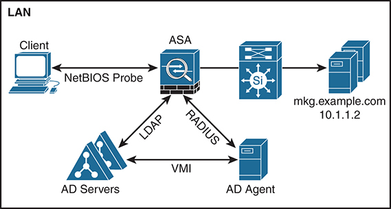
Figure 4-16 ASA-to-AD Communication
The ASA can be configured to communicate to multiple AD servers for redundancy. Likewise, multiple AD agents can be deployed to eliminate a single point dependency.
Identity Firewall Configuration
As noted earlier in this chapter, the ASA needs to be configured with AD server information and the AD agent. For proper operation, the ASA needs to bind to the correct directory name (DN) information in Active Directory. The configuration steps are shown here:
Step 1. Configure the ASA to speak LDAP, bind to DN, and provide authentication credentials to query the LDAP directory, as shown in Example 4-19.
Example 4-19 ASA LDAP Active Directory Configuration
asa(config)# aaa-server adserver protocol ldap
asa(config-aaa-server-group)# aaa-server adserver (interface) host <ip address>
asa(config-aaa-server-host)# ldap-base-dn DC=SAMPLE,DC=com
asa(config-aaa-server-host)# ldap-scope subtree
asa(config-aaa-server-host)# ldap-login-password <password>
asa(config-aaa-server-host)# ldap-login-dn cn=user1,DC-SAMPLE,DC=com
asa(config-aaa-server-host)# server-type microsoft
asa(config-aaa-server-host)# ldap-group-base-dn OU=Sample Groups,DC=SAMPLE,DC=com
asa(config-aaa-server-host)# ldap-over-ssl enable
asa(config-aaa-server-host)# server-port 389
Step 2. Configure the ASA to communicate using RADIUS to the AD agent, as shown in Example 4-20.
Example 4-20 ASA RADIUS-to-AD Agent Configuration
asa(config)# aaa-server adagent protocol radius
asa(config-aaa-server-group)# ad-agent-mode
asa(config-aaa-server-group)# exit
asa(config)# aaa-server adagent (interface) host <ip address>
asa(config-aaa-server-host)# key <key>
asa(config-aaa-server-host)# exit
asa(config)# user-identity ad-agent aaa-server adagent
Step 3. Optionally test the AD agent communication with the ASA to verify proper configuration:
asa(config-aaa-server-host)# test aaa-server ad-agent adagent
Step 4. Enable the Identity Firewall feature on the ASA:
asa(config)# user-identity enable
Once the Identity Firewall feature is enabled, the ASA can apply user- and group-based policy decisions through the use of extended ACLs. Example 4-21 shows a simple Identity Firewall–based ACL.
Example 4-21 ASA Group-Based Access List
access-list 100 ex permit ip user ACMEGroup1 any any
access-list 100 ex deny ip user ACMEGroup2 any any
access-list 100 ex deny any any
access-group 100 in interface inside
Security Group Tags (SGTs)
Mobile users and virtualized workload mobility have created challenges for security policies based on static mechanisms such as IP addresses. Cisco created an architecture called TrustSec that combines user and group identity information with a centralized access control policy. An SGT is a 16-bit number passed as metadata between Cisco devices. The ASA supports the capability to be part of a TrustSec network, where access decisions are based upon this SGT metadata.
Note For more information on Cisco TrustSec, see http://www.cisco.com/c/en/us/solutions/enterprise-networks/trustsec/index.html.
Three components make up the ASA configuration in TrustSec:
![]() The ASA
The ASA
![]() The Identity Services Engine (ISE)
The Identity Services Engine (ISE)
![]() The SGT Exchange Protocol (SXP)
The SGT Exchange Protocol (SXP)
The ASA creates a secure channel via RADIUS with ISE in order to download the TrustSec environment data. This security group table contains the SGT-to-group name mappings. SXP is the method by which the IP-SGT bindings are communicated to and from the ASA. It was developed as a control plane to extend the TrustSec network to devices that don’t natively support hardware tagging. SXP is not required, however, as the IP-SGT bindings can optionally be manually configured. For scalability reasons, SXP is recommended for larger networks. ASA has supported SXPv3 since the 9.6 release and is backward-compatible with other SXP versions.
Note Security Exchange Protocol (SXP) is now an IETF standard; see https://tools.ietf.org/html/draft-smith-kandula-sxp-00.
TrustSec Configuration
Much as with Identity Firewall, the ASA requires some initial configuration steps, as outlined here:
Step 1. Configure the ASA to speak RADIUS to the ISE server and configure it to work with TrustSec:
asa(config)# aaa-server ISEserver protocol radius
asa(config-aaa-server-group)# aaa-server ISEserver {interface} host {address}
asa(config)# cts server-group ISEserver
Step 2. Create the trusted relationship with ISE by importing a PAC file from ISE onto the ASA:
asa(config)# cts import-pac path password password
Step 3. Enable SXP on the ASA and connect to a peer so that ASA is configured to receive updates from the peer:
asa(config)# cts sxp connection peer peer password default mode local listener
When the ASA is configured to receive IP-SGT binding information, access control policies may be enabled to utilize the security group information contained within the tags. Any feature that uses extended ACLs (unless otherwise unsupported) can take advantage of these mappings. To verify that SXP is working properly, the best practice is to refresh the environment data received from ISE via the show cts environment-data command on the ASA. Example 4-22 shows sample output from this command.
Example 4-22 ASA SXP Operation Verification
asa(config)# show cts environment-data

CTS Environment Data
Status:                    Active
Last download attempt:     Successful
Environment Data Lifetime: 86400 secs
Last update time:          05:05:16 UTC Apr 14 2017
Env-data expires in:       0:23:56:15 (dd:hr:mm:sec)
Env-data refreshes in:     0:23:46:15 (dd:hr:mm:sec)
You are now ready to create an ACL on the ASA that filters traffic based on the security group information. In this example, only ICMP traffic from security-group 3 to security-group 2 is allowed:
access-list ICMP_ONLY extended permit icmp security-group tag 3 any security-group 2 any
access-group ICMP_ONLY in interface inside
An alternative option is to use the actual group names in the ACL instead of the tag numbers, as shown previously. Assume that security-group 3 maps to a group called SALES, and security-group 2 represents a group called ENGINEERING:
access-list ICMP_ONLY extended permit icmp security-group name SALES any security-group name ENGINEERING any access-group inside in interface inside
TrustSec builds on Identity Firewall as it allows for a centralized access control policy on ISE to be applied in a distributed manner throughout the Cisco network. The ASA can enforce these policies, which provides a more scalable policy than is available by replicating ACLs on every perimeter network device.
Advanced Firewall Tuning
Given its role in the network, the firewall is both a device for enforcing policy and a means of protecting services from external exploitation. This section explores both types of features on the ASA and how they are configured.
A common configuration on an Internet-facing ASA is to protect externally reachable servers from exploitation. Most of the features needed for this protection are enabled by default and can be configured to be much more aggressive.
Every time a new connection is created in the ASA, several settings can be configured. The default settings for maximum connection limits, timeouts, and TCP normalization are appropriate for the majority of deployments. For example, the ASA by default randomizes the ISN of TCP sequence numbers for connections. This makes it more difficult for an attacker to predict the next ISN for a new connection in order to hijack the session. This can be disabled per traffic class, if necessary, through the MPF.
TCP Intercept is a feature that protects hosts from denial-of-service (DoS) attacks. These attacks attempt to overwhelm a device with TCP SYN traffic that often is generated from spoofed IP addresses. If the DoS traffic rate is high enough, the target host is not able to respond to legitimate connection requests.
By design, the ASA responds on behalf of hosts and responds to the initial TCP SYN for a new connection with an appropriate SYN ACK. When the three-way handshake is complete, the ASA completes the connection and allows traffic to pass to the internal host. This process is called TCP Intercept, and these half-completed connections are known as embryonic connections.
Advanced Firewall Configuration
Sometimes default protection limits are not enough for high-value servers, which need more robust controls on inbound connections. The ASA uses a policy map to set these limits, as shown in this example, assuming two web servers, 10.1.1.5 and 10.1.1.6:
Step 1. Create an access list and define the class map and match criteria:
asa(config)# access-list SERVERS extended permit tcp any host 10.1.1.5 eq http
asa(config)# access-list SERVERS extended permit tcp any host 10.1.1.6 eq http
asa(config)# class-map protected-servers
asa(config-cmap)# match access-list SERVERS
Step 2. Define the policy map and apply the class to it:
asa(config)# policy-map DOS_policy
asa(config-pmap)# class protected-servers
Step 3. Set the embryonic connection limits to a maximum of 100, limited to 50 per client:
asa(config-pmap-c)# set connection embryonic-conn-max 100
asa(config-pmap-c)# set connection per-client-embryonic-max 50
Step 4. Apply the service policy to the outside interface:
asa(config)# service-policy DOS_policy in interface outside
TCP State Bypass
In some cases, it may be necessary to turn off ASA state checking when asymmetric traffic flows are present. Asymmetric flows can occur when connections are created through one firewall but return through a different firewall, as shown in Figure 4-17.
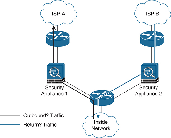
Figure 4-17 ASA Asymmetric Flow
By default, a stateful device drops this traffic by design, but you can disable this functionality on the ASA. In Example 4-23, TCP state checking is turned off for any traffic originating from the 10.1.1.0/27 network.
Example 4-23 Disabling TCP State Checking on the ASA
asa(config)# access-list tcp_bypass extended permit tcp 10.1.1.0 255.255.255.224 any
asa(config)# class-map tcp_bypass
asa(config-cmap)# description "TCP traffic that bypasses stateful firewall"
asa(config-cmap)# match access-list tcp_bypass

asa(config-cmap)# policy-map tcp_bypass_policy
asa(config-pmap)# class tcp_bypass
asa(config-pmap-c)# set connection advanced-options tcp-state-bypass

asa(config-pmap-c)# service-policy tcp_bypass_policy outside
Policy Based Routing (PBR)
PBR on the ASA is a new feature that was introduced in the 9.4 release. PBR has long been available in IOS and is another routing feature that was imported into the ASA code train. As in IOS, in the ASA PBR creates a policy in which packets are sent to a destination that is not in the routing table. Packets matching the PBR policy effectively override the global routing table. PBR is commonly used when multiple egress paths are present and there is a need to differentiate routing policy. It is also used on the ASA to assign QoS values for traffic classification.
In the example shown in Figure 4-18, an ASA is connected to two service providers, A and B. There is a requirement for Host A to only use Provider A and Host B to only go through Provider B. PBR on the ASA allows this to happen.
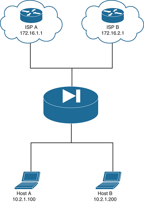
Figure 4-18 PBR on the ASA
Much as in IOS, with the ASA, route-map statements are used to define the match criteria and action to take. In this example, you set the next hop to the ISP gateway based on the host source address:
Step 1. Create an access list that defines the matching criteria. In this case you need an access list for each host:
asa(config)# access-list HOST_A extended permit ip host 10.2.1.100 any
asa(config)# access-list HOST_B extended permit ip host 10.2.1.200 any
Step 2. Create a route-map entry. Route-maps are processed in top-down order, using sequence numbers:
asa(config)# route-map PBR-MAP permit 10
asa(config-route-map)# match ip address HOST_A
Step 3. Create an action for matching traffic using the set keyword. In this example, you want Host A to use Provider A’s gateway address, 172.16.1.1:
asa(config-route-map)# set ip next-hop 172.16.1.1
Step 4. Create a route-map entry for Host B and set the next-hop address to Provider B:
asa(config)# route-map PBR-MAP permit 20
asa(config-route-map)# match ip address HOST_B
asa(config-route-map)# set ip next-hop 172.16.2.1
Step 5. Apply the policy to at least one interface:
asa(config)# interface Gigabit0/1
asa(config-int)# policy-route route-map PBR-MAP
Unmatched traffic falls through the policy map and is routed according to the global routing table.
Threat Detection
Threat detection is an ASA Layer 3/Layer 4 feature that analyzes and baselines traffic patterns in ASA code 8.04 and later. This analysis is used to protect both the ASA and the network devices behind it. It is intended for environments that don’t have dedicated deep-packet inspection (DPI) capabilities in place, such as an IDS or IPS.
Basic threat detection is enabled by default and tracks many different statistics, such as packet format, connection limits, incomplete sessions, and traffic dropped by an ACL, to name a few. Its performance impact is negligible, as it measures statistics for drop rates over a period of time. There are two configurable thresholds: the average rate and the burst rate. When a basic threat is detected, the ASA generates a syslog message as a result.
The show threat-detection rate command shows the average, current, trigger, and total events per category.
By using advanced threat detection, you can track traffic at the object level so the ASA has a concise picture for individual hosts, ports, and protocols. Only traffic that is going through the ASA is tracked; traffic destined for the ASA itself is not tracked, and only ACL statistics are enabled by default with advanced threat protection. Working with another ASA feature, TCP Intercept, advanced threat detection can track more detailed statistics on top servers to be considered under attack. Various rate limits can be fine-tuned to provide more useful information.
Advanced threat detection is optionally enabled via the threat-detection statistics command, as shown in Example 4-24.
Example 4-24 ASA Threat Detection Configuration
asa(config)# threat-detection statistics ?
configure mode commands/options:
 access-list     Keyword to specify access-list statistics
 host            Keyword to specify IP statistics
 port            Keyword to specify port statistics
 protocol        Keyword to specify protocol statistics
 tcp-intercept   Trace tcp intercept statistics
Care should be taken on what is measured via advanced threat detection as its usage can be resource-intensive. For a good view of how much memory is consumed by threat detection, use the show memory app-cache threat-detection [detail] command.
A third category of threat detection is designed to mitigate risks by malicious network scanning. It is enabled via the threat-detection scanning-threat command. Much as with basic threat detection, capture rates can be adjusted via threat-detection rate. Using the optional shun keyword with scanning threat detection allows the ASA to temporarily block traffic from the attacker. The ASA shunning feature allows for exceptions to the shunning action but should be used with care on a production network.
Troubleshooting the ASA
Troubleshooting the ASA is easier if you have an understanding of some of the built-in tools and show commands. In addition, having an understanding of the life of a packet through the ASA is helpful. Much as with other devices, for the ASA to forward traffic, it needs to be able to determine some basic networking information, such as egress interface and the routing next hop. This is obvious to any experienced network engineer. What may not be so obvious, however, is the order in which these checks are applied.
With few exceptions, the ASA checks these items in the following order:
1. Route lookup
2. Ingress access list lookup
3. NAT rules
4. Egress access list lookup
5. Redirection to an internal module (if present)
6. Egress interface
The following are some of the useful commands to help determine packet flow details at each stage:
show interface
show conn
show access-list
show xlate
show service-policy inspect
show run static
show run nat
show run global
show nat
show route
show arp
Note Using syslog is also a useful method for tracking connection state. For more information, see Cisco ASA Series Syslog Messages on cisco.com.
As mentioned earlier in this chapter, ASA Packet Tracer is an excellent built-in troubleshooting utility that can be accessed via the command line or via ASDM. It provides a detailed step-by-step walkthrough of a virtual packet in the ASA, from ingress to egress, and allows real-time debugging when source, destination, and port and protocol information are input.
Packet Tracer command line syntax is as follows:
packet-tracer input [src_int] protocol src_addr src_port dest_addr dest_port [detailed] [xml]
Example 4-25 shows sample output from the Packet Tracer utility.
Example 4-25 ASA Packet Tracer Output
asa(config)# packet-tracer input inside tcp 10.2.1.10 53 8.8.8.8 53

Phase: 1
Type: ROUTE-LOOKUP
Subtype: Resolve Egress Interface
Result: ALLOW
Config:
Additional Information:
found next-hop 172.16.3.3 using egress ifc  outside

Phase: 2
Type: NAT
Subtype:
Result: ALLOW
Config:
object network Lab-Mgmt-Net
 nat (any,outside) dynamic interface
Additional Information:
Dynamic translate 10.2.1.10/53 to 172.16.1.100/53

Phase: 3
Type: NAT
Subtype: per-session
Result: ALLOW
Config:
Additional Information:

Phase: 4
Type: IP-OPTIONS
Subtype:
Result: ALLOW
Config:
Additional Information:

Phase: 5
Type: NAT
Subtype: per-session
Result: ALLOW
Config:
Additional Information:

Phase: 6
Type: IP-OPTIONS
Subtype:
Result: ALLOW
Config:
Additional Information:

Phase: 7
Type: FLOW-CREATION
Subtype:
Result: ALLOW
Config:
Additional Information:
New flow created with id 304980, packet dispatched to next module

Result:
input-interface: inside
input-status: up
input-line-status: up
output-interface: outside
output-status: up
output-line-status: up
Action: allow
The ASDM Packet Tracer under the Tools menu provides a visual tool for troubleshooting. Functionally, it works the same as the command-line version. The ASDM Packet Tracer is shown in Figure 4-19.
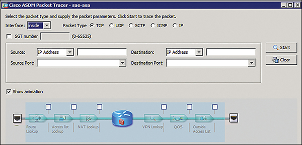
Figure 4-19 ASDM Packet Tracer Utility
Packet Capture
ASA Packet Capture is available at the command line or via a tool in ASDM. Only its command-line use is discussed here. As the name implies, Packet Capture is an ASA troubleshooting tool for capturing live packets as they transit the firewall. Unlike with a traditional SPAN port, ASA Packet Capture can record traffic on the ASA backplane as well as traffic that is dropped due to policy (asp-drop). Both of these are extremely useful when troubleshooting the ASA. An additional benefit is that you can export the Packet Capture file as a .pcap for detailed analysis via Wireshark by pointing any browser to https://ASA_IP/admin/capture/capture_name/pcap.
For more detailed troubleshooting, the Packet Capture utility offers different capture types. Some of the most useful ones are listed here:
![]() asa_dataplane: Useful for tracking packets between the ASA and a service module.
asa_dataplane: Useful for tracking packets between the ASA and a service module.
![]() asp-drop: The accelerated security path is useful for showing packets dropped by policy.
asp-drop: The accelerated security path is useful for showing packets dropped by policy.
![]() ethernet-type: As implied, this is useful for troubleshooting EtherType issues.
ethernet-type: As implied, this is useful for troubleshooting EtherType issues.
![]() real-time: Use this with care on slow console connections to avoid overwhelming the serial buffer.
real-time: Use this with care on slow console connections to avoid overwhelming the serial buffer.
![]() trace: Similar to the Packet Tracer feature, this shows a step-by-step method for each packet.
trace: Similar to the Packet Tracer feature, this shows a step-by-step method for each packet.
Packet Capture Configuration
The configuration of Packet Capture consists of creating a capture file, binding it to an interface, and optionally providing matching criteria.
This is an example of a capture file named capin on the inside interface matching traffic between hosts 192.168.10.10 and 203.0.113.3:
asa# capture capin interface inside match ip 192.168.10.10 255.255.255.255
203.0.113.3 255.255.255.255
Optionally, another capture file could be created on the ASA outside interface. To view the capture, simply issue a show capture command that references the specified capture file (for example, capin).
To clear the buffer, use the clear capture capture_name command. This clears the contents but keeps the capture active. To stop the capture, use the no version of the command.
Summary
Since its release in 2005, the ASA firewall has continually added new features to expand its reach. It now has physical, virtual, and cloud-based versions that serve a wide range of customer deployment scenarios. This chapter highlights many of the core features of the ASA, including advanced tuning and configuration.
This chapter starts with the initial ASA configuration, highlighting the usage of security levels and zones and how a virtual lab ASA could be beneficial for CCIE study. Routing and transparent mode are covered, with common deployment scenarios and configuration provided for each. The benefits of multi-context mode and a treatment of the two high-availability options and ASA clustering are discussed. Wide routing protocol support is still a recent development on the ASA. Use cases and configuration examples are provided.
The importance of NAT cannot be understated in today’s networks. The ASA offers a robust set of NAT configuration options, which give it maximum flexibility for advanced use cases. Best practices for troubleshooting NAT are shared in this chapter, as well as techniques to validate its operation.
Advanced ASA features such as policy maps and their usage are introduced in this chapter. The chapter also covers ways to manipulate traffic on the ASA, such as TCP state bypass and the built-in threat detection capabilities.
This chapter also covers general troubleshooting such as Packet Tracer and Packet Capture, and how they can be effective in debugging a broken firewall. The configuration examples in this chapter combined with hands-on practice will help a CCIE candidate maximize preparation for the lab exam.
References
“ASA Configuration Guides,” https://www.cisco.com/c/en/us/support/security/asa-5500-series-next-generation-firewalls/products-installation-and-configuration-guides-list.html
“Release Notes for the ASA Series, 9.4(x),” https://www.cisco.com/c/en/us/td/docs/security/asa/asa94/release/notes/asarn94.html
“Cisco Firewalling Support Forums,” https://supportforums.cisco.com/t5/firewalling/bd-p/5966-discussions-firewalling
“Configuring Network Address Translation,” https://www.cisco.com/c/en/us/td/docs/security/security_management/cisco_security_manager/security_manager/4-1/user/guide/CSMUserGuide_wrapper/NATchap.pdf
“ASA 8.3 NAT Configuration” YouTube, https://www.youtube.com/watch?v=R6TMlH9U2pE
“Cisco Virtual Internet Routing Lab,” https://learningnetworkstore.cisco.com/virtual-internet-routing-lab-virl/cisco-personal-edition-pe-20-nodes-virl-20
“ASA NAT Migration to Version 8.3,” https://www.cisco.com/c/en/us/td/docs/security/asa/asa83/upgrading/migrating.html
“Cisco TrustSec Overview,” http://www.cisco.com/c/en/us/solutions/enterprise-networks/trustsec/index.html.