Chapter 3
Wireless Security
This chapter provides details about wireless security that a security professional needs to understand. This chapter explores the history, standards, and basics of wireless, along with advanced topics related to securing wireless LANs. You will learn how to connect a wireless access point (WAP) to a wireless LAN controller (WLC) and how to secure the wireless data plane and management plane for unified deployments.
What Is Wireless?
Today it is hard to think about what it was like to be tethered to a desk by an Ethernet cable. Wireless communication in businesses and homes is now pervasive and critical to productivity and our daily lives. Wireless communication at a basic level is the ability to communicate between computers without wires, and it typically involves wireless access points (APs) and stations (STA).
Wireless Standards
Since 1997, the Institute of Electrical and Electronics Engineers (IEEE) has been defining 802.11 standards for what we know today as the wireless local area network (WLAN). You might also use the term Wi-Fi, which comes from the Wi-Fi Alliance, the organization responsible for ensuring its members follow the IEEE standards and certifying products to ensure interoperability. Thanks to this standardization, when you buy a WAP from one company and a wireless adapter or interface from another company, they can actually work together.
802.11 Standards
Over the years, 802.11 has advanced a lot. Most users and organizations purchase the latest and greatest WAP, and they get better performance, reliability, and coverage. The IEEE and Wi-Fi Alliance have been relentlessly improving the way wireless stations communicate with access points to achieve these results. One way we have gained additional speed is by increasing the bandwidth. You can equate increasing bandwidth to adding additional lanes on a highway. The other primary method of increasing speeds is by increasing the number of antennas being used simultaneously. Using multiple antennas, or multiple-input, multiple-output (MIMO) technology, is the equivalent of adding multiple roads between the source and destination. Table 3-1 provides a summary of the standards changes over the years since the 802.11 standards were introduced in 1997.
Table 3-1 802.11 Standards
Standard |
Year |
Band |
Bandwidth |
Speed |
802.11 |
1997 |
2.4 GHz |
22 MHz |
2 Mbps |
802.11a |
1999 |
5 GHz |
20 MHz |
54 Mbps |
802.11b |
1999 |
2.4 GHz |
22 MHz |
11 Mbps |
802.11g |
2003 |
2.4 GHz |
20 MHz |
54 Mbps |
802.11n |
2009 |
2.4 and 5 GHz |
Up to 40 MHz |
Up to 300 Mbps |
802.11ac Wave 1 |
2013 |
2.4 and 5 GHz |
Up to 80 MHz |
Up to 1.3 Gbps |
802.11ac Wave 2 |
2016 |
2.4 and 5 GHz |
Up to 160 MHz |
Up to 2.3 Gbps |
802.11 MAC Frame Formats
802.11 is a little more advanced at the MAC layer than the 802.3 Ethernet specification. Understanding the different frames will help you understand how to secure WLANs.
Figure 3-1 illustrates the 802.11 MAC frame format, including the control frame information.

Figure 3-1 802.11 Frame Format
There are three types of frames defined in the standard:
![]() Control frame: This type of frame sets up data exchanges and facilitates the data frames.
Control frame: This type of frame sets up data exchanges and facilitates the data frames.
![]() Management frame: This type of frame facilitates WLAN connectivity, authentication, and status.
Management frame: This type of frame facilitates WLAN connectivity, authentication, and status.
![]() Data frame: This type of frame handles station data between the transmitter and receiver.
Data frame: This type of frame handles station data between the transmitter and receiver.
Association and Authentication
Two things must take place for a station to be connected and forward data: association and authentication. Figure 3-2 illustrates a station and WAP exchanging a series of management frames in order to get to an authenticated and associated state.

Figure 3-2 Station and WAP Connection Process
The following steps are involved in the association and authentication process:
Step 1. Beacon frames are transmitted periodically to announce the presence of a WLAN and contain all information about one or more Service Set Identifiers (SSIDs), data rates, channels, security ciphers, key management, and so on.
Step 2. The STA sends a probe request.
Step 3. The AP sends a probe response to the STA.
Step 4. The STA sends an authentication request frame to the AP. (Note that this assumes Open Authentication.)
Step 5. The AP send an authentication response frame to the STA.
Step 6. The STA sends an association request to the AP with security.
Step 7. The AP send an association response frame to the STA.
Note Do not confuse wireless authentication with 802.1X authentication. 802.1X comes after the full 802.11 association and authentication between the AP and STA.
Autonomous Versus Controller-Based WLANs
Early wireless deployments all had individual APs with stations or clients directly connected. Such APs are called autonomous APs because they act independently of each other. Organizations very quickly ran into issues trying to manage tens or hundreds of autonomous APs. The wireless LAN controller was created to address the management, scalability, and reliability issues previously seen with autonomous APs. With controller-based architectures, you can build a WLAN with hundreds or thousands of APs and still centrally administer, operate, and troubleshoot. Today, the only autonomous APs that are being deployed are typically for point-to-point or point-to-multiple bridges. Therefore, this chapter focuses on and assumes a controller-based deployment.
WLC Fundamentals
WLCs support centralized management functions to deliver the following:
![]() WLAN management for centrally creating SSIDs and associated settings
WLAN management for centrally creating SSIDs and associated settings
![]() Radio resource management (RRM), which includes the following:
Radio resource management (RRM), which includes the following:
![]() Transmit power control (TPC), which sets the transmit power of each AP to maximize the coverage and minimize co-channel interference
Transmit power control (TPC), which sets the transmit power of each AP to maximize the coverage and minimize co-channel interference
![]() Dynamic channel assignment (DCA), which evaluates and dynamically manages channel assignments
Dynamic channel assignment (DCA), which evaluates and dynamically manages channel assignments
![]() Coverage hole detection (CHD), which detects coverage holes and mitigates them
Coverage hole detection (CHD), which detects coverage holes and mitigates them
![]() Mobility management for managing roaming between APs and controllers
Mobility management for managing roaming between APs and controllers
![]() Access point configuration
Access point configuration
![]() Security settings and wireless intrusion prevention system (wIPS) capabilities
Security settings and wireless intrusion prevention system (wIPS) capabilities
![]() Network-wide quality of service (QoS) for voice and video
Network-wide quality of service (QoS) for voice and video
![]() Operations and troubleshooting
Operations and troubleshooting
Note For more information about configuring, designing, and deploying WLCs, read Controller-Based Wireless LAN Fundamentals: An End-to-End Reference Guide to Design, Deploy, Manage, and Secure 802.11 Wireless Networks by Jeff Smith, Jake Woodhams, and Robert Marg (Cisco Press).
CAPWAP Overview
Control and Provisioning of Wireless Access Points (CAPWAP) is a standard protocol that enables a WLC to manage APs. CAPWAP is based on the Lightweight Access Point Protocol (LWAPP) that was originally designed and used by Cisco. CAPWAP is defined in the following Internet Engineering Task Force (IETF) Requests for Comments (RFCs):
![]() RFC 4564 defines the objectives for the CAPWAP protocol.
RFC 4564 defines the objectives for the CAPWAP protocol.
![]() RFC 5418 covers threat analysis for IEEE 802.11 deployments.
RFC 5418 covers threat analysis for IEEE 802.11 deployments.
![]() RFC 5415 defines the CAPWAP protocol specifications.
RFC 5415 defines the CAPWAP protocol specifications.
CAPWAP carries control and data traffic between the AP and the WLC. The control plane is Datagram Transport Layer Security (DTLS)–encrypted and uses UDP port 5246. The data plane is optionally DTLS encrypted and uses UDP port 5247. The CAPWAP state machine, which is used for managing the connection between AP and controller, is shown in Figure 3-3.
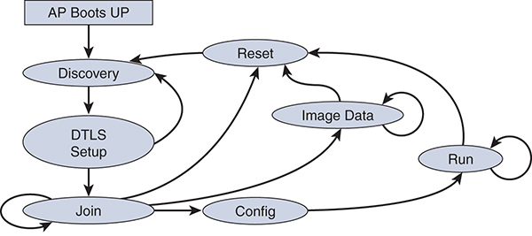
Figure 3-3 CAPWAP State Machine
Access Point Discovery Process
Making sure access points join up to a WLC is an important step in any deployment. Understanding the details of this process is critical in troubleshooting connection problems. In local AP mode (discussed in the next section), if the AP loses its connection or cannot connect to the WLC, then no SSIDs will be active, and traffic will not be forwarded by the AP until it can successfully connect.
After an AP gets an IP address using DHCP or uses a previously assigned static IP address, the AP uses one of the following methods to connect to a WLC.
![]() Layer 3 CAPWAP discovery: This feature can be enabled on different subnets from the access point and uses either broadcast IPv4 or IPv6 addresses and UDP packets. Any WLC that is Layer 2 adjacent to the AP will respond to the request.
Layer 3 CAPWAP discovery: This feature can be enabled on different subnets from the access point and uses either broadcast IPv4 or IPv6 addresses and UDP packets. Any WLC that is Layer 2 adjacent to the AP will respond to the request.
![]() CAPWAP multicast discovery: Broadcast does not exist in IPv6 addresses. An access point sends a CAPWAP discovery message to all of the controller’s multicast addresses (FF01::18C). The controller receives the IPv6 discovery request from the AP only if it is in the same Layer 2 segment and sends back the IPv6 discovery response.
CAPWAP multicast discovery: Broadcast does not exist in IPv6 addresses. An access point sends a CAPWAP discovery message to all of the controller’s multicast addresses (FF01::18C). The controller receives the IPv6 discovery request from the AP only if it is in the same Layer 2 segment and sends back the IPv6 discovery response.
![]() Locally stored controller IPv4 or IPv6 address discovery: If the access point was previously associated to a controller, the IPv4 or IPv6 addresses of the primary, secondary, and tertiary controllers are stored in the access point’s nonvolatile memory. This process of storing controller IPv4 or IPv6 addresses on an access point for later deployment is called priming the access point.
Locally stored controller IPv4 or IPv6 address discovery: If the access point was previously associated to a controller, the IPv4 or IPv6 addresses of the primary, secondary, and tertiary controllers are stored in the access point’s nonvolatile memory. This process of storing controller IPv4 or IPv6 addresses on an access point for later deployment is called priming the access point.
![]() DHCP server discovery using option 43: DHCP option 43 provides controller IPv4 addresses to the access points. Cisco switches support a DHCP server option that is typically used for this capability.
DHCP server discovery using option 43: DHCP option 43 provides controller IPv4 addresses to the access points. Cisco switches support a DHCP server option that is typically used for this capability.
![]() DHCP server discovery using option 52: DHCP option 52 allows an AP to discover the IPv6 address of the controller to which it connects. As part of the DHCPv6 messages, the DHCP server provides the controller’s management with an IPv6 address.
DHCP server discovery using option 52: DHCP option 52 allows an AP to discover the IPv6 address of the controller to which it connects. As part of the DHCPv6 messages, the DHCP server provides the controller’s management with an IPv6 address.
![]() DNS discovery: The AP can discover controllers through your DNS server. You must configure your DNS server to return controller IPv4 and IPv6 addresses in response to CISCO-LWAPP-CONTROLLER.localdomain or CISCO-CAPWAP-CONTROLLER.localdomain, where localdomain is the access point domain name.
DNS discovery: The AP can discover controllers through your DNS server. You must configure your DNS server to return controller IPv4 and IPv6 addresses in response to CISCO-LWAPP-CONTROLLER.localdomain or CISCO-CAPWAP-CONTROLLER.localdomain, where localdomain is the access point domain name.
It is recommended for predictability and stability that you manually insert the primary, secondary, and tertiary controllers into Wireless > Access Points > All APs > Details for AP Name > High Availability, as shown in Figure 3-4. This is recommended regardless of the discovery method the AP uses.
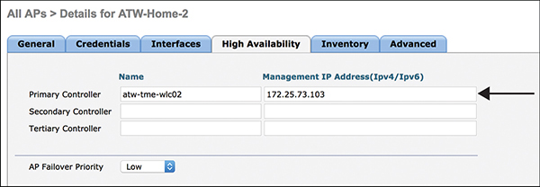
Figure 3-4 Manual WLC Definition
You may also define backup WLCs for all APs by going to Wireless > Access Points > Global Configuration, as shown in Figure 3-5. You can configure primary and secondary backup controllers for all access points (which are used if primary, secondary, or tertiary controllers are not responsive) in this order: primary, secondary, tertiary, primary backup, and secondary backup.
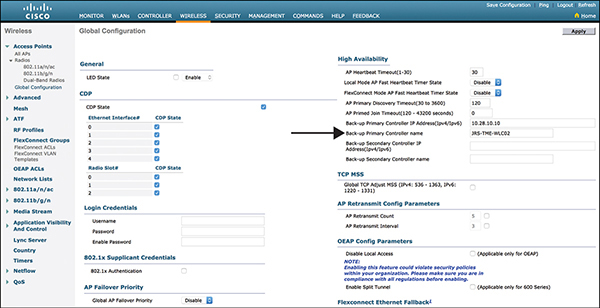
Figure 3-5 WLC Primary and Secondary Definitions for all APs
AP Modes
Access points can run in different operating modes. The following are the options to specify the operating modes of access points:
![]() Local: This is the default (unless you are running a flex controller) and most commonly deployed mode. The AP uses its CAPWAP tunnel for data forwarding and management (authentication, roaming, and so on). All client traffic is centrally switched by the controller, meaning the controller forwards the traffic from its data interfaces. Lightweight Access Points (LAPs) are sometimes referred to as “dumb” APs, primarily due to the fact that they do very little thinking on their own when in local mode.
Local: This is the default (unless you are running a flex controller) and most commonly deployed mode. The AP uses its CAPWAP tunnel for data forwarding and management (authentication, roaming, and so on). All client traffic is centrally switched by the controller, meaning the controller forwards the traffic from its data interfaces. Lightweight Access Points (LAPs) are sometimes referred to as “dumb” APs, primarily due to the fact that they do very little thinking on their own when in local mode.
![]() FlexConnect: This mode is typical for branch and remote office deployments. It allows for central (at the WLC) or local (at the AP) switched traffic. More details can be found in the next session, “FlexConnect Access Points.”
FlexConnect: This mode is typical for branch and remote office deployments. It allows for central (at the WLC) or local (at the AP) switched traffic. More details can be found in the next session, “FlexConnect Access Points.”
![]() Bridge: This mode is for using the AP to connect to a root AP.
Bridge: This mode is for using the AP to connect to a root AP.
![]() SE-Connect: This mode allows you to connect to a spectrum expert, and it allows the access point to perform spectrum intelligence.
SE-Connect: This mode allows you to connect to a spectrum expert, and it allows the access point to perform spectrum intelligence.
![]() Monitor: This mode is the monitor-only mode.
Monitor: This mode is the monitor-only mode.
![]() Sniffer: The access point starts sniffing the air on a given channel. It captures and forwards all the packets from the clients on that channel to a remote machine that runs Airopeek or Wireshark (packet analyzers for IEEE 802.11 wireless LANs). It includes information on the time stamp, signal strength, packet size, and so on.
Sniffer: The access point starts sniffing the air on a given channel. It captures and forwards all the packets from the clients on that channel to a remote machine that runs Airopeek or Wireshark (packet analyzers for IEEE 802.11 wireless LANs). It includes information on the time stamp, signal strength, packet size, and so on.
![]() Rogue Detector: This mode monitors the rogue APs on the wire. It does not transmit or receive frames over the air or contain rogue APs.
Rogue Detector: This mode monitors the rogue APs on the wire. It does not transmit or receive frames over the air or contain rogue APs.
Access points also have an option to configure the AP submode:
![]() wIPS: The AP is in local, FlexConnect, or monitor mode, and the wIPS submode is configured on the access point.
wIPS: The AP is in local, FlexConnect, or monitor mode, and the wIPS submode is configured on the access point.
![]() None: The AP is in local or FlexConnect mode, and the wIPS submode is not configured on the AP.
None: The AP is in local or FlexConnect mode, and the wIPS submode is not configured on the AP.
FlexConnect Access Points
FlexConnect (previously known as Hybrid Remote Edge Access Point [H-REAP]) is a wireless solution that can switch client data traffic locally and perform client authentication locally when the connection to the controller is lost. When a client is connected to the controller, it can also send traffic back to the controller. In connected mode, the FlexConnect access point can also perform local authentication.
Locally switched WLANs map wireless user traffic to VLANs to an adjacent switch by using 802.1Q trunking. If desired, one or more WLANs can be mapped to the same local 802.1Q VLAN. All AP control/management-related traffic is sent to the centralized WLC separately using CAPWAP.
Central switched WLANs use CAPWAP to tunnel both the wireless user traffic and all control traffic to the centralized WLC, where the user traffic is mapped to a dynamic interface/VLAN on the WLC. This is the normal CAPWAP mode of operation.
On FlexConnect access points, two types of WLANs can be configured:
![]() Connected mode: The WLC is reachable. In this mode, the FlexConnect AP has CAPWAP connectivity with its WLC.
Connected mode: The WLC is reachable. In this mode, the FlexConnect AP has CAPWAP connectivity with its WLC.
![]() Standalone mode: The WLC is unreachable. The FlexConnect AP has lost or failed to establish CAPWAP connectivity with its WLC.
Standalone mode: The WLC is unreachable. The FlexConnect AP has lost or failed to establish CAPWAP connectivity with its WLC.
You can have one WLAN that is centrally switched (for example, for a guest) and still have a locally switched WLAN (for example, for an employee). When the FlexConnect AP goes into standalone mode, the locally switched WLAN still functions, and the centrally switched WLAN fails.
FlexConnect groups allow you to group together APs in a branch or remote office that share common configuration items, such as the following:
![]() Local/backup RADIUS servers’ IP/keys
Local/backup RADIUS servers’ IP/keys
![]() Local user and EAP authentication
Local user and EAP authentication
![]() Image upgrade
Image upgrade
![]() ACL mappings, including AAA VLAN-ACL mappings and WLAN-ACL mappings
ACL mappings, including AAA VLAN-ACL mappings and WLAN-ACL mappings
![]() Central DHCP settings
Central DHCP settings
![]() WLAN-VLAN mappings, which allows override of the WLAN VLAN/interface for the group
WLAN-VLAN mappings, which allows override of the WLAN VLAN/interface for the group
![]() WLAN-AVC mappings
WLAN-AVC mappings
Figure 3-6 illustrates some of the options configurable for FlexConnect groups.

Figure 3-6 FlexConnect Groups
FlexConnect ACLs allow for filtering of traffic on FlexConnect APs and groups. The same configuration options exist for FlexConnect ACLs as for regular ACLs.
Guest Anchor Controllers
It is common for a wireless deployment to have a dedicated guest SSID to allow for visitors, contractors, or guests to connect to the Internet. One challenge is that typically an organization does not want to terminate guest users on the inside of its network. You can use anchor controllers to create a tunnel from the WLC in the core or campus of your network to an isolated network, such as a demilitarized zone (DMZ), as illustrated in Figure 3-7. The WLC uses Ethernet over IP (EoIP) tunnels to logically segment and transport the guest traffic between remote/foreign and anchor controllers. The original guest’s Ethernet frame is maintained across CAPWAP and EoIP tunnels. Other traffic on other SSIDs (employees, for example) is still locally bridged at the remote controller on the corresponding VLAN. Security features such as web authentication and ACLs are applied to the session at the anchor controller.
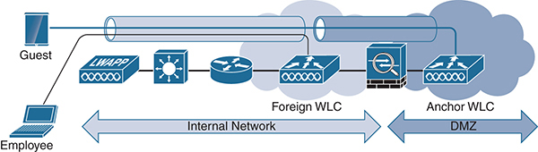
Figure 3-7 Guest Anchor Controller
When building a connection from a foreign controller to an anchor controller, IP port 97 for EoIP packets and UDP port 16666 for mobility control and new mobility data must be opened bidirectionally on any firewalls or packet filtering devices.
To create a guest anchor controller, perform the following steps:
Step 1. Go to Controller > General > Default Mobility Domain Name and RF Group Name and ensure that the anchor and foreign WLC are in different mobility groups (see Figure 3-8).

Figure 3-8 Mobility Group Configuration
Step 2. Go to Controller > Mobility Management > Mobility Groups > New and add the anchor controller to the foreign controller and add the foreign controller to the anchor controller mobility group members (see Figures 3-9 and 3-10).
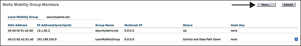
Figure 3-9 Adding a Mobility Group Member

Step 3. Go to Controller > Interfaces > New and add a VLAN on the anchor controller for guest users.
Step 4. Go to WLANs > Mobility Anchors > New and configure the WLAN on the anchor WLC’s mobility anchor to be local. Figures 3-11 and 3-12 show where to add the local mapping on the anchor WLC.

Figure 3-11 Configuring a Mobility Anchor on the WLAN

Figure 3-12 Mobility Anchor Create on the Anchor Controller
Step 5. Add the anchor controller’s IP to the foreign controllers as shown in Figure 3-13.

Figure 3-13 Mobility Anchor Created on the Foreign Controller
One guest anchor controller can terminate up to 71 EoIP tunnels from internal WLAN controllers. This capacity is the same across models of the Cisco WLC except the 2504. The 2504 controller can terminate up to 15 EoIP tunnels. More than one guest anchor controller can be configured if additional tunnels are required. EoIP tunnels are counted per WLAN controller, independently of the number of tunneled WLANs or SSIDs in each EoIP.
Wireless Security Overview
As adoption of wireless became popular, security concerns were immediately raised. Wireless needed to address who or what can use a WLAN (authentication), and it needed to be able to provide privacy and integrity for wireless data (encryption).
WEP
The initial attempt to address wireless security and data privacy was Wired Equivalent Privacy (WEP). WEP is based on the RC4 symmetric stream cipher. (For more information on stream versus block ciphers, see Integrated Security Technologies and Solutions, Volume II.) A symmetric encryption assumes the same WEP keys on both sides, either 40 or 104 bits in length and statically configured on the client and WAP. Symmetric encryption was chosen because of the low computational power required. WEP uses a 24-bit initialization vector (IV), which is concatenated to the key before being processed by the RC4 cipher. WEP only encrypts the data/payload and the integrity check value (ICV). WEP can use open or shared-key authentication. The default is open. Shared-key authentication is a standard challenge-and-response mechanism that makes use of WEP and a shared secret key to provide authentication. Upon encrypting the challenge text with WEP using the shared secret key, the authenticating client returns the encrypted challenge text to the access point for verification. Authentication succeeds if the access point decrypts the same challenge text. Shared-key authentication is used only with WEP.
WEP was found to be insecure because of its relatively short IVs and static keys. The RC4 encryption algorithm has nothing to do with the major flaws. By having a 24-bit IV, WEP eventually uses the same IV for different data packets. For a large busy network, this reoccurrence of IVs can happen very quickly, resulting in the transmission of frames having keystreams that are too similar. If a malicious person collects enough frames based on the same IV, the individual can determine the keystream or the shared secret key. This, of course, leads to the hacker decrypting any of the 802.11 frames.
Wi-Fi Protected Access (WPA)
After the serious weaknesses were found in WEP, the Wi-Fi Alliance released Wi-Fi Protected Access (WPA) in 2003. Some people refer to WPA as the draft IEEE 802.11i standard because the Wi-Fi Alliance released WPA as an interim measure to address the vulnerabilities in WEP. WPA still uses RC4 as its cipher, which meant it could be used on existing wireless adapters without changing the hardware. APs did have to be replaced because of the additional computational requirements of WPA. WPA uses the Temporal Key Integrity Protocol (TKIP) encryption algorithm. TKIP uses a dynamically generated 128-bit key for each packet and rekeying, meaning that it prevents the types of attacks that targeted WEP. Using a 48-bit initialization vector, TKIP doubles the 24-bit IV used by WEP. Also, TKIP specifically uses three additional security features to address the weaknesses in WEP:
![]() Key mixing function: TKIP combines the secret root key with the IV before passing it on to RC4.
Key mixing function: TKIP combines the secret root key with the IV before passing it on to RC4.
![]() Sequence counter: TKIP uses this counter to protect against replay attacks, in which valid data transmission is repeated maliciously.
Sequence counter: TKIP uses this counter to protect against replay attacks, in which valid data transmission is repeated maliciously.
![]() Message integrity check (MIC): A 64-bit MIC is able to protect both the data payload and the header of the packet.
Message integrity check (MIC): A 64-bit MIC is able to protect both the data payload and the header of the packet.
Even with the additional levels of security it provides over WEP, WPA is considered obsolete and superseded by WPA2.
Wi-Fi Protected Access 2 (WPA2)
WPA2 is the latest ratified version of Wi-Fi security. WPA2 is the Wi-Fi Alliance’s interoperable implementation of the ratified IEEE 802.11i standard. WPA2 uses the Advanced Encryption Standard (AES) encryption algorithm with the use of counter mode with Cipher Block Chaining Message Authentication Code Protocol (CCMP). AES counter mode is a block cipher that encrypts 128-bit blocks of data at a time with a 128-bit encryption key. The CCMP algorithm produces a MIC that provides data origin authentication and data integrity for the wireless frame.
Note CCMP is also referred to as CBC-MAC.
WPA2 offers a higher level of security than WPA because AES offers stronger encryption than RC4, and CCMP is superior to TKIP. WPA2 creates fresh session keys on every association. The encryption keys that are used for each client on the network are unique and specific to that client. Ultimately, every packet that is sent over the air is encrypted with a unique key. Cisco recommends that customers transition to WPA2 as soon as possible.
WPA Personal Versus WPA Enterprise
Authentication and key management (AKM) offers the option to have Pre-Shared Key (PSK) or 802.1X. PSK, also referred to as personal, is typically used for networks that do not support 802.1X. Most wireless deployments in homes are personal or PSK to remove the requirement to have usernames and passwords and the certificate requirements of 802.1X. In enterprises, PSK is still used today for some devices, such as wireless printers or cameras, that can only support PSK. PSK is also used for some guest networks to provide a level of encryption for the guests but not an overly complicated authentication scheme.
Enterprise authentication, or 802.1X, is the de facto standard for almost all businesses and organizations. 802.1X allows for individual user visibility (for example, John Smith is connected to AP2 on the Employee SSID) and mutual authentication through authentication type, such as Extensible Authentication Protocol Transport Layer Security (EAP-TLS). RADIUS is a networking protocol that provides centralized authentication, authorization, and accounting (AAA) and is responsible for determining whether a user or device is authorized to connect to the WLAN. Authentication and validation of the RADIUS server is helpful in preventing attacks such as evil twin attacks. In this type of attack, a rogue Wi-Fi access point that appears to be legitimate because it mirrors the enterprise SSID is set up to sniff wireless traffic or steal credentials.
Note 802.1X, EAP, authentication, and RADIUS are all discussed in detail in Integrated Security Technologies and Solutions, Volume II.
The WLC allows you to configure either PSK or 802.1X for each WLAN or SSID, as shown in Figure 3-14.
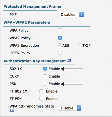
Figure 3-14 Configuring PSK Versus 802.1X
Roaming
In most deployments, multiple access points are deployed, and clients expect to be able to move freely between them without reauthenticating every time. Cisco introduced Cisco Centralized Key Management (CCKM) in pre-802.11i to address the industry needs for roaming. CCKM is most widely implemented in voice over WLAN (VoWLAN) devices. To work across WLCs, WLCs must be in the same mobility group. CCKM is standardized in 802.11r Fast Transition (FT). It is recommended that you have a new unique WLAN that uses FT to keep legacy client support (for example, one SSID for FT clients and one SSID for legacy clients).
802.11r is the IEEE standard for fast roaming. FT introduced a new concept of roaming where the handshake with the new AP is done even before the client roams to the target AP. The initial handshake allows the client and APs to do Pairwise Transient Key (PTK) calculation in advance, thus reducing roaming time. The pre-created PTK keys are applied to the client and AP when the client does the re-association request/response exchange with the new target AP. 802.11r provides two ways of roaming:
![]() Over-the-air: With this type of roaming, the client communicates directly with the target AP using IEEE 802.11 authentication with the FT authentication algorithm.
Over-the-air: With this type of roaming, the client communicates directly with the target AP using IEEE 802.11 authentication with the FT authentication algorithm.
![]() Over-the-DS (distribution system): With this type of roaming, the client communicates with the target AP through the current AP. The communication between the client and the target AP is carried in FT action frames between the client and the current AP and is then sent through the controller.
Over-the-DS (distribution system): With this type of roaming, the client communicates with the target AP through the current AP. The communication between the client and the target AP is carried in FT action frames between the client and the current AP and is then sent through the controller.
Roaming is configured per WLAN in the Fast Transition section, as shown in Figure 3-15.

Figure 3-15 Roaming Configuration with Fast Transition
You also need to use FT 802.1X or FT PSK in the Authentication Key Management section for the Layer 2 security in order for FT to work correctly.
Securing the WLAN
Let’s start to put the pieces together to create a new WLAN following best-practice recommendations for an enterprise SSID built for employees. People often fail to carefully consider the WLAN ID they chose. If you chose an ID greater than 16, the SSID will not belong to the default AP group. AP groups allow you to selectively publish different WLANs to different APs. By default, all access points are put into the default AP group. This means if you want your newly created WLAN to be published to all APs in the default AP group, it needs an ID less than 17.
To create a new WLAN go to WLANs > Create New > Go. Then, as shown in Figure 3-16, select the type (typically WLAN), create a profile name, add an SSID name, and select the ID.
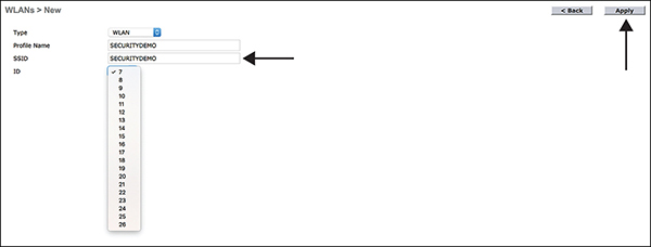
Figure 3-16 New SSID
After clicking Apply to create the new WLAN, the next step is to choose an interface to put the clients on after connection is made to the WLAN. Figure 3-17 illustrates selecting the employee interface.
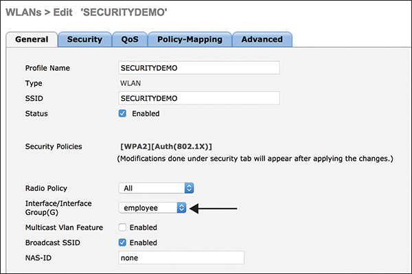
Figure 3-17 Selecting an Interface for a WLAN
When Security is selected, the default settings already have WPA2 with AES for encryption and 802.1X for AKM. These are the recommended options for Layer 2 security. The next step is to reference the correct RADIUS servers on the AAA Servers page, which is shown in Figure 3-18.
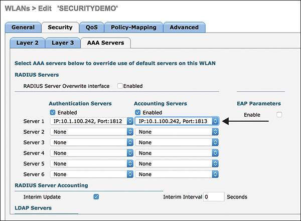
Figure 3-18 Select RADIUS Authentication and Accounting Servers
Note For a detailed explanation of and configuration options for RADIUS, see Integrated Security Technologies and Solutions, Volume II.
The advanced options of the WLAN offer a lot of individual configuration items. Following is a list of the most import ones for securing a WLAN:
![]() Allow AAA Override: Allows the VLAN, QoS, and ACLs to be assigned by the RADIUS server and override the settings on the WLAN. The recommendation is for this setting to be enabled for deployments that integrate with ISE.
Allow AAA Override: Allows the VLAN, QoS, and ACLs to be assigned by the RADIUS server and override the settings on the WLAN. The recommendation is for this setting to be enabled for deployments that integrate with ISE.
![]() Override Interface ACL: This option allows you to override the interface ACL and apply an ACL that is specific to the WLAN. Normally, this feature is not used.
Override Interface ACL: This option allows you to override the interface ACL and apply an ACL that is specific to the WLAN. Normally, this feature is not used.
![]() URL ACL: This option allows you to apply a URL ACL to the WLAN. This allows organizations to develop a blacklist of URLs for the WLAN and apply it before reaching the network.
URL ACL: This option allows you to apply a URL ACL to the WLAN. This allows organizations to develop a blacklist of URLs for the WLAN and apply it before reaching the network.
![]() P2P Blocking Action: Selecting Drop causes the Cisco WLC to discard the P2P packets. This is very useful where you want to isolate all traffic between users on the WLAN. Selecting Forward-UpStream causes the packets to be forwarded on the upstream VLAN. The device above the Cisco WLC decides what action to take regarding the packet. If you have a router with ACLs or a firewall, the external device now can control what types of traffic can be forwarded between clients. For example, you might want to allow Jabber messages and voice but not MS-RPC traffic between wireless users.
P2P Blocking Action: Selecting Drop causes the Cisco WLC to discard the P2P packets. This is very useful where you want to isolate all traffic between users on the WLAN. Selecting Forward-UpStream causes the packets to be forwarded on the upstream VLAN. The device above the Cisco WLC decides what action to take regarding the packet. If you have a router with ACLs or a firewall, the external device now can control what types of traffic can be forwarded between clients. For example, you might want to allow Jabber messages and voice but not MS-RPC traffic between wireless users.
![]() Client Exclusion: This option allows you to enable or disable the timeout for disabled client machines. Client machines are disabled by their MAC address. This option is normally enabled. For more information, review the “Client Exclusion” section, later in this chapter.
Client Exclusion: This option allows you to enable or disable the timeout for disabled client machines. Client machines are disabled by their MAC address. This option is normally enabled. For more information, review the “Client Exclusion” section, later in this chapter.
![]() DHCP Addr. Assignment: This option requires all WLAN clients to obtain IP addresses from the DHCP server. This prevents clients from assigning their own static IP addresses.
DHCP Addr. Assignment: This option requires all WLAN clients to obtain IP addresses from the DHCP server. This prevents clients from assigning their own static IP addresses.
![]() MFP Client Protection: The default, Optional, is normally left selected because MFP on the client requires Cisco Compatible Extensions (CCX) to be supported on the client. For more information, review the “Management Frame Protection” section, later in this chapter.
MFP Client Protection: The default, Optional, is normally left selected because MFP on the client requires Cisco Compatible Extensions (CCX) to be supported on the client. For more information, review the “Management Frame Protection” section, later in this chapter.
![]() NAC State: ISE NAC is the recommended setting for deployments with ISE.
NAC State: ISE NAC is the recommended setting for deployments with ISE.
![]() RADIUS Client Profiling: This allows the WLC to send up RADIUS accounting information about the client for ISE to profile the connected clients. If you are using ISE, this is normally enabled.
RADIUS Client Profiling: This allows the WLC to send up RADIUS accounting information about the client for ISE to profile the connected clients. If you are using ISE, this is normally enabled.
![]() Local Client Profiling: This allows the WLC to learn what type of device is connecting to the WLAN. Normally, you should enable both DHCP and HTTP profiling, regardless of whether or not RADIUS profiling is enabled.
Local Client Profiling: This allows the WLC to learn what type of device is connecting to the WLAN. Normally, you should enable both DHCP and HTTP profiling, regardless of whether or not RADIUS profiling is enabled.
![]() FlexConnect: If you are doing a FlexConnect deployment, you need to review and configure this set of options, which includes everything from local switching and authentication to DHCP processing.
FlexConnect: If you are doing a FlexConnect deployment, you need to review and configure this set of options, which includes everything from local switching and authentication to DHCP processing.
Figure 3-19 illustrates some of these advanced settings.
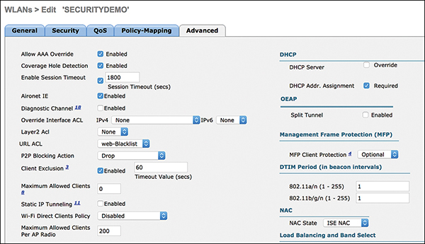
Figure 3-19 Advanced WLAN Settings
Configuring Wireless Protection Policies
Wireless is a medium for communication and is great for productivity, but it introduces challenges that do not exist on wired networks. The simple fact that malicious individuals can see wireless signals from their car in the parking lot opens up wireless to a slew of different threats and risk. In order to address the threats, Cisco and the rest of the industry have added useful features to minimize the risks of wireless deployments. Some of the most desirable features are configured under Security > Wireless Protection Policies. This section reviews these features and the benefits each of them brings.
Rogue AP Detection
Rogue AP detection is all about identifying any device that is sharing your spectrum but is not managed by you. A majority of rogues are set up by insiders, who can run to the store and get an AP inexpensively so that they can have the convenience of controlling their own AP. These users are ignorant of the risks involved with this behavior. A rogue AP becomes dangerous to an organization when it is set up to use the same SSID as your network, when it is detected to be on the wired network, or when it is set up by an outsider, most of the time with malicious intent.
How does any organization deal with the rogue AP threat? By detecting, classifying, and mitigating rogue APs.
Detecting Rogue APs
A WLC can tell APs to listen for non-infrastructure access points, clients, and ad hoc networks. Radio resource management (RRM) scanning is used to detect the presence of rogue devices. RRM can use two types of scanning:
![]() Off-channel scanning: This operation, performed by local mode and FlexConnect (in connected mode) APs, uses a time-slicing technique that allows client service and channel scanning using the same radio. By going off channel for a period of 50 milliseconds every 16 seconds, the AP, by default, spends only a small percentage of its time not serving clients.
Off-channel scanning: This operation, performed by local mode and FlexConnect (in connected mode) APs, uses a time-slicing technique that allows client service and channel scanning using the same radio. By going off channel for a period of 50 milliseconds every 16 seconds, the AP, by default, spends only a small percentage of its time not serving clients.
![]() Monitor mode scanning: This operation, which is performed by monitor mode and adaptive wIPS monitor mode APs, uses 100% of the radio’s time for scanning all channels in each respective frequency band. This allows for greater speed of detection and enables more time to be spent on each individual channel. Monitor mode APs are also far superior at detecting rogue clients as they have a more comprehensive view of the activity occurring in each channel.
Monitor mode scanning: This operation, which is performed by monitor mode and adaptive wIPS monitor mode APs, uses 100% of the radio’s time for scanning all channels in each respective frequency band. This allows for greater speed of detection and enables more time to be spent on each individual channel. Monitor mode APs are also far superior at detecting rogue clients as they have a more comprehensive view of the activity occurring in each channel.
Any AP not broadcasting the same RF group name or part of the same mobility group is considered a rogue.
Another way to detect rogue APs is to use Rogue Location Discovery Protocol (RLDP). Rogue detectors are used to identify whether a rogue device is connected to the wired network. An AP connects to a rogue AP as a client and sends a packet to the controller’s IP address. This works only with open rogue access points. Figure 3-20 shows the options for selecting which APs can use RLDP.
Note If AllAps is selected, the AP removes all client sessions and shuts down its radio prior to performing RLDP. For this reason, most organizations choose to only use monitor mode APs.
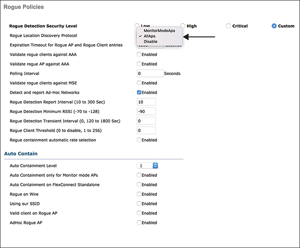
Figure 3-20 RLDP Access Point Selection
An organization can make an AP operate as a rogue detector full time by selecting Rogue Detector as the AP mode and placing it on a trunk port so that it can hear all wired-side connected VLANs. It proceeds to find the clients on the wired subnet on all the VLANs. The rogue detector AP listens for Address Resolution Protocol (ARP) packets in order to determine the Layer 2 addresses of identified rogue clients or rogue APs sent by the controller. If a Layer 2 address that matches is found, the controller generates an alarm that identifies the rogue AP or client as a threat.
Classifying Rogue APs
Classification can be based on threat severity and mitigation action. For example, if a rogue AP has a foreign SSID, is not on your network, is secured, and has a weak RSSI (indicating a distant location), then it probably is a neighboring business’s AP and not something to be concerned about. Classification allows you to customize the rogue rules and should be tailored to the customer risk model.
To create a rogue rule, go to Security > Wireless Protection Policies > Rogue Policies > Rogue Rules > Add Rule. For example, Figures 3-21 and 3-22 illustrate the creation of a rogue rule for a friendly classification for a coffee shop SSID and RSSI minimum of –80 dBm.

Figure 3-21 Adding a New Rogue Rule
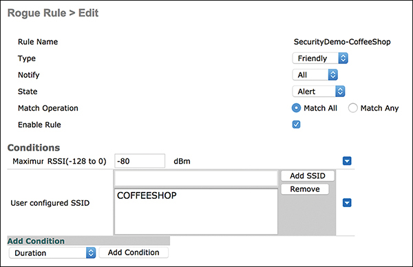
Figure 3-22 Friendly Rogue Rule with SSID and RSSI Criteria
Another popular rule looks for rogue APs that are impersonating your SSID. Figure 3-23 shows a rule that matches a managed SSID (that is, an SSID that is added to the controller) and has a minimum RSSI of –70 dBm.
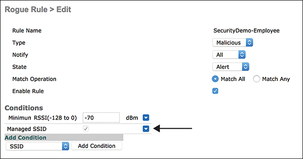
Figure 3-23 Malicious Rogue Rule with Managed SSID and RSSI Criteria
You can manually classify SSIDs as friendly by adding the MAC address of the AP to Security > Wireless Protection Policies > Rogue Policies > Friendly Rogue.
By default, all access points are unclassified unless you create rules, manually set the MAC address to friendly, or manually classify them under Monitor > Rogues > Unclassified Rogue APs. Figure 3-24 shows how an unclassified AP can be manually classified as friendly or malicious.
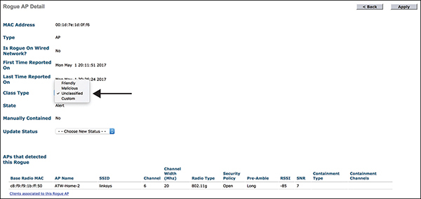
Figure 3-24 Manually Classify a Rogue AP
Mitigating Rogue APs
Mitigation can be done by physically sending someone to find and remove a rogue, manually shutting down switch ports, or implementing wireless containment. A valid AP can contain a rogue AP and clients by sending de-authentication packets to the rogue clients and AP. An organization can employ local, monitor mode, or FlexConnect APs to perform this function, but there can be an impact on client performance on managed APs. Use auto containment to nullify the most alarming threats.
Warning Improperly used containment can have legal consequences, depending on the country and local laws. Pay attention when the WLC presents the warning “Using this feature may have legal consequences. Do you want to continue?”
When configuring containment (in Security > Wireless Protection Policies > Rogue Policies > General), you must set a rogue detection security level to support containment:
![]() Low: Basic rogue detection for small-scale deployments. Auto containment is not supported for this security level.
Low: Basic rogue detection for small-scale deployments. Auto containment is not supported for this security level.
![]() High: Basic rogue detection and auto containment for medium-scale or less-critical deployments. RLDP is disabled for this security level.
High: Basic rogue detection and auto containment for medium-scale or less-critical deployments. RLDP is disabled for this security level.
![]() Critical: Basic rogue detection, auto containment, and RLDP for highly critical deployments.
Critical: Basic rogue detection, auto containment, and RLDP for highly critical deployments.
![]() Custom: Customized rogue policy parameters.
Custom: Customized rogue policy parameters.
The Auto Contain section of the Rogue Policies page gives options on the types of events/rogues that warrant auto containment. The Auto Containment Level setting allows an administrator to configure how many APs will be used for auto containment; if Auto is selected, the ASA dynamically determines the appropriate number of APs to use. Rogue on Wire, Using Our SSID, Valid Client on Rogue AP, and AdHoc Rogue AP are all configurable items for enabling auto containment. Figure 3-25 illustrates a sample configuration that uses monitor mode APs to provide auto containment of some of the event types.
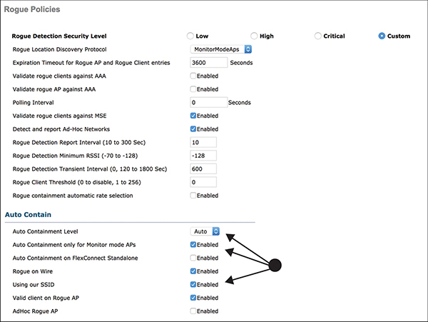
Figure 3-25 General Rogue Policy and Containment Configuration
If a malicious SSID or criterion is known in advance, a rule can be specified to match and contain it, as illustrated in Figure 3-26.

Figure 3-26 Malicious Rogue Rule with SSID Criteria
Also, you can manually contain an AP the same way you would manually classify rogue APs.
Wireless Threat Detection and Mitigation
Most organizations have deployed some type of intrusion detection or prevention on their wired networks, but many of them do not realize that there are threats that focus on 802.11 that otherwise are not visible or available to a wired network IDS/IPS. The next sections describe the capabilities of both wireless IDSs and IPSs in a Cisco Unified Wireless deployment.
Wireless Intrusion Detection Systems
The WLC performs IDS analysis using information obtained from all the connected APs, and it reports detected attacks to WLC. The wireless IDS analysis is complementary to any analysis that can otherwise be performed by a wired network IDS/IPS. The wireless IDS signature files used by the WLC are included in WLC software releases; however, they can be updated independently using a separate signature file. By default, 17 standard signatures come with a WLC.
The list of default signatures is illustrated in Figure 3-27 and can be found by going to Security > Wireless Protection Policies > Standard Signatures.

Figure 3-27 Wireless IDS Signatures
When the ID of a signature is clicked, the details of the signature, including frequency and data pattern to match, are shown. Figure 3-28 shows the NetStumbler generic signature as an example.
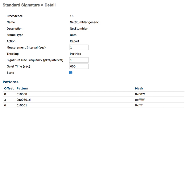
Figure 3-28 NetStumbler Generic Signature Detail
Custom signatures are displayed in the Custom Signatures window. You can configure custom IDS signatures or bit-pattern matching rules to identify various types of attacks in incoming 802.11 packets by uploading them to the controller. You do this at Commands > Download File by selecting Signature File and specifying the transfer method and filename. Example 3-1 shows an example of a signature in text format that could be uploaded as a custom signature.
Example 3-1 Signature in Text Format
Name = "NetStumbler generic", Ver = 0, Preced= 16, FrmType = data, Pattern =
0:0x0108:0x03FF, Pattern = 27:0x00601d:0xFFFFFF, Pattern = 30:0x0001:0xFFFF, Freq  = 1, Quiet = 600, Action = report, Desc="NetStumbler"
To see if an IDS signature is alerting, you can go to Security > Wireless Protection Policies > Signature Events Summary, as shown in Figure 3-29.
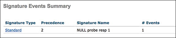
Figure 3-29 Signature Events Summary
Wireless Intrusion Prevention Systems
The one problem with an IDS is that it cannot block traffic; it can only alarm. Enter Cisco’s adaptive Wireless Intrusion Prevention System (wIPS). With extended signature support and protection against more than 100 different threat conditions, wIPS is an important part of any mission-critical wireless deployment. In order to provide wIPS, a WLC must integrate with Cisco’s Mobility Services Engine (MSE) and Cisco’s Prime Infrastructure (PI) solutions. Figure 3-30 illustrates the communication that takes place between the different solutions.

Figure 3-30 Adaptive Wireless Intrusion Prevention System
The following important protocols are needed for the adaptive wIPS architecture to function:
![]() Network Mobility Services Protocol (NMSP): This protocol is used for communication between WLCs and the MSE. In the case of a wIPS deployment, this protocol provides a pathway for alarm information to be aggregated from controllers to the MSE and for wIPS configuration information to be pushed to the controller. This protocol is encrypted.
Network Mobility Services Protocol (NMSP): This protocol is used for communication between WLCs and the MSE. In the case of a wIPS deployment, this protocol provides a pathway for alarm information to be aggregated from controllers to the MSE and for wIPS configuration information to be pushed to the controller. This protocol is encrypted.
![]() Simple Object Access Protocol (SOAP/XML): This protocol provides a method of communication between the MSE and PI. This protocol is used to distribute configuration parameters to the wIPS service running on the MSE.
Simple Object Access Protocol (SOAP/XML): This protocol provides a method of communication between the MSE and PI. This protocol is used to distribute configuration parameters to the wIPS service running on the MSE.
![]() Simple Network Management Protocol (SNMP): This protocol is used to forward wIPS alarm information from the MSE to the PI. It is also utilized to communicate rogue access point information from a WLC to the PI.
Simple Network Management Protocol (SNMP): This protocol is used to forward wIPS alarm information from the MSE to the PI. It is also utilized to communicate rogue access point information from a WLC to the PI.
In order to configure adaptive wIPS, a profile must be configured on PI and pushed to the controllers and MSE. Figure 3-31 shows the details of a wIPS profile on PI.
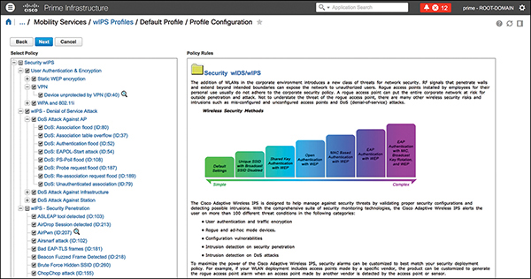
Figure 3-31 Prime Infrastructure wIPS Profile Configuration
An adaptive wIPS solution has several enhancements over the WLC’s wIDS solution. First, it provides additional threat identification and protection:
![]() Customizable severities: Severity of alarms is set based on the security threat level and operation impact on a wireless production network. For example, most DoS attacks may have an operational impact on the wireless infrastructure. Thus, their severity is set to Critical by default.
Customizable severities: Severity of alarms is set based on the security threat level and operation impact on a wireless production network. For example, most DoS attacks may have an operational impact on the wireless infrastructure. Thus, their severity is set to Critical by default.
![]() Capture attack forensics: A toggle-based packet capture facility provides the ability to log and retrieve a set of wireless frames. This feature is enabled on a per-attack basis from within the wIPS profile configuration of PI.
Capture attack forensics: A toggle-based packet capture facility provides the ability to log and retrieve a set of wireless frames. This feature is enabled on a per-attack basis from within the wIPS profile configuration of PI.
![]() Location integration: With MSE location, administrators can easily find an attacker on the floorplan.
Location integration: With MSE location, administrators can easily find an attacker on the floorplan.
![]() Consolidation of alerts: PI can provide a unified view of security alerts from multiple controllers and MSE.
Consolidation of alerts: PI can provide a unified view of security alerts from multiple controllers and MSE.
Access points are responsible for detecting threats with signatures. The following options exist to provide wIPS capabilities for enterprise deployments:
![]() Enhanced local mode (ELM): This mode allows local or FlexConnect APs to run an AP submode of a wIPS and operates effectively for on-channel (the channel the AP is currently servicing clients on) attacks, without any compromise to performance in terms of data, voice, and video clients and services. ELM does scan for off-channel (other channels the AP is not servicing clients on) attacks, but it is considered best effort.
Enhanced local mode (ELM): This mode allows local or FlexConnect APs to run an AP submode of a wIPS and operates effectively for on-channel (the channel the AP is currently servicing clients on) attacks, without any compromise to performance in terms of data, voice, and video clients and services. ELM does scan for off-channel (other channels the AP is not servicing clients on) attacks, but it is considered best effort.
![]() Dedicated monitor mode APs: This allows for 100% channel scanning but requires an organization to deploy an overlay network to passively listen for threats.
Dedicated monitor mode APs: This allows for 100% channel scanning but requires an organization to deploy an overlay network to passively listen for threats.
![]() Wireless Security and Spectrum Intelligence (WSSI) module: For organizations running 3600/3700 series APs, instead of deploying extra APs and creating an overlay network, the WSSI module allows you to install a module into the local/FlexConnect AP, whose sole responsibility is to scan all channels for threats and spectrum intelligence.
Wireless Security and Spectrum Intelligence (WSSI) module: For organizations running 3600/3700 series APs, instead of deploying extra APs and creating an overlay network, the WSSI module allows you to install a module into the local/FlexConnect AP, whose sole responsibility is to scan all channels for threats and spectrum intelligence.
![]() 2800/3800 series access points: These newer APs contain a flexible radio architecture. In a sense, the AP is a tri-band radio as it contains a dedicated 5 GHz radio to serve clients and another flexible radio (known as an XOR radio) that can be assigned the wIPS function within the network.
2800/3800 series access points: These newer APs contain a flexible radio architecture. In a sense, the AP is a tri-band radio as it contains a dedicated 5 GHz radio to serve clients and another flexible radio (known as an XOR radio) that can be assigned the wIPS function within the network.
Non-802.11 Attacks and Interference
While normally not thought of as a security feature, Cisco CleanAir technology is an effective tool for monitoring and managing your network’s RF conditions. The following are some of the threats that can be addressed using CleanAir:
![]() Non-Wi-Fi transmitter or RF jammer detection and location
Non-Wi-Fi transmitter or RF jammer detection and location
![]() Non-Wi-Fi bridge detection and location
Non-Wi-Fi bridge detection and location
![]() Non-Wi-Fi access point detection and location
Non-Wi-Fi access point detection and location
![]() Layer 1 DoS attack location and detection (Bluetooth, microwave, and so on)
Layer 1 DoS attack location and detection (Bluetooth, microwave, and so on)
Client Exclusion
At a basic level, client exclusion is a set of rules that a WLC uses to evaluate whether clients are misbehaving when connecting or while connected to the WLAN. By default, each WLAN automatically excludes for 60 seconds clients that match any of the following rules:
![]() Excessive 802.11 association failures: Clients are excluded on the sixth 802.11 association attempt after five consecutive failures.
Excessive 802.11 association failures: Clients are excluded on the sixth 802.11 association attempt after five consecutive failures.
![]() Excessive 802.11 authentication failures: Clients are excluded on the sixth 802.11 authentication attempt after five consecutive failures.
Excessive 802.11 authentication failures: Clients are excluded on the sixth 802.11 authentication attempt after five consecutive failures.
![]() Excessive 802.11X authentication failures: Clients are excluded on the fourth 802.1X authentication attempt after three consecutive failures.
Excessive 802.11X authentication failures: Clients are excluded on the fourth 802.1X authentication attempt after three consecutive failures.
![]() IP theft or reuse: Clients are excluded if the IP address is already assigned to another device.
IP theft or reuse: Clients are excluded if the IP address is already assigned to another device.
![]() Excessive web authentication failures: Clients are excluded on the fourth web authentication attempt after three consecutive failures.
Excessive web authentication failures: Clients are excluded on the fourth web authentication attempt after three consecutive failures.
Client exclusion can be configured at Security > Wireless Protection Policies > Client Exclusion Policies (see Figure 3-32).

Figure 3-32 Client Exclusion Policies
After the default 60 seconds, clients are able to try to connect again. If the timer is severely increased or a timeout setting of 0 is used, indicating that administrative control is required to reenable the client, then sometimes the users will call the helpdesk to be manually removed from the excluded list. To remove the client from the exclusion list manually, go to Monitor > Clients and click the blue drop-down for the client and then click Remove.
Management Frame Protection
Management frames facilitate connectivity and status but can also be used by malicious users for attacks. One popular attack is a de-authentication attack, where the attacker sends disassociate packets to one or more clients that are currently associated with a particular access point. This allows the attacker to uncover hidden SSIDs, attempt to get the client to connect to a rogue AP, or capture WPA/WPA2 handshakes. The only way to protect against this type of attack is to use management frame protection (MFP).
MFP provides security for the otherwise unprotected and unencrypted 802.11 management messages passed between access points and clients.
The MIC component of MFP ensures that a frame has not been tampered with, and the digital signature component ensures that the MIC could have only been produced by a valid member of the WLAN domain.
Infrastructure MFP
Infrastructure MFP protects management frames by adding the message integrity check information element (MIC-IE) to the frames emitted by APs (and not those emitted by clients), which are then validated by other APs in the network. Infrastructure MFP uses a cryptographically hashed digital signature mechanism to insert the MIC into 802.11 management frames. This allows for identification of legitimate members of a WLAN deployment, as well as rogue infrastructure devices and spoofed frames through their lack of valid MICs. When enabled, infrastructure MFP provides management frame protection, management frame validation, and event reporting. When an AP that is configured to validate MFP frames receives a frame with an invalid MIC, it reports it to the WLC.
Infrastructure MFP is configured under AP Authentication Policy, found at Security > Wireless Protection Policies > AP Authentication (see Figure 3-33).

Figure 3-33 AP Authentication Policy
When you enable the AP authentication feature, the access points sending RRM neighbor packets with different RF network names are reported as rogues.
When you enable infrastructure MFP, it is enabled globally for the Cisco WLC. You can enable or disable infrastructure MFP validation for a particular access point or protection for a particular WLAN if MFP is enabled globally for the Cisco WLC.
Note This setting does not affect client MFP, which is configured per WLAN.
Client MFP
Client MFP shields authenticated clients from spoofed frames, which prevents many of the common attacks against wireless LANs. Cisco client MFP requires a client to have Cisco Compatible Extensions v5 (CCXv5) in order to negotiate a signature process with the AP. CCXv5 allows the clients to learn the mobility group MFP key before they can detect and reject invalid frames.
Client MFP encrypts management frames that are sent between APs and CCXv5 clients so that both the AP and the client can take preventive action by dropping spoofed class 3 management frames (that is, management frames passed between an AP and a client that is authenticated and associated). Client MFP leverages the security mechanism defined by IEEE 802.11i to protect the following types of class 3 unicast management frames: disassociation frames, deauthentication frames, and QoS WMM actions.
Client MFP supplements infrastructure MFP rather than replacing it because infrastructure MFP continues to detect and report invalid unicast frames sent to clients that are not client-MFP capable as well as invalid class 1 and class 2 management frames. Infrastructure MFP is applied only to management frames that are not protected by client MFP. If you require a non-CCXv5 client to associate a WLAN, client MFP should be configured as disabled or optional.
By default, client MFP is optional for a WLAN, but you can set it to Disabled or Required in the WLAN configuration, found at WLAN > SSID Name Edit > Advanced (see Figure 3-34).
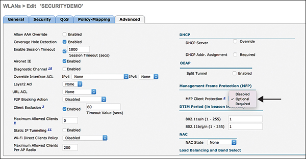
Figure 3-34 Client MFP Configuration
Note Most commercial devices, such as iOS and Android, do not natively support CCXv5. If MFP is required, be aware that some clients may not be allowed to connect.
Protected Management Frames
Cisco Client MFP was used as a basis for IEEE 802.11w Protected Management Frames (PMF) development. 802.11w was ratified in 2009. One of the main drivers for standardizing PMF was to ensure pervasive client support. Today, most operating systems already support 802.11w. Technically, on Cisco controllers, you can enable both PMF and MFP.
The 802.11w protocol applies only to a set of robust management frames that are protected by the PMF service. These include disassociation, deauthentication, and robust action frames. Client protection is achieved by the AP through the addition of cryptographic protection for deauthentication and disassociation frames, thus preventing spoofing of a client in an attack.
PMF configuration is done at WLAN > SSID Name > Edit > Security > Layer 2:
Step 1. Enable PMF by changing PMF from Disabled to Optional or Required (see Figure 3-35).
Step 2. Change the Authentication Key Management setting from PSK or 802.1X to PMF PSK or PMF 802.1X (see Figure 3-36).

Figure 3-35 Enable PMF on the WLAN
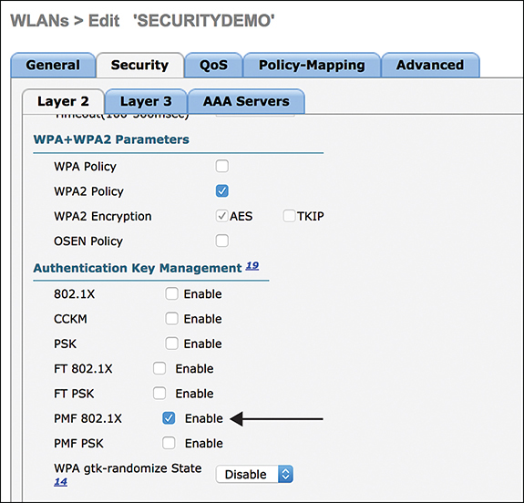
Figure 3-36 Enable PMF on Authentication Key Management
Note Infrastructure MFP cannot be replaced with 802.11w. In infrastructure MFP, the APs sign their beacons and other broadcast management frames. Other APs can detect unsigned broadcast management frames and report rogues to the WLC. This mode does not exist with 802.11w.
Management and Control Plane Protection
The goal of this section is to help with the security interaction between WLCs and APs and the network where they are connected. While not normally a focal point of securing wireless, the management and control plane is an important part of providing a secure wireless solution.
Management Authentication
Authentication can be performed using a local database, RADIUS, or TACACS+ server protected with a username and password. The priority for the different databases is configured at Security > Priority Order > Management User (see Figure 3-37). In cases where multiple databases are configured, an organization can dictate the priority order for the back-end databases.
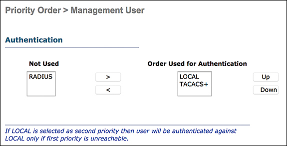
Figure 3-37 Management Authentication Priority
Authentication and authorization services are tied to each other. For example, if authentication is performed using RADIUS or a local database, then authorization is not performed with TACACS+. Rather, authorization would use the permissions associated for the user in the local or RADIUS database, such as read-only or read/write, whereas when authentication is performed with TACACS+, authorization is tied to TACACS+.
To add a new RADIUS authentication server, go to Security > AAA > RADIUS > Authentication > New and add the IP address and shared secret and ensure that Management is checked. If the server will be used only for management authentication, ensure that the Network User check box is not selected.
To add a new TACACS+ authentication server, go to Security > AAA > TACACS > Authentication > New and add the IP address and shared secret. Figure 3-38 illustrates a new TACACS+ authentication server being added in a WLC.
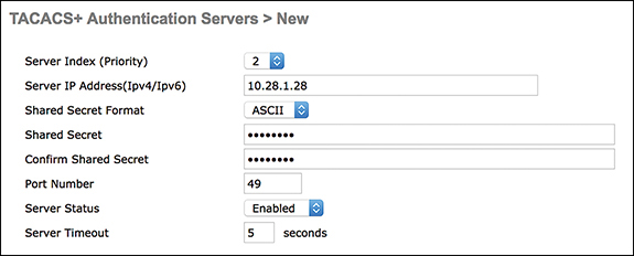
Figure 3-38 New TACACS+ Authentication Server
Authorization that is specific to TACACS+ deployment is task-based rather than per- command-based. The tasks are mapped to various tabs that correspond to the seven menu bar items that are currently on the web GUI:
![]() Monitor
Monitor
![]() WLANs
WLANs
![]() Controller
Controller
![]() Wireless
Wireless
![]() Security
Security
![]() Management
Management
![]() Command
Command
This mapping is based on the fact that most customers use the web interface rather than the CLI to configure a controller. An additional role for lobby admin management is available for those who need to have lobby admin privileges only. In order for basic management authentication via TACACS+ to succeed, you must configure authentication and authorization servers on the WLC. Accounting configuration is optional. Figure 3-39 illustrates adding a new TACACS+ authorization server in the WLC. The IP address and shared secret must match the authentication server information.
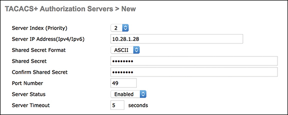
Figure 3-39 New TACACS+ Authorization Server
Accounting occurs whenever a particular user-initiated action is performed successfully. The attributes changed are logged in the TACACS+ accounting server, along with the user ID, the remote host where the user is logged in, date and time, authorization level, and what action was performed and the values provided.
To add a new RADIUS accounting server, go to Security > AAA > RADIUS > Accounting > New and add the IP address and shared secret (the same as the authentication shared secret); also, if the server will only be used for management authentication, ensure that the Network User check box is not selected.
To add a new TACACS+ accounting server, go to Security > AAA > TACACS > Accounting > New and add the IP address and shared secret. Figure 3-40 illustrates adding a new TACACS accounting server in the WLC.
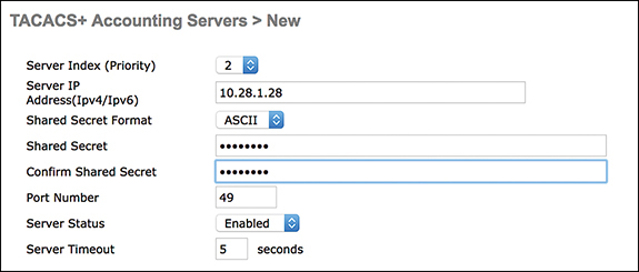
Figure 3-40 New TACACS+ Accounting Server
Note Detailed configuration information of the RADIUS and TACACS servers is provided in Integrated Security Technologies and Solutions, Volume II.
Management Protocols and Access
After enabling external authentication for the WLC, it is important to lock down the management protocols that are allowed on the WLC.
Figure 3-41 shows how HTTP can and should be disabled on the Management > HTTP-HTTPS page.
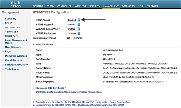
Figure 3-41 HTTP-HTTPS Configuration
Telnet is another protocol that is risky to use for management access. Figure 3-42 shows how Telnet can and should be disabled on the Management > Telnet-SSH page.
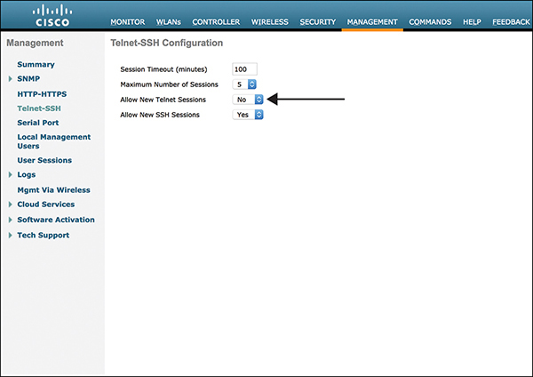
Figure 3-42 Telnet-SSH Configuration
The management over wireless feature allows you to monitor and configure local controllers using a wireless client. In most cases, wireless users should not be allowed to log in to the WLC. To disable management over wireless, go to Management > Management Via Wireless page and uncheck the box, as shown in Figure 3-43.
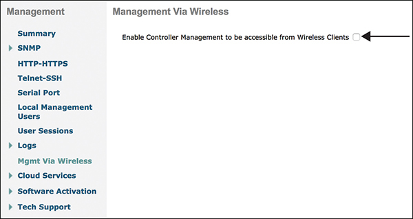
Figure 3-43 Management Via Wireless
CPU ACLs
A CPU ACL controls requests from specific networks/clients to the controller directly. A CPU ACL actually filters traffic that is destined to one of the WLC IP addresses, meaning it is applied on all interfaces but does not filter all types of traffic—only traffic that is destined to the WLC itself.
Tip It is very easy to block yourself from accessing the WLC if you are not careful. If you lock yourself out, log in via the console and remove the ACL that is applied to the controller CPU and then enter the config acl cpu none command. To see if the ACL is applied to the controller CPU, enter the show acl cpu command.
The safest way to create a CPU ACL is to explicitly deny traffic and/or networks that are not supposed to communicate with the WLC and explicitly allow all other traffic. The following is a logical example (not a real configuration example):
deny tcp [CLIENT NETWORKS] [WLC mgmt IP] eq 443
deny tcp [CLIENT NETWORKS] [WLC mgmt IP] eq 22
permit ip any any
To apply the created ACL for IPv4 or IPv6, go to Security > Access Control Lists > CPU Access Control Lists, select Enable CUP ACL, and select the ACL to apply. Figure 3-44 illustrates setting an IPv4 ACL.
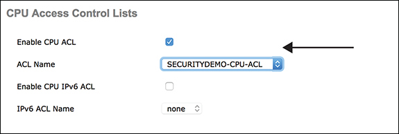
Figure 3-44 CPU ACL
Access Point Protection
The same best practices for securing the WLC apply to APs as well.
By going to Wireless > Access Points > Global Configuration, you can configure the following to help secure the APs (see Figure 3-45):
![]() Login credentials: You can set the username and password to log in directly to an AP through Telnet or SSH.
Login credentials: You can set the username and password to log in directly to an AP through Telnet or SSH.
![]() 802.1X supplicant credentials: You can set the username and password the AP will use to perform EAP-FAST 802.1X login on the wired interface.
802.1X supplicant credentials: You can set the username and password the AP will use to perform EAP-FAST 802.1X login on the wired interface.
![]() Global Telnet SSH: You can turn on/off Telnet and SSH login directly to the AP.
Global Telnet SSH: You can turn on/off Telnet and SSH login directly to the AP.

Figure 3-45 Access Point Global Configuration
Integrating a WLC with Other Security Solutions
A WLC, along with its inherent protections like wIDS and rogue detection, also integrates with other solutions to provide additional security coverage, the primary goal being to secure all connections and the users of wireless.
WLC and ISE
Identity Services Engine (ISE), described in detail in Integrated Security Technologies and Solutions, Volume II, can be used as a RADIUS or TACACS authentication source with a WLC. This enables both 802.1X authentication and guest access through Central Web Authentication (CWA). The WLC can also use Cisco TrustSec to allow for segmentation and integration with other security enforcement points in the network. Starting in the WLC 8.4 release, TrustSec native tagging and Security Group Access Control Lists (SGACL) are supported. This means the WLC or an AP could be used to tag wireless clients’ network traffic with an SGT when bridging from wireless to wired. Instead of using an upstream switch/router for enforcement, the wireless traffic can be enforced directly on the WLC or APs. The WLC or AP can also download an SGACL from ISE. In order to configure TrustSec support, the RADIUS servers must be configured with PAC provisioning, and you must go to Security > TrustSec > General to enable CTS and configure the device ID and password. After configuration, TrustSec environment data is downloaded from ISE, and the security group name table is downloaded onto the WLC.
The WLC can also use SGT Exchange Protocol (SXP) to propagate the security group tags (SGTs) assigned to users across network devices that do not have hardware support for Cisco TrustSec. The SXP sends SGT information to the TrustSec-enabled devices or ISE so devices have the appropriate IP-to-SGT mappings. The WLC can send mappings for IPv4 and IPv6 clients. From WLC release 8.3, the SXP on the Cisco WLC is supported for both centrally and locally switched networks. Also, IP-to-SGT mapping can be done on the WLANs for clients that are not authenticated by Cisco ISE. The Cisco WLC is always in SXP Speaker mode, meaning it sends the mappings. SXP can be configured under Security > TrustSec > SXP Config. For locally switched WLANs in local or FlexConnect mode APs, SXP can be configured by going to Wireless > Access Points > All APs > Trusted Security.
WLC and Stealthwatch
The WLC uses NetFlow to integrate with Cisco Stealthwatch. NetFlow is a record that contains the important details about network transactions: information about when the conversation occurred, the duration of the session, and what ports and protocols were used. Stealthwatch can provide visibility of traffic across the wireless network. Its flow-based analytics can see stealthy attacks, such as data exfiltration, data hoarding, and reconnaissance attacks. Stealthwatch allows your existing network to be used as a security sensor and enforcer to dramatically improve threat defense.
WLC release 8.2 introduced the enhanced NetFlow records exporter. NetFlow v9 sends 17 different data records, as defined in RFC 3954, to external third-party NetFlow collectors such as Stealthwatch.
To configure NetFlow, go to Wireless > NetFlow and create an exporter and a monitor. Then under WLAN > Edit > QoS, select the NetFlow monitor.
Figure 3-46 illustrates how the WLC can send NetFlow to Stealthwatch and Stealthwatch can use ISE to quarantine wireless users.
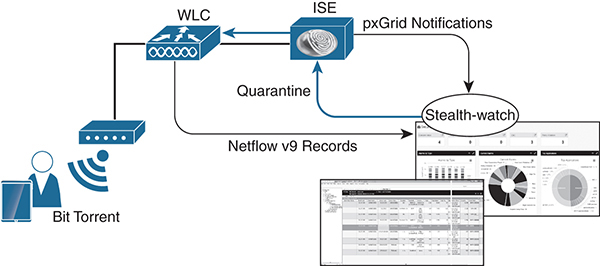
Figure 3-46 Integration with ISE and Stealthwatch
WLC and Umbrella
One security integration that was added in WLC version 8.4 is integration with Cisco Umbrella, formerly known as OpenDNS Umbrella. This integration provides administrators a seamless way to redirect DNS requests to Umbrella. A DNS request always precedes a web request. A WLC intercepts wireless users’ DNS requests from the client and redirects the query to Umbrella servers in the cloud (208.67.222.222, 208.67.220.220). Umbrella servers resolve the DNS query and enforce preconfigured security filtering rules on a per-identity basis to mark the domain as either malicious (and return a blocked page to the client) or safe (and return the resolved IP address to the client). In order to set up the integration, an administrator must obtain an API token for device registration from the Umbrella dashboard and apply the token on the WLC under Security > OpenDNS > General. This registers the device to the OpenDNS account. After registration, profiles should be added to the same page. These profiles then show up in the Umbrella console for customized policies. There are two deployment options on the WLC to redirect wireless clients to Umbrella with the appropriate profile mapping:
![]() Local policies: Allows administrators to customize Umbrella policies based on user roles. In essence, a user is assigned a role via RADIUS authentication from ISE, and a local policy configuration can map that role to an Umbrella profile on the WLC. This allows administrators to customize policies for different user roles in their organization; for example, employees, contractors, and guests can all have different policies.
Local policies: Allows administrators to customize Umbrella policies based on user roles. In essence, a user is assigned a role via RADIUS authentication from ISE, and a local policy configuration can map that role to an Umbrella profile on the WLC. This allows administrators to customize policies for different user roles in their organization; for example, employees, contractors, and guests can all have different policies.
![]() Per WLAN/AP group: Administrators can statically map an entire WLAN or AP group to an Umbrella profile.
Per WLAN/AP group: Administrators can statically map an entire WLAN or AP group to an Umbrella profile.
Along with the profile mappings, there are three Umbrella modes that can be used, depending on the deployment:
![]() Force mode: This mode, enabled by default, is enforced per WLAN and forces all DNS traffic to query Umbrella.
Force mode: This mode, enabled by default, is enforced per WLAN and forces all DNS traffic to query Umbrella.
![]() Ignore mode: WLC honors the DNS server used by the client; it could be an Umbrella server or an enterprise/external DNS server.
Ignore mode: WLC honors the DNS server used by the client; it could be an Umbrella server or an enterprise/external DNS server.
![]() Copy mode: All Internet-bound DNS traffic is forwarded to an Umbrella cloud without any policy options (no blocking/redirection).
Copy mode: All Internet-bound DNS traffic is forwarded to an Umbrella cloud without any policy options (no blocking/redirection).
For detailed information on Umbrella, see Chapter 9.
Summary
In this chapter, you learned about deploying and securing a Cisco Unified Wireless deployment with a wireless LAN controller and access points. You examined the 802.11 standards and how they are applied in the solution and how each of them provides additional security. You found out all the ways to identify threats and risk by deploying wireless and the solutions to minimize or mitigate them.
References
“IEEE 802.11”, https://en.wikipedia.org/wiki/IEEE_802.11
“Wireless TrustSec Deployment Guide,” https://www.cisco.com/c/en/us/td/docs/wireless/controller/technotes/8-4/b_wireless_trustsec_deployment_guide.pdf
“Cisco Umbrella WLAN Integration Guide”, https://www.cisco.com/c/en/us/td/docs/wireless/controller/technotes/8-4/b_cisco_umbrella_wlan_integration_guide.html