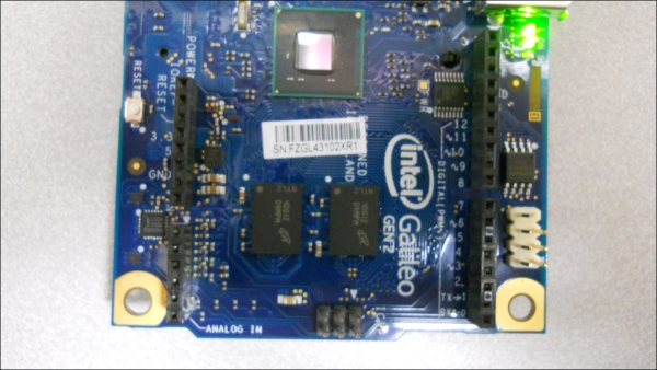
|
AREF
|
This pin provides a reference voltage for the analog inputs. The values on the analog pins will be reported in reference to this voltage. You'll also use this in some applications to provide a reference voltage for sensing devices. You can also provide an external reference value to this pin, which means that the numerical values of the inputs will be scaled according to the value supplied on this pin.
|
|
GND
|
This pin provides a ground reference for the AREF pin.
|
|
Digital (PWM~) 13/2
|
These 11 pins can be used to either read or write digital values. If input, the value will be read as either a 0 or 1 based on the voltage level at the input. If output, the value will be set to either a 0 or 1 based on the logic voltage level (the actual voltage will depend on the voltage logic level of your Arduino. Some are 5V logic level, others are 3.3 V logic level).
|
|
Digital TX->1
|
This pin, and the RX pin next to it, provide a serial interface that can be used to communicate with other devices.
|
|
Digital RX->0
|
This pin, and the TX pin next to it, provide a serial interface that can be used to communicate with other devices.
|
|
Analog IN A5/A0
|
These pins do double duty. Normally, they are used as A/D inputs to the Galileo to read continuous voltage values and turn them into integer values. However, they can also be used as Digital I/O, very similar to the Digital I/O pins.
|
|
Power Vin
|
You can power the Galileo from this pin. This can be especially useful after you have uploaded your program. You can then disconnect the USB port and, when you apply voltage to this pin, your Galileo will boot and run the uploaded program. For the Gen1 board, this needs to be 5 volts. For the Gen2 board, you can use a voltage value from 7 to 12 Volts, so a wide variety of DC power adapter or battery configurations can be used.
|
|
Power GND
|
This pin would give the ground connection associated with the Power Vin connection.
|
|
Power GND
|
This is a ground normally associated with the Power 5V and Power 3.3V outputs.
|
|
Power 5V
|
This is a voltage output set to 5 Volts.
|
|
Power 3.3V
|
This is a voltage output set to 3.3 Volts.
|
|
RESET
|
This pin will reset the processor, which will cause the program to run from the beginning.
|
|
IOREF
|
This provides either a 3.3V, or 5 V reference, indicating the logic level of the board.
|

