
To create the code for this example, start the Galileo IDE. Recall the Blink example you accessed in Chapter 1, Getting Started with the Galileo. The IDE should look like this:
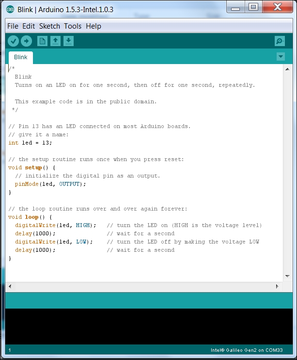
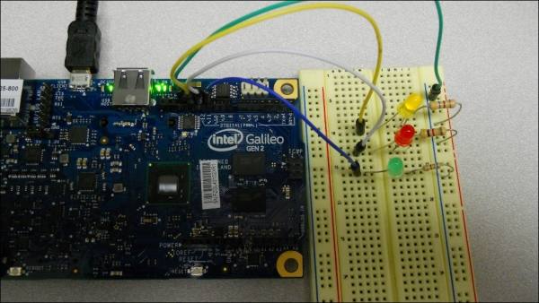
If you remember this code, int led = 13 lit the orange LED on the board. It turns out that LED output pin 13 is also the connection to the 13 pin on the Galileo connector. If you upload and run this program, the LED connected to pin 13 should flash at the same rate as the LED on the Galileo. Here is a picture:
You'll need to add a similar bit of code to get the LEDs connected to pin 12 and 11. Add the following to the sketch on the IDE:

Here, you are replicating the code but connecting the LED connected to pin 13 to the variable led, the LED connected to pin 12 to the variable led1, and the LED connected to pin 13 to the variable led3. You then program them all to be output pins and then in the main loop toggle between high and low. Notice I have two pins toggling together (pins 13 and 11) with the other (pin 12) toggling in the exact opposite sequence. The outer two LEDs should light for one second, then the inner LED should light.
If one or more of the LEDs don't light, check to make sure they are pushed firmly down into the board. You can also change the direction of the LED; perhaps you have the leads in the wrong direction on the board.