
6
IoT-Assisted Smart Device for Blind People
Roshani Raut1, Anuja Jadhav1*, Swati Jaiswal1 and Pranav Pathak2
1Pimpri Chinchwad College of Engineering Pune, Maharashtra, India
2MIT School of Bioengineering Sciences & Research Pune, Maharashtra, India
Abstract
Those who are blind have a lot of trouble going through their daily lives. A lot of effort has gone into making it easier for blind people to complete tasks on their own rather than relying on others. With this inspiration in mind, we proposed and created an intelligent blind stick. The smart walking stick assists visually impaired people in identifying obstacles and getting to their destination. There are a variety of walking sticks and devices that assist users in moving around both indoor and outdoor environments, but none of them include run-time autonomous navigation, object detection and identification warnings, or face and voice recognition. The stick uses IoT, echolocation, image processing, artificial intelligence, and navigation system technology to identify close and far obstacles for the user. If the blind person falls or has some other problem, then the system will send a warning to the designated person. The system uses voice recognition to recognise loved ones.
Keywords: Image processing, input/output and data communication (hardware), sensors (artificial intelligence), artificial intelligence, natural language, voice (input/output device)
6.1 Introduction
Artificial intelligence (AI) has made remarkable strides in bridging the difference between human and machine capabilities. Researchers and enthusiasts alike work on different aspects of the field to produce incredible results. The aim of this field is to allow machines to see the world in the same way as humans do, to see it in similar ways, and to use this knowledge for various tasks such as image and video recognition, image analysis and classification, media recreation, recommendation systems, and natural language processing (NLP). More than one basic calculation—a convolutional neural network (CNN)— has been developed and culminated over time in computer vision with deep learning [1].
The gift of sight is one of nature’s most valuable gifts. Friends who are blind have a lot of trouble going through their daily lives. A lot of effort has gone into making it easier for blind people to complete tasks on their own rather than relying on others. With this inspiration in mind, a variety of inventions for visually impaired people are being created.
6.1.1 A Convolutional Neural Network
CNN is a form of neural network that employs CNNs. CNN is a television network that classifies videos. Using pretrayed CNN, the features from the input image would be extracted, and a feature vector would be created. CNN is used in the image-based model [2].
CNNs, also known as ConvNets, were first proposed by Yann LeCun, a postdoctoral computer science researcher, in the 1980s. LeCun had built on the work of Kunihiko Fukushima, a Japanese researcher who had developed the neocognitron, a fundamental image recognition neural network, only a few years before.
The first CNNs, known as LeNet (after LeCun), were capable of perceiving manually written digits. CNNs discovered a niche market reading postal codes on envelopes and digits on checks in finance and postal administrations and banking.
CNNs are similar to normal meural metworks, since they consist of weight and biassed neurons. Each neuron receives a few data sources, performs a dot product, and alternates with non-linearity. From raw image pixels on one side to class scores on the other, the entire company communicates a single differentiable score feature. They have a loss function on the last layer, which is the completely connected layer, and all of the tricks we developed for learning regular neural networks apply here as well [2].
In any case, despite their ingenuity, ConvNets remained on the periphery of computer vision and AI because they faced a difficult problem: they could not scale. CNNs required a lot of knowledge and resources to produce large-scale images effectively. The technique was only applicable to low-resolution photos at the time.
AlexNet demonstrated in 2012 that the time had come to return to deep learning, the branch of AI that employs complex neural networks. The availability of massive amounts of data, specifically the ImageNet dataset with a large number of marked images, as well as massive computer resources enabled scientists to create complex CNNs that could perform previously impossible computer vision tasks. Convolutional network architectures assume categorically that the information sources are images, allowing us to encode specific properties into the architecture. At that point, the forward work becomes more efficient to perform, and the number of parameters in the network is drastically reduced.
A CNN is a form of neural network that uses con (CNN).
A CNN is a deep learning algorithm that can take in an image as input, assign weights and biases to different objects in the image and then separate them. As compared to other classification algorithms, the amount of image pre-processing needed by a CNN is significantly less. Although primitive techniques require hand-designing channels, CNN can learn these channels/qualities with enough preparation.
The interaction of the visual cortex enlivened the engineering of a CNN, which is almost identical to the connectivity patterns of neurons in the human brain. Single neurons respond to changes in a small area of the visual field called the receptive field. A set of such fields may be used to cover the entire visual area by overlapping them.
For example, a large image, such as 400 × 400 × 3, will activate neurons with weights of 400 * 400 * 3 = 480,000. Furthermore, we would almost certainly need a few of these neurons, so the parameters will quickly add up! The network as a whole is unreliable, and the large number of parameters will lead to overfitting. CNN can be used to solve those problems.
6.1.2 CNN’s Operation
CNNs are made up of several layers of artificial neurons that work together to achieve the best possible results. Artificial neurons are mathematical functions that measure the weighted number of multiple input/output activation functions and are a rough imitation of their biological counterparts [3]. The structure of artficial neuron is shown in Figure 6.1.
The question of how image recognition/deep learning recognizes artifacts in an image arises.
It functions the same way for CNNs. CNN has several layers, which allows for more accurate image classification. CNN is a feed forward network that is commonly used to analyse visible images using a grid-like topology to process data. Any CNN starts with a convolution operation. Figure 6.2 represents the structure of CNN.
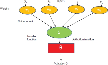
Figure 6.1 Structure of artificial neuron.

Figure 6.2 Convolution neural network.
The layers of CNN are as follows:
- 1. Input layer: The input layer accepts image pixels in the form of arrays as input.
- 2. Hidden layer: This layer performs feature extraction by circulating and manipulating data. To detect patterns in the image, this layer employs a matrix filter and a convolution operation.
Convolutional means to call or twist data around it and change it in order to identify new patterns. A convolutional layer is made up of many filters that perform convolution.
Take a look at the 5 × 5 image below, which only has pixel values of 0 and 1. Sliding the filter matrix over the image and computing the dot product to detect patterns, as shown in Figure 6.3.
The complete form of a rectified linear unit is a ReLU layer, and it essentially deals with the activation function used in CNN. After the function maps have been removed, they must be moved to a ReLU layer. For locating features, real images can have multiple convolutions and ReLU layers [3]. Figure 6.3 shows gives the various types of layers of CNN.
We do not just have one ReLU coming in, but we go through multiple feature extractions and generate multiple ReLU layers for locating the features in ReLU. We have a collection of items, such as multiple features and multiple values that will lead us to the next level.
ReLU’s features include the following:
- i. Makes all negative pixels 0 pixels.
- ii. It also conducts element-by-element operations.
- iii. Causes the network to become non-linear.
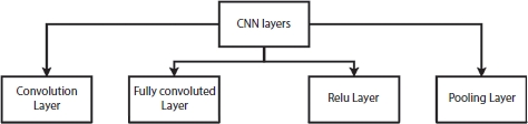
Figure 6.3 Layers of CNN.
- a) Pooling layer: Detects edges, corners, leaves, stems, and other objects using several filters. The term “pooling” refers to the gathering of data. The features that have been corrected are now sent to a pooling layer. Pooling is a downsampling procedure that decreases the function map’s dimensionality [4].
- b) Different filters were used by the pooling layer to classify different parts of the image, such as edges, corners, leaves, stems, and roots [4].
Flattening: Flattening is a method of transforming all resulting two-dimensional arrays from pooled feature maps into one long linear vector.
Finally, a fully linked layer defines the image object. The fully linked layer uses flattened metrics from the pooling layer to identify the picture.
The image’s features are extracted using a mixture of convolutional, ReLU, and pooling layers.
6.1.3 Recurrent Neural Network
A recurrent neural network (RNN) is a type of neural network that is used in machine learning. RNNs are a form of network widely used in text processing. The LSTM (Long Short-Term Memory) model will be used by the RNN for our Language-based model.
We predefine our mark and goal text before training the LSTM model.
6.1.4 Text-to-Speech Conversion
Speech synthesis is the imitation of human speech. It is the process of converting coded text into expression. The module’s input is in text format, and the output is in the form of a human voice.
6.1.5 Long Short-Term Memory Network
LSTM networks are a form of repetitive neural network that can be used in sequence prediction models to learn order dependence. This is an ability that is needed in a variety of fields, including speech recognition and machine learning. Deep learning with LSTMs is a complicated area. The definition of LSTMs and how terms like bidirectional and sequence-to-sequence apply to the field can be difficult to understand. The success of LSTMs is due to their ability to transcend the failures and promises of RNNs [5]. Standard RNNs can now ignore time lags greater than 5 to 10 discrete time steps between specific input and target signals while learning. The problem raises doubts about whether standard RNNs will truly outperform window-based feedforward networks in terms of practical benefits. This problem has no effect on a modern model called “Long Short-Term Memory”. By introducing consistent mistake movement through “constant error carrousels” (CECs) within special units called cells, LSTM can find out how to bind trivial delays over 1,000 discrete time steps. The LSTM solves two common network training problems: vanishing gradient and exploding gradient. The control flow of an LSTM is similar to that of an RNN. It processes data as it travels across the network. The activities within the distinctions are the cells of the LSTM. These activities help the LSTM remember or forget information [5]. The basic concept of LSTMs is the cell state and its numerous gates. The cell state served as a highway, transporting relative information across the sequence chain. It is the network’s “memory”, if you will. The cell state can convey critical data during the processing chain. As a result, data from earlier time steps can be progressed to later time steps, minimizing the short memory impact. As data passes through gates, it is added to or removed from the cell state. The gates are numerous neural organizations that determine which cell state data is allowed. The gates will decide which data to keep and which to delete throughout the planning process.
The sigmoid function in gates is similar to the tanh function. This is useful for updating or forgetting details since any number increased by 0 would be 0, causing esteems to disappear or be “neglected”. Since any number multiplied by one equals one, the number remains the same or is “kept”. The network will determine which information is unimportant and therefore can be ignored, as well as which information should be kept. Figure 6.4 represents the structure of LSTM.
The following are examples of LSTM gates:

Figure 6.4 LSTM structure.
- 1) Input gate: The input gate is used to refresh the cell state. To begin, we use a sigmoid capacity to transfer the hidden state and current input state. By adjusting the qualities to be anywhere between 0 and 1, this determines which values are important to change. Similarly, transfer the secret state and current state to the tanh function to help guide the network by crushing values between -1 and 1 [6]. Use the sigmoid function to multiply the tanh function. The sigmoid function will then decide the data from the tanh function is necessary to hold.
- 2) Forget gate: This gate determines whether data should be discarded or saved. The sigmoid ability passes data from the previous secret state as well as data from the current information. Qualities are rated between 0 and 1 on a scale of 1 to 10. The more like 0 intends to ignore and the more like 1 intends to hold, the better.
- 3) Cell state: The cell state is multiplied by the forget vector pointwise first. If this is duplicated by values close to 0, then the cell state’s qualities which deteriorate. The output of the input gate is then used to perform a pointwise addition on the cell state, updating it to new qualities that the neural network considers essential. As a result, a new cell state has emerged.
- 4) Output gate: The output gate specifies the hidden state that will be revealed next. Keep in mind that the hidden state saves data from previous inputs. The hidden condition is often used to make predictions. Second, we switch the previous hidden state and the current input using a sigmoid ability. The tanh work receives the newly changed cell state. We replicate the tanh output with the sigmoid output to determine what data the hidden state can convey. The output is the hidden state.
CNN and LSTM are two types of machine learning algorithms.
CNN LSTMs were developed to solve visual time sequence prediction problems and to generate text explanations from video/image sequences. The following sections go through the problems with action identification, image and video descriptions in particular:
- • Activity Recognition: Creating a textual summary of a movement in a series of photographs.
- • Video Description: Creating a text-based representation of a series of images
- • Image Description: Creating a textual representation of a single image [7].
“CNN LSTMs are a type of model that is both spatially and temporally deep and can be applied to a wide range of vision tasks involving sequential inputs and outputs.”
This style is used to create textual explanations of photographs. It is important to use a CNN that has been pre-trained on a difficult image classification task before being repurposed as a feature extractor to solve the subtitle generation problems. A CNN is commonly used as an image “encoder” by pre-training it for an image classification task and then contributing the final hidden layer to the RNN decoder that generates sentences. CNN-LSTM can be used to derive features from LSTM audio and textual input data for speech recognition and NLP issues [8].
This architecture is appropriate for issues such as follows:
- • Input that has spatial construction, such as a 2D design of pixels in an image or a 1D design of words in a phrase, pieces, or documents.
- • Involve the production of output with temporal construction, such as words in a textual depiction, or have a temporal construction in their input, such as requests for images in a video or words in text [9].
6.2 Literature Survey
Blindness is described as a state of sightlessness in which both eyes have completely lost their vision. Diabetes, macular degeneration, physical injury, infection, and glaucoma are the most common causes of impairment [10].
There are 39 million people who are blind, and another 246 million who have poor vision. The number of people who have lost their eyesight is rapidly rising. According to the Royal National Institute of Blind People (RNIB), the number of visually disabled people in the United Kingdom will exceed 2 million by 2020 [11].
The distance between the stick and the points in front of it is calculated using an ultrasonic sensor [12]. The infrared sensor is used to detect the amount. It works by reflecting an infrared beam to determine the distance to the target [13]. The image sensor’s job is to detect certain obstacles with pinpoint accuracy. The image sensor is used to capture and send images to the microcontroller at regular intervals. The task at hand is to compare the captured image to the database and determine the appropriate output. Face detection and recognition, as well as street sign recognition, can be done with image processing [14]. Raspberry Pi is a single-board computer that is small and powerful. It connects to a computer, keyboard, mouse, and other peripherals. It has a fantastic learning and programming environment, as well as being used to communicate with hardware components [15]. The most available route is found using a GPS system. If he is in an emergency, then the SMS system is also used to send messages to his friends and family [16]. The Bluetooth module is used to transmit signals to the user through the module-connected cell phone [17]. Stick is only used to make smart choices, show them the right direction, and keep them away from obstacles [18]. The object’s distance is measured using TOF (time of flight), the location and angle of sensors on the stick, the threshold limit of distances using ultrasonic sensors, and appropriate algorithms [19].
6.3 Smart Stick for Blind People
People who are blind tend to stick together: There are currently a large number of visually disabled people all over the world. Individuals with low site seeing to full vision loss are included in this group. They believe it is extremely difficult to cross the street or arrive at their specific destination with the help of another human. There are 50 million people in the United States who are visually impaired and are of working age. They need independent mobility to work or walk outside, as well as to be important for the norm and to complete any remaining basic tasks. According to 2011 census results, India has 12 million people with visual impairment, the largest number of any country on the planet.
The traditional stick is incapable of distinguishing between impediments in front of you and potholes in the road. It is no longer in use. As a result, it is essential to upgrade it with current technology. With today’s technology, such as the IoT and AI, it is possible to make the lives of blind people much easier and safer. Figure 6.5 gives the block diagram of hardware structure of smart stick.
The use of a white cane has considerable drawbacks because the subject must be in close proximity to the deterrent and use the tip of the white cane to feel the area of the deterrent. When using the white cane to detect obstacles, he can be struck by various obstacles. The white cane provides no detail about the nearby barrier.
The smart stick is equipped with a variety of sensors that will alert the user to various impediments that may appear in his path while walking. Clients can check their pulse rate and body temperature with this smart stick’s health monitoring features. GPS and GSM modules are preprogrammed in order to monitor the user’s position and transmit a warning message to another individual. The voice warning system is another important feature of this smart stick.

Figure 6.5 Block diagram of hardware structure of smart stick.
Deterrent, pit, wet floor, and medical issues will be communicated to the client through voice warning. This will increase the versatility of a visually disabled person because he will become more aware as a result of hearing voice alarms. Item recognition, pit detection, and water detection are some of the other notable features of this smart stick. These smart sticks are helpful in managing the mobility of elderly and visually disabled clients, as well as avoiding mishaps. This stick has a number of interconnected subsystems. Power, microcontroller, ultrasonic sensor, PIR sensor, electrodes, pulse rate sensor, temperature, speaker, and LCD are all built into the handle.
Directions in a route to follow are recommended based on this experience. The intelligent blind stick simplifies and protects the lives of blind friends. The AI-powered visually impaired stick is a novel tool designed to assist outwardly handicapped people in finding better routes and making wise decisions on which direction to follow that is free of obstacles before they cross a certain distance. Our quest space includes using three ultrasonic sensors from the front, left, and right to find the best way for a visually impaired partner who does not have an obstacle within a certain distance. These sensors detect obstacles using ultrasonic waves and direct visually impaired people to the bearing that is free of checks within a certain range. The information is gathered using three sensors that detect the distance between the obstacle and the user.
This sensor input is organized and transmitted to a blind person through an audio facility, which is then used to make a decision on which route to take that is free of obstacles. A blind man trying to cross a street was seen by George Bonham in 1930. The man wields a black stick that the motorist does not see. To prevent such occurrences, George decided to paint the stick red and white to make it more visible on the lane. Aluminum Folding Cane: This cane is inexpensive, compact, and portable. Allows blind people to use their homes more conveniently and take up less room. It can be seen at night because of the red and white colors.
Man-machine communication based on commands or text can be implemented using speech or voice recognition technologies. It is an important technology in the majority of human-machine interfaces. It is also possible to use pattern matching technology. AI plays a significant role in decision-making [10].
6.3.1 Hardware Requirements
6.3.1.1 Ultrasonic Sensor
Ultrasound waves are waves that can be heard by the human ear. They have a frequency of over 20 kHz. Ultrasonic sensors, similar to SONAR or RADAR, are used to locate objects or obstacles using these waves. The sound of waves, according to Laplace, is 343 m/s. Transducers transform electrical energy into mechanical energy in order to produce ultrasonic vibrations. The “Pulse Reflection Procedure” is used to determine the distance between two objects by measuring the transmitting and receiving pulses. The relationship between the distance to the object L and the time T can be expressed as follows:
Calculate the distance:
where L is the distance between emission and reception, T is the time between emission and reception, and C is the sonic speed (343 m/s).
6.3.1.2 IR Sensor
The infrared sensor is used to determine the existence of the object in front of you, as well as to detect short-range objects. It detects the object using infrared lights. These sensors detect objects by measuring the strength of reflected light. The sensor has a transmitter (Tx) that emits light and a receiver (Rx) that collects the object’s reflected energy.
When the emitter led’s strength is high, more energy falls on the detector led, and the detector’s resistance is low, the potential (VIN) is high. Similarly, when the amplitude is low, the detector’s resistance is high, and the potential is low. A reference potential is used to equate this potential to. The performance would be 1 or 0, i.e., “ON” or “OFF”, based on these compared potentials.
6.3.1.3 Image Sensor
Image sensor transforms an optical image into an electronic signal. It absorbs reflected light and transforms it to an electronic signal, which it then sends to the imaging system processor, where it is further converted into digital images.
6.3.1.4 Water Detector
A water detector senses the presence of water and warns the user. It is the famous device that uses water’s electrical conductivity to reduce resistance between two contacts. When the contacts are bridged by water, however, an audible warning is given.
6.3.1.5 Global System for Mobile Communication
Global System for Mobile Communication (GSM) is a specialized communication module. It has a SIM (Subscriber Identity Module), and the GSM module works for any network provider that has a subscription. For touch and message transmission, the microcontroller is connected to a GSM module. To carry out the operations, GSM needs “Extended AT Command set” support for sending/receiving messages. The AT commands are sent to the module by the microcontroller. The module responds with an information response that includes the information needed by the AT command’s action. Following that is a result code. The result code indicates whether or not the instruction was successfully executed. To send text messages, only the TXD, RXD, and GND signals of the module’s serial interface can be connected to the microcontroller. This system comes with RTS.
The GSM Modem’s serial port interface’s CTS and RTS signals are connected. The AT+CMFG command switches the GSM module to text mode. It has two operating modes: manual and automatic. The messages are sent to the stored mobile number if the object is too near and continues to issue alerts.
6.3.1.6 Microcontroller Based on the Raspberry Pi 3
The Raspberry Pi will be used as the microcontroller; reasons for using it as a microcontroller include the following:
- • Convenient, portable, and low-cost.
- • Have an operating system that makes it simple to get started.
- • Bluetooth and built-in Wi-Fi module.
- • The 2.5 amp power source allows you to charge more complicated USB devices.
- • 1 GB of memory, a 400 MHz GPU, and four USB ports
- • HDMI video output with 3.5 mm port, 17 GPIO pins, and 4.1-volt Bluetooth.
- • MicroUSB or GPIO header, 5V power source.
- • Dimensions: 85.60 mm × 56.5mm, weight: 45 gm.
6.4 System Development Requirements
6.4.1 Captioning of Images
Picture captioning is the process of using an artificial method to translate an input image into a textual description. Converting a visual input to an audible output is a step in the process.
Essentially, it is focused on CNN and RNN, which are two internal networks.
6.4.2 YOLO (You Only Look Once) Model
The YOLO model is a single CNN that forecasts several bounding boxes and class probabilities for certain boxes at the same time. YOLO trains on complete images and increases detection accuracy in a straightforward manner. This model has a number of advantages over other object recognition methods, including: YOLO stands for “you only live once”. It also comprehends the representation of generalized objects. This is possibly the best algorithm for object recognition, with results comparable to R-CNN calculations.
Figure 6.6 shows the structure of YOLO. There are two types of YOLO algorithms for object detection.
- 1. Classification-based algorithm: They are divided into two stages. First and foremost, they choose areas of interest in a picture. Second, they use a CNN to sort these districts. Since we need to predict each chosen sector, this arrangement can be slow. The Revolutionary Neural Network (RCNN) and its variants Fast-RCNN and Faster-RCNN, and the furthest down the line expansion to the family: Mask-RCNN is well-known examples of this form of calculation.
- 2. Regression-based algorithm: Instead of selecting interesting image parts, they predict classes and bounding boxes for the entire image in one calculation. The YOLO (You Only Look Once) and SSD models are the two most common models from this gathering (Single Shot Multibox Detector). They are usually used for real-time object detection, and they usually trade a little precision for a lot of speed.

Figure 6.6 Structure of YOLO.
To understand the YOLO algorithm, you must first understand what is being expected. Finally, we want to predict an object’s class and the bounding box that indicates the object’s area. Four descriptors can be used to represent each bounding box:
- 1. bounding box center (bxby)
- 2. value c, which corresponds the class of object
- 3. width (bw)
- 4. height (bh)
The measures that YOLO takes to detect objects are as follows:
- 1. YOLO starts by taking an image as input.
- 2. YOLO divides the picture into a 13 by 13 cell grid: Each of these cells is in charge of anticipating five bounding boxes.
- 3. It uses a single neural network to process the image. This network divides the image into regions, calculating bounding boxes and probabilities for each.
- 4. Each grid is subjected to image classification and localization. The bounding boxes and their comparing class probabilities for objects are predicted by YOLO at that stage.
To prepare the model, we must transfer the marked information to it. Assume we have isolated the picture into a 3 × 3 structure with a total of three groups into which the elements must be arranged. Assume that the groups are cat, dog, and flamingo, respectively. As a result, the mark X for each grid cell would be an eight-dimensional vector.
YOLO’s setup is completely plug-and-play, which means you can set it up to recognize any type of object. YOLO accomplishes this by using the cfg/.configuration files.
The following are the key components of these configuration files:
- • Strategy for optimization
- • The size of the input
- • The pace of learning
- • A CNN is a form of neural network that
- • Containers for anchoring
- • Quantity of the batch
6.5 Features of the Proposed Smart Stick
This machine is more sophisticated and shows weather conditions. Automation is accomplished in capturing weather conditions.
 Assistance with reading newspapers/printed texts/books: All of this is possible with this device because it has OCR, which translates written text into expression.
- Find an object that is not where it should be: This device will help you find an object that is not where it should be.
- Alarm indicator: An alarm indicator is included with this invention, and if the stick is not in place, then it will be indicated by a buzzer.
- Provide Entertainment: Since this invention is compatible with the Raspberry Pi, headphones can be connected to it, and since the memory of the Raspberry Pi can be expanded by connecting an external memory card, movies and songs can be uploaded.
6.6 Code
cam = webcam;
net = googlenet;
in_size = net.Layers(1).InputSize(1:2)
im1= snapshot(cam);
image(im1)
im1= imresize(im1,in_size);
[label,score] = classify(net,im1);
title({char(lab),num2str(max(score),2)});
h = figure;
while ishandle(h)
	im1= snapshot(cam);
	image(im1)
	im1= imresize(im,in_size);
	[lab,score] = classify(net,img1);
	title({char(lab), num2str(max(score),2)});
	drawnow
end
h = figure;
h.Position(3) = 2*h.Position(3);
p1 = subplot(1,2,1);
p2 = subplot(1,2,2);
im1= snapshot(cam);
image(a1,im1)
im1= imresize(im1,inputSize);
[label,score] = classify(net,im1);
title(p1,{char(label),num2str(max(score),2)});
[~,idx] = sort(score,’descend’);
idx = idx(5:−1:1);
classes = net.Layers(end).Classes;
clnamtop = string(classes(idx));
topsc = score(idx);
barh(p2,topsc)
xlim(p2,[0 1])
title(p2, ‘First 5’)
xlabel(p2, ‘Prob’)
yticklabels(p2,clnmtop)
ax2.YAxisLocation = ‘right’;
p = figure;
p.Position(3) = 2*a.Position(3);
p1 = subplot(1,2,1);
p2 = subplot(1,2,2);
p2.PositionConstraint = “innerposition”;
while ishandle(p)
% Image Classification
	i1= snapshot(cam);
	image(p1,i1)
	i1= imresize(im,inputSize);
	[lab,score] = classify(net,im);
	title(ax1,{char(lab),num2str(max(score),2)});
6.7 Results
The object detection results are shown in Figure 6.7.
The pictures and the graphs of the identified objects are shown in Figure 6.7. The probabilty of the identified object is more as compared to the other objects, like the probabilty of coffee mug is more as compared to hand towel or tissue paper.
6.8 Conclusion
Object detection helps blind people to identify the correct objects. Objects are idenfitied with the YOLO algorithm. Smart walking stick helps impaired visually recognise obstacles and reach their destination. There are a number of walking sticks and devices that help users move around indoor and outdoor environments, but none of them have autonomous navigation run-time, object detection and identification alerts, or face and voice recognition. The stick uses IoT, echolocation, image processing, AI, and navigation system technologies to locate user-friendly and farreaching obstacles.
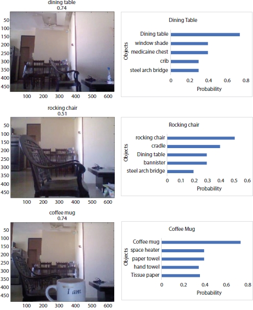
Figure 6.7 Object detection results.
References
1. Nanda, A., Chauhan, D.S., Sa, P.K., Bakshi, S., Illumination and scale invariant relevant visual features with hypergraph-based learning for multi-shot person re-identification. Multimed. Tools Appl., 1–26, 2017.
2. Soomro, K., Zamir, A.R., Shah, M., UCF101: A dataset of 101 human actions classes from videos in the wild, arXiv preprint arXiv:1212.0402, Center for Research in Computer Vision University of Central Florida, Vol 1. 2012.
3. Herath, S., Harandi, M., Porikli, F., Going deeper into action recognition: A survey. Image Vision Comput., 60, 4–21, 2017.
4. Nanda, A., Sa, P.K., Choudhury, S.K., Bakshi, S., Majhi, B., A Neuromorphic Person Re-Identification Framework for Video Surveillance. IEEE Access, 5, 6471–6482, 2017.
5. Aly, S.A., Alghamdi, T.A., Salim, M., Gutub, A.A., Data Dissemination and Collection Algorithms for Collaborative Sensor Devices Using Dynamic Cluster Heads. Trends Appl. Sci. Res., 8, 55, 2013.
6. Yue-Hei Ng, J., Hausknecht, M., Vijayanarasimhan, S., Vinyals, O., Monga, R., Toderici, G., Beyond short snippets: Deep networks for video classification, in: Proceedings of the IEEE conference on computer vision and pattern recognition, pp. 4694–4702, 2015.
7. Schuldt, C., Laptev, I., Caputo, B., Recognizing human actions: a local SVM approach, in: Pattern Recognition, 2004. ICPR 2004. Proceedings of the 17th International Conference on, pp. 32–36, 2004.
8. Murthy, O.R. and Goecke, R., Ordered trajectories for human action recognition with large number of classes. Image Vision Comput., 42, 22–34, 2015.
9. Lipton, Z.C., Berkowitz, J., Elkan, C., A critical review of recurrent neural networks for sequence learning, arXiv preprint arXiv:1506.00019, Vol. 1, pp. 1–38, 2015.
10. K. Greff, R. K. Srivastava, J. Koutník, B. R. Steunebrink and J. Schmidhuber, LSTM: A Search Space Odyssey, in IEEE Transactions on Neural Networks and Learning Systems, 28, 10, pp. 2222–2232, Oct. 2017.
11. Saaid, M.F., Mohammad, A.M., Megat Ali, M.S.A., Smart Cane with Range Notification for Blind People. 2016 IEEE International Conference on Automatic Control and Intelligent Systems (I2CACIS), 22 October 2016.
12. Krishnan, A., Deepakraj, G., Nishanth, N., Anandkumar, K.M., Autonomous Walking Stick For The Blind Using Echolocation And Image Processing. 2016 2nd IEEE International Conference on Contemporary Computing and Informatics (ic3i).
13. Swain, K.B., Patnaik, R.K., Pal, S., Rajeswari, R., Mishra, A., Dash, C., Arduino Based Automated Stick Guide for a Visually Impaired Person. 2017 IEEE International Conference on Smart Technologies and Management for Computing, Communications, Control, Energy and Materials, 2-4 August 2017.
14. Swathi, K., Raja Ismitha, E., Subhashini, R., Smart Walking Stick Using IOT. Int. J. Innov. Adv. Comput. Sci. IJIACS, 6, 11, 1383–1387, November 2017.
15. Saquib, Z., Murari, V., Bhargav, S.N., BlinDar: An Invisible Eye for the Blind People. 2017 2nd IEEE International Conference On Recent Trends In Electronics Information & Communication Technology, May 19-20, 2017.
16. Olanrewaju, R.F., Radzi, M.L.A.M., Rehab, M., iWalk: Intelligent Walking Stick for Visually Impaired Subjects. Proc. of the 4th IEEE International Conference on Smart Instrumentation, Measurement and Applications (ICSIMA), 28-30 November 2017.
17. Hung, D.N., Minh-Thanh, V., Minh-Triet, N., Huy, Q.L., Cuong, V.T., Design and Implementation of Smart Cane for Visually Impaired People, in: 6th International Conference on the Development of Biomedical Engineering in Vietnam (BME6), T. Vo Van and et al. (Eds.), Springer Nature Singapore Pte Ltd, Ho Chi Minch City, Vietnam, 2018.
18. Ali, U., Javed, H., Khan, R., Jabeen, F., Akbar, N., Intelligent Stick for Blind Friends. Int. Robot. Autom. J., 4, 1, pp. 68–70, 2018.
19. Chaurasia, S. and Kavitha, K.V.N., An Electronic Walking Stick for Blinds. IEEE 2014 International Conference on Information Communication & Embedded Systems (ICICES), 2014.
20. J. Meng, J. Zhang and H. Zhao, Overview of the Speech Recognition Technology, 2012 Fourth International Conference on Computational and Information Sciences, Shiyang, China, pp. 199–202, 2012.
- * Corresponding author: [email protected]