Interactive television productions involve and are dependent on a range of technologies – including television sets, transmission platforms and set-top boxes.
The introduction of digital transmission technologies made it easier to distribute interactive television services.
The main transmission platforms for interactive television are digital cable, digital satellite, digital terrestrial and, using digital subscriber line (DSL) technology, the telephone network.
The hardware and software in television set-top boxes usually control the on-screen presentation of interactive television services.
Interactive television services on different transmission platforms often have to be created in completely different ways, using different technologies; they are rarely interoperable. This makes multi-platform production time-consuming and expensive, although the backers of standards like Multimedia Home Platform are trying to address this issue.
“Well informed people know it is impossible to transmit the voice over wires and that were it possible to do so, the thing would be of no practical value.”
Boston Globe editorial, 1865
Successful film directors – Spielberg, Scorsese, Lucas and so on – almost always have a deep understanding of the tools of their trade. They know how to get the most from lighting, the effect of different types of film stock and how to use editing for emotional effect. With this thorough understanding of the technical potential and limitations of the medium, film directors can push the creative and commercial boundaries. The same can be said to be true for interactive television. The technology can look formidable, but focused research into this fast-changing area can bring great creative rewards.
The main challenge with interactive television is that different transmission platform operators use very different technologies and standards are not widely adopted. This can make production complicated, particularly since most of the technology is still at a relatively early stage of development: problems are still being solved and products are constantly being upgraded. And to add to the challenge, interactive television technologies have not simply replaced traditional television technologies: the two are deeply intertwined.
This may change. As interactive television technologies are standardised and production tools perfected, production will become much more straightforward, like regular television. But this is likely to take several years. For the time being, like the best film directors, interactive television producers with a good understanding of interactive television technologies are the ones who are best equipped to create the best possible final results.
Interactive Television Technologies
There are a number of technologies involved in interactive television, all of which can have a dramatic effect on how the end-product looks and works:
The viewer.
The television set.
The transmission network or platform.
The set-top box.
The production tools.

2.1 The technologies involved in interactive television.
This chapter looks at each of these in turn, except production tools, which are covered in detail in Chapter 4. It also goes on to outline some of the issues associated with synchronising video with interactive information and to summarise the main technical standards that are relevant to interactive television production.
The section on television sets and the section on transmission platforms may initially seem rather removed from interactive television. They’ve been included because the technologies of both are instrumental in making interactive television possible and because both have implications for how interactive television services are produced. Interactive television graphics, for example, have to be designed in the right way to work on television screens, while transmission network technologies define the parameters of what an interactive television service can achieve.
If, however, you already understand the basics of how television sets work and the make-up of television transmission platforms, feel free to skip to the section on interactive television set-top boxes.
The Viewer
Okay, so viewers aren’t really pieces of technology. But the ‘biotechnology’ of people’s brains is important for television and interactive television, which both work by playing tricks on people’s visual perception. There are two characteristics of the brain that make these tricks possible. First, human beings naturally look for meaning in anything they see. If an image is broken into a series of dots, the brain will try to put those dots back together into something meaningful. Take a close look at Figure 2.2. If you stare at the image from a few inches away, it’s not always possible to see what it is – the dots (or pixels in this case) are too big for the brain to see as a whole. However, if you move the book further away from you, you can see an image. The brain is able to tie all the dots together into a meaningful whole.

2.2 Difficult to see close up, easier from further away.
The second feature of the brain that makes television possible is that it retains an image for a fraction of a second after it views it – a property called visual persistence. If a series of identical images are displayed quickly enough, the brain won’t see the gaps between them. It will register one persistent image. If you make minor changes to the images, the brain is likely to see these as movement – just like the children’s books that show cartoon figures jumping up and down as you flick through the pages.
There’s more detail on how viewers relate to television and interactive television in Chapter 5.
The Television Set
Scan Lines
A cathode ray tube is at the heart of most television sets. In a standard colour set it fires three beams of electrons at the glass screen at the front of the set. The beams move quickly from the top to the bottom of the screen, hitting photo-reactive chemicals (phosphors) behind the glass and making them glow. Each beam targets a different phosphor – red, green or blue. In response to electrical pulses that represent the brightness and colour of different parts of the picture, the intensity of each beam changes as it moves, making different parts of the screen glow different colours.
The beams move from the top to the bottom of the television screen, painting across it, left to right, in straight lines (called scanning lines) until the whole screen is covered. At the end of each line, the beams turn off and jump to the next line. At the bottom of the screen, the beams turn off and jump back up to the top. The whole process then starts again. This all happens so quickly that the human brain reassembles the collection of thousands of individual glowing dots into an understandable whole – the television picture.

2.3 Electron beams scan across the television screen.
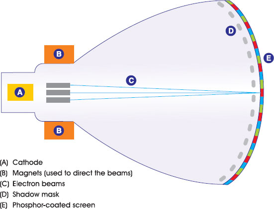
2.4 Inside the television.
Go and switch your television on now and stick your nose a few centimetres away from the screen. On a colour television, you’ll see the thousands of tiny red, green and blue phosphors arranged in dots or stripes. Behind the dots is a perforated sheet, known as the shadow mask. This helps the electron beams strike individual dots cleanly and minimise unwanted illumination of neighbouring dots – a problem that can be caused by very rich colours, and one that interactive television graphics have to be designed to minimise.
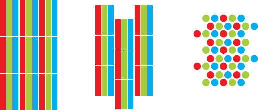
2.5 Various types of shadow mask phosphor patterns.
The next task for a television set is to tie these pictures together to create the illusion of movement. Years ago, movie makers worked out that you need to produce more than 40 pictures every second to fool the brain into thinking the picture is moving continuously. However, these movie pioneers could only work with enough film to get 16–24 frames per second. This is why cinema became known as the flicks: everyone could see the flicker as the frames changed. In cinema, the problem was solved by using special projectors that effectively showed each picture twice – doubling the frame rate to 48 and making the action look much smoother.
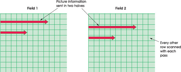
2.6 Interlacing.
The same problem occurs in television. Ideally, you need more than 40 frames per second, but that was too expensive and technically difficult in the early days. To deal with this problem, television pioneers found a clever solution. Televisions paint the screen (and cameras record the image) using alternate lines, completing the picture in two runs. After each run, top to bottom, the electron beams switch off and quickly jump back to the top of the screen to do the other lines. This tricks the brain into thinking that the image is being viewed at a faster rate, and makes any motion look much smoother – even though only half the screen (known as a field) has been drawn each time. The technique, known as interlacing, has a number of implications for interactive television design – particularly when graphics are designed on PC monitors, which update the whole screen with every pass (a technique known as progressive scanning).
Both the unwanted effects of rich colours and the problems for interactive television production associated with interlacing are covered in more detail in Chapter 5.
Country-by-Country Differences in Television Sets
The number of scans per second and the number of lines painted varies between different television systems around the world. Twenty-five whole pictures (50 fields) are built up each second in the European PAL and Secam systems, using 625 lines. In the United States and Japan, which use the NTSC-M system, it’s 30 whole pictures (60 fields) per second, across 525 lines. The difference is partly due to the mains electricity used in the different areas. Television pioneers needed to use the electrical current to synchronise the timing of equipment, so settled for 50 and 60 frames per second respectively, which tied in with the frequency of the mains electricity, 50 Hz in Europe and 60 Hz in the US.
The Transmission Network or Platform
The signal that most televisions require to continuously operate the electron beams contains three main types of information:
Information that can be used to reproduce the colour and brightness correctly for each part of the image.
A synchronisation pulse to tell the television when to move the beams to the start of a line.
A synchronisation pulse to tell the television to move from the bottom to the top of the screen.
Televisions expect to get this information in a particular way, so they can use it to control the cathode ray tube at high speed.

2.7 Close-up view – a signal used by the television to paint one line of the screen.
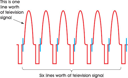
2.8 Several lines worth of television signal.
These television signals can make their way from the location where they are produced to television sets in two forms: analogue or digital. Nearly all televisions eventually work only with an analogue signal to control the intensity of the electron beams. However, before this final stage, the signal can, and often is, converted back and forth between the two forms, on its journey from the supplier to the viewer. Whether a television transmission platform is marketed as digital or not, really depends on the exact points when a digital signal is used – and what actually constitutes a ‘digital’ system is very much a matter of opinion.
Analogue Transmission
With analogue television transmission, the television signals are imprinted directly onto a carrier radio wave, in a process known as modulation. The carrier wave is altered in proportion to the changes in the level of the television signal. An antenna can then pick up the carrier wave and feed it into a television set, which can then extract the original signal and use it to control the electron beam.

2.9 A signal being added to a carrier wave – amplitude modulation.
The Vertical Blanking Interval
In the 1970s, engineers at the BBC realised that some spare parts of the analogue television signal could be put to good use. The extra space, called the vertical blanking interval (VBI), was designed to allow the electron beams to jump back up to the top of the screen after painting each field. It is called VBI because the beams are blanked out during the interval it takes for them to jump vertically from the bottom of the screen to the top.

2.10 The vertical blanking interval (VBI).
The VBI contains pulses that help synchronise the timing of the beams inside the television after they have made the jump from bottom to top. The BBC engineers put some extra signals carrying other information into this. If the television set at the other end was equipped with a suitable adapter, it could read this extra information and, for example, display words on-screen. The BBC started using this space to transmit television listings, news, weather and other useful information. Within a few years, millions of people across the United Kingdom and Europe were using services developed using this teletext technology.
The VBI can also be used for other types of data: subtitles, computer software or even web pages. All that is required is a box inside or connected to the television that can monitor the television signal, interpret any data sent in the VBI and process it in the right way. The VBI is the main delivery platform for interactive television in analogue broadcast environments. Many of the services provided in the United States – for example, versions of Wink TV enhanced television advertising and some versions of the Microsoft TV internet on television system – use the VBI.
The VBI is a particularly good method of transmission for interactive television because it is very easy to synchronise data with the underlying television picture. The data is inherently connected to the frame of video that it is sent along with, as it is carried in the spare capacity for that frame. To put up an interactive icon on-screen, for example, all the broadcaster has to do is make sure the instruction to put up the icon is contained in the VBI lines for the video frame that it needs to appear over. The disadvantage of using the VBI is that there is usually a relatively small amount of space available for data (especially if analogue teletext and subtitles are already being carried). Also, the VBI solution has rather been overtaken by big changes happening to television.
Changing Television
The principles of television haven’t changed a great deal since the first song in the first broadcast from Alexandra Palace in 1936. For anyone that wants to make fundamental changes to the technology of television (like changing the picture size or adding interactive television services), there are basically three choices:
Replace every single television, transmitter and camera in the world with ones that incorporate the new technology.
Try to find a way of piggybacking new technologies on the existing systems.
A bit of both of the above.
The introduction of colour television was achieved by piggybacking the new technology onto the existing system (by squeezing the colour information into the existing black and white signal), combined with a slow upgrade of people’s television sets over the course of the 1960s. Similarly, teletext was created using a space in the television signal that was originally designed for something else, combined with upgrades to television sets. The same sort of combined approach, the ‘bit of both’ option, is happening with interactive television.
On one hand, set-top boxes have been devised that can be used as an add-on to existing television sets. These allow viewers to use new services (like video-on-demand or enhanced television) without having to go to the expense or effort of buying a new television. The television itself doesn’t need to be changed. On the other hand, the owners of television transmission platforms (cable, terrestrial and satellite operators) have replaced their old technologies with newer systems that make interactive television and other improvements (like more television channels) possible. By far the most important of these new technologies is digital transmission.
Digital Transmission
People usually think that digital technology must be a good thing – but often can’t explain why. Marketing executives have capitalised on this confusion and wasted no time branding all sorts of different products as digital: everything from music formats to electric toothbrushes.
Digital Crash Course
The principle behind digital is that information is coded into lists of ones and zeros known as binary. This system has the advantage of being able to be represented by an electric current as either an ‘on’ or an ‘off’.
If you and I are trekking in the mountains and we agree that six blows on a whistle in quick succession (that is, the code 111111) means ‘help, I’m in distress’, then we have devised a digital communication system. Computers, and now television transmitters and set-top boxes, use digital systems. Once a system of meaning has been agreed between the sender and the receiver, almost any type of information can be communicated using ones and zeros – television pictures, computer programs, photographs, anything.
With an analogue television signal, the wave varies according to the intensity of the different parts of the picture. The conversion of analogue television signals to digital ones is done using sampling. Sampling involves breaking the original analogue signal into sections and measuring the signal in each section. Each point in the video signal is then given a binary value (for example 0100 or 0011), representing the size of the sample at that point.

2.11 Sampling.
In the case of the computer programs that are interactive services, the digital data represents the individual instructions that the computer processor running the interactivity should follow, such as what graphics to put on screen. There is no analogue equivalent of this.
With digital transmission, video signals, audio signals and interactive programs all combine to become part of one long stream of ones and zeros. The different types of data are identified by marker codes, which are themselves made up of binary code.
Video and Audio Sample Quality
Digital samples are expressed in terms of the sample rate and the number of bits. The sample rate is how frequently the signal is measured (along the horizontal axis); the bit rate is the number of ones and zeros that can be used to define the size of the signal at each point (giving the level of detail available on the vertical access).
A two-bit sample rate (00, 11, 01 or 10) has four different values, giving any level between 0 and 3. An eight-bit sample (0000 0000, 1111 1111, 0101 0101 and so on) gives up to 256 different levels of signal that can be expressed with the ones and zeros – anything between 0 and 255.
The Benefits of Digital Transmission for Interactive Television
The use of digital technologies for transmission has a couple of big advantages for interactive television services, far surpassing the value of the humble vertical blanking interval in the analogue transmission environment.
The first is that digital data transmission is very robust. Digital data, whether information about a television picture or an interactive service, is attached to a radio carrier wave by modulation (the binary code is transmitted by changing the characteristics of the carrier wave). Although both digital and analogue signals weaken (decrease) as they get further from the transmitter, digital ones will suffer much less from interference. If you’ve ever stood in front of a television with a coat hanger stuck in the back in lieu of an aerial, you’ll know that weak analogue signals cause problems such as double images and ghost images from other channels. However, if the television receiver is close enough to get a signal at all, it should be able to detect whether a one or a zero is being transmitted. So digital signals are more likely than analogue ones to work better across a given distance. It’s like being in the mountains and having to listen for the sound of a whistle rather than hearing the exact words someone is shouting. You either hear the whistle or you don’t. This means digital transmitters need less power than analogue ones in order to cover the same area, making it easier to cover particular regions with a digital signal carrying television channels and interactive television services – and if the viewer normally gets a poor analogue signal, digital could offer a major improvement.
Another major benefit of digital transmission is that more information can be sent to viewers in a given piece of bandwidth (the space in the radio frequency range available for sending information on carrier waves – see the ‘Bandwidth’ definition). This is mostly thanks to the fact that digital television data can be compressed. Basically, to transmit an image using analogue transmission, every pixel has to be represented in the carrier wave in some way. With digital television, on the other hand, systems have been developed that take advantage of the way the brain perceives pictures and motion to remove data that isn’t required. For example, if the background behind a presenter isn’t changing, the information about that background only needs to be sent once – at least until the background changes. The most popular video compression standard with broadcasters and platform operators is MPEG-2 (see ‘In-depth: MPEG-2’). MPEG-2 and other compression formats make it possible to send more channels and to fit interactive services, or anything else, in the space freed up by reducing the size of the video streams. In fact, in the space occupied by one analogue video channel it’s possible to send five or more digital video channels (depending on the quality of picture required).

2.12 Analogue versus digital television transmission. Digital reception quality is mostly better, but will fail more dramatically.
This bandwidth efficiency, more than anything, has led to the massive growth of interactive services on digital television transmission platforms. Interactive television, consequently, tends to be associated with digital platforms – and as digital platforms are built and developed, so interactive television services are built and developed.
It is possible to get interactive television to work on analogue transmission platforms, using the VBI for example, but there tends to be less bandwidth available. Conversely, it is also sometimes the case that digital platforms do not have interactive services. This is usually because the platform is newly launched and the operator is concentrating on getting the television working first, because the platform has very little bandwidth available for some reason, or because the platform is using one of the very early digital formats that doesn’t have the capability to deal with interactive data. This is the case with some of the digital services launched in the 1990s in the United States.
The rest of this chapter refers to interactive television services on digital transmission platforms (although much of the information will be relevant to interactive television services running on analogue transmission platforms as well).
Bandwidth
Bandwidth is the amount of information that can be transferred in a given amount of time. Imagine it as a pipe with water flowing down it – the bigger the pipe, the more water that can flow down it. Interactive television producers often get into arguments with the television platform operators about the amount of bandwidth that will be made available for their interactive service: generally, the more bandwidth that is available, the more features can be added to the service.
In the analogue world, bandwidth is expressed in terms of the section (band) of the radio spectrum that is available or required for transmitting a signal. This is expressed in hertz (Hz), a unit of measurement of the number of changes in state or cycles of a radio wave in a second. An analogue television signal needs around 6 MHz range, or bandwidth, to carry enough information to build a picture (6 MHz bandwidth means there must be enough space to fit in six million cycles per second). To put it another way, if you own carrier waves between 600 and 624 MHz in the radio spectrum, you have enough space to transmit four television channels.
In the digital world, the term bandwidth has been hijacked and changed a little in meaning. Here it refers to the number of bits of information that can be transferred in a given time. A bit is a one or a zero. Broadcast-quality video generally requires around 3 Mbps (that’s three mega, or million, bits per second) once it has been compressed, although this is partly a matter of opinion and depends on the compression system. Some broadcasters use 6 Mbps or more, while others will go as low as 1 Mbps. Using a half- or quarter-screen size or not worrying too much about quality also means the video data can take up much less bandwidth. In the internet world, technologies like Real Video and Windows Media have managed to squeeze watchable video down to 56 kbps (that’s 56 kilo, or thousand, bits per second) and even less, but this is still nowhere near good enough for relaxed living room viewing on a big television screen.
Interactive services usually take up a lot less bandwidth than broadcast-quality video channels. This is because the number of ones and zeros needed to describe a computer program and simple graphics is much less than required to describe a high-quality moving video picture. It’s been known for enterprising broadcasters to run passable digital teletext services in less than 50 kbps (50 000 bits per second) bandwidth. Generally, the more complicated the service and the more content it contains (be that photos, products for sale, text or – worst of all – video), the more bandwidth it will require. Text on its own without photos and graphics generally takes up the least bandwidth (information about how to draw letters on-screen is generally stored at the receiving end, so doesn’t need to be sent in transmission).
Be careful not to confuse bits with bytes. A byte is the information carried by eight bits. Bytes are generally used as a measurement of computer storage.
Digital Platforms
Some Jargon that Platform Operators Use
There are usually two routes for signals and, therefore, the data that makes up particular interactive television services, to get to viewers via digital transmission platforms:
Broadcast via a one-way route, which is used to send information from the broadcaster to the viewer. This is known variously as the one-way channel, the broadcast channel, forward path or in-band channel.
Transmitted via a two-way route, which can be used to send information back and forth between the broadcaster and viewer. This interactive communication channel is variously known as the two-way channel, interaction channel, return path, back channel or out-of-band channel.

2.13 Broadcast channel, return path and the viewer.
The Broadcast (One-Way) Channel
A typical television platform operator will take a range of video and interactive data feeds from different broadcasters (for example, MTV, Sky, CNN) and interactive service suppliers. They will then combine the different bits of data into one signal, in a process called multiplexing, add this onto a carrier wave (using modulation) and send it out to viewers. Basically, there only needs to be one version of each bit of data, as it will be broadcast to everyone.
You may be wondering how interactive services sent by a one-way channel can really be interactive. After all, there is no way for the viewer to send a response or instruction back to the broadcaster. Some commentators don’t believe that it is possible to have ‘true’ interactive television using the broadcast channel. Nevertheless, from the viewers’ point of view, the experience can certainly feel interactive. The way this works is that every single thing that the viewer could do is planned for in advance. All the instructions for these various possibilities are bundled together and sent down the one-way stream. Although the communication is not two-way, it appears so to viewers. Everything the viewer does is followed by what looks like an interactive response. Analogue teletext usually works on this kind of one-way broadcast system, but the pages still appear as if they are arriving to order.

2.14 A one-to-many broadcast system.
There is a limit to the size of interactive information that can be sent in the broadcast stream. That limit depends on the bandwidth allocated. Bandwidth, in this case, is a measure of the amount of data that can be sent in a given time. If a lot of bandwidth is set aside by the operator, then lots of data can be sent quickly – and the viewer will have to wait less time for the interactive service to load and the content to be displayed. If there is very little bandwidth, then less data can be transmitted in a given time. It will then take longer for the interactive service and its content to load. If the wait time becomes too long, the viewer may give up and go and do something less boring instead. The earlier the bandwidth requirements can be planned, the better. A number of UK digital television channels found that in the early days they didn’t allocate enough bandwidth for interactive services and therefore had to limit development – or offer services that ran very slowly.
Most broadcast-channel data that relates to interactive services is sent on a carousel system. This means that once all the data has been broadcast once, it is sent again and again, just like a fairground ride turning around. The data needs to be sent many times on a loop, because it’s often impossible to know when a viewer will need to download a particular item.
The data is often split into two parts:
The application (that is, the master control program for the service).
The data that goes with the application (such as photos, graphics, pages of text and so on).
Whenever a viewer requests a particular interactive service or piece of content, they have to wait for the right blocks of data to come around in the carousel, before they can start downloading it. Any changes to the data made by the broadcaster are reflected the next time that particular piece of information goes out on the carousel.

2.15 Carousel update of interactive data.
Data that is likely to be popular (like the front page of a news service) can be sent more often on the carousel, so it arrives more quickly to viewers. Analogue teletext also usually works on a carousel system: whenever you type in a page number, you have to wait for that page to come around on the carousel and download into the television before it can be displayed on-screen. The front pages of teletext services tend to be included in the carousel more often than other pages.
Popular data can also be pre-stored near the receiver’s end (in a process known as caching). The fast-text function in analogue teletext, which allows viewers to jump quickly (by pressing coloured buttons) to up to four pages linked to the one being viewed, works by pre-storing these four pages in a cache in the television set. This helps increase access speeds.
Multiple interactive services often share the same data carousel.
The Return Path (Two-Way Channel)
With a return path (two-way channel) there is a two-way relationship between the viewer and content supplier. Each time a viewer makes a request for something (for example, a page of weather information), the interactive service supplier is able to act on that request and send the information out. In other words, there is a direct interaction or point-to-point transfer of data.
Return paths can operate at anything from a very slow 2.4 kbps modem (only good for sending the simplest information), to a super-fast DSL line, which is able to carry enough data to construct a high-quality video picture (at the same quality level as might be found in the broadcast channel). Most – although not all – digital transmission platforms include some kind of return path. The ones that don’t have one are limited to providing interactivity via the broadcast channel.

2.16 A return path means the the viewer can talk back to the platform owner.
The disadvantage of a two-way point-to-point model using the return path is that if lots of people request information at the same time, the system can get clogged up. This is the reason that the internet, which is also a two-way point-to-point system, slows down sometimes and on certain web sites, because too many people are trying to access information at the same time.
Interactive television is particularly susceptible to this problem. If a piece of interactivity is promoted on a television programme (using a graphical overlay, for example), lots of people are likely to request that information at the same time. If the data needs to be sent to all of them individually (that is, lots of versions of the same bit of data), it’s likely to cause congestion in the return path. If the information requested takes up lots of bandwidth – video, for example – the problem is likely to be even more severe.
Platform operators sometimes use caching on their return paths to get round this. By pre-storing popular content, there’s likely to be less waiting for data to be transported across the network and less likelihood of congestion.
The other way around the problem is to make sure that any service or content that is likely to be in heavy demand is put in the broadcast channel, rather than sent via the return path. In the broadcast channel, everyone can receive the data without fear of congestion.
Broadband
Broadband is one of those terms that everyone bandies about, but there are often contradictory views on what it means. One definition is that broadband means a two-way connection between a user and an operator, where the bandwidth available is significantly higher than what was available in earlier systems. There isn’t much agreement about exactly what this extra bandwidth needs to be in order to justify the name broadband. Generally, though, if the connection is two-way and over about 250 kbps you won’t embarrass yourself at parties by calling it broadband.
Standards
In the area of interactive television – as in many other forms of telecommunications and technology – certain standards have been agreed to allow manufacturers and broadcasters around the world to build technologies and types of content that work together. This keeps the cost of development down for everyone and makes the industry as a whole more likely to succeed. These useful, but often very dry, standards often have odd names like DSM-CC and MPEG-2.
Because technology is always moving forwards, there are also organisations and groups of engineers who constantly review new ideas to see if they should be included in the latest versions of existing standards. These groups are sometimes formal, sometimes informal, sometimes commercial, sometimes not.
The evolution of standardisation of interactive television is, however, relatively young, compared to the broadcast television and internet worlds – and many standards used by interactive television are borrowed from these areas anyway. Some of the attempts at standardisation are outlined at the end of this chapter.
Whether data for an interactive application is sent via the broadcast channel or the two-way return path, there are a number of standard ways for describing and transporting it. These protocols are effectively the traffic police and taxi drivers of the interactive television world – directing data in the right direction and then transporting it from place to place.
For example, for the broadcast channel, parts of video compression standard MPEG-2 can be used to specify how to carry different types of data in addition to television pictures, while a set of protocols under the rather military sounding name Digital Storage Media – Command and Control (DSM-CC) can be used to control data streams. Certain types of data can also be carried using protocols designed for television listings information. Two different systems for this are DVB-SI and ATSC-PSIP (see ‘In-depth: DVB and ATSC’ later in this chapter).
For the two-way return path, internet standards are often used. For example, internet protocol (IP) is a format for addressing information that is often used by interactive television platform operators. IP addresses are a string of numbers that act as unique identifiers for a particular computer – or, in this case, the interactive television set.
The distinction between one-way broadcast and two-way return path protocols is increasingly blurred. For instance, IP contains a standard called Multicast IP, which allows a single set of data to be sent to many different receivers (effectively a broadcast model using an interactive channel), while, on the other hand, parts of the DSMCC protocol can also be used for one-to-one communication via either channel. It is also possible for data to be dynamically moved between the broadcast and return path channels (for example, in response to changes in demand) and for requests sent via the return path channel to be fulfilled via the broadcast channel rather than back through the interactive channel.
Types of Platform
The main digital transmission platforms that carry interactive television in the United Kingdom are:
Cable. The main operators in the UK are NTL and Telewest.
Terrestrial. The main operator in the UK is a consortium consisting of the BBC, Crown Castle International and BSkyB. The service is called Freeview.
Satellite. The main operator in the UK is BSkyB. The service is called Sky Digital.
The phone network (using DSL technology). UK operators include Video Networks Ltd and Kingston Communications.
Cable
Cable companies use a physical cable connection between themselves and their customers; that’s why they spend a lot of time digging up the streets. Cables can carry lots of data (there is usually a large amount of bandwidth), partly because they are closed systems, protected from interference (from the weather, for example).
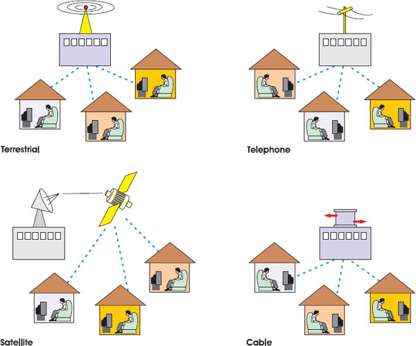
2.17 The different transmission networks/platforms.
Fibre-optic cable, which utilises light for data transfer, is often used to move information around the central parts of the cable company’s network. At a physical location called a headend, bits of data from different sources (broadcasters and so on) are combined and pumped down to customers in a particular area. Big cable companies will have several headends, one for each region. Once the signal reaches street level it is sent down a co-axial cable (it’s generally too expensive to have optical fibre in the home, although this has been tried in some areas). Co-axial cable is so called because it is made of one wire that carries the signal, surrounded by a layer of insulation, plus another wire, which serves as a ground. A network made up of optical fibres and co-axial cables is known as hybrid fibre co-axial (HFC), and is a common mix in the UK.
The advantage of cable platforms for interactive television is that there is usually enough capacity for a high-bandwidth two-way return path as well as a high-bandwidth broadcast channel. Using the return path, cable customers and the cable company can communicate with each other at high speeds. To do this, cable platforms use cable modems. These facilitate two-way communication between ten and 100 times faster than the normal telephone modems that you see attached to personal computers.
2.18 A typical cable platform.
Cable companies will also often provide a separate twisted-pair cable (so called because it is made of two copper wires twisted around each other) into the home, along with the co-axial cable. This is used to provide plain old telephone services (POTS).
The disadvantage of cable platforms for interactive television producers is that the transmission platform only reaches the customers that have cable in their street. This is not a big problem in the United States, where cable penetration is high, but more of an issue in some European countries, where the amount of homes passed by cable is relatively small. The UK arguably has a reasonable cable penetration – around 50 per cent of homes can get it if they want it.
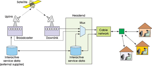
Satellite
Satellite platform operators broadcast their signals from transmitters sitting about 38 000 km (23 000 miles) up in the sky. From this geostationary position, one satellite can transmit its signal to large parts of the Earth’s surface – the whole of Europe along with parts of the Middle East and Russia, for example. As with cable and terrestrial platforms, satellites convey information on carrier signals. Viewers pick up the signal by using directional antennas, commonly known as satellite dishes. These improve the strength of the signal at the reception point. They work by reflecting the radio waves (using a curved surface called a reflector) into the centre of the dish. The radio waves are then converted into signals that are sent down to the set-top box. The bigger the reflector is, the greater the strength of the signal. Digital dishes can be quite small.
2.19 A typical satellite platform.
As with cable, television channels and interactive services are first combined together at a headend. Satellite operators then send the data up to the satellite using powerful transmitter antennas sitting on the ground, known as uplinks. Up at the satellite, the signal is amplified and transmitted back to earth from a transponder. Most satellites have hundreds of transponders, carrying different sets of television channels and other types of communication signal.
The big advantage of satellite is that the only big cost is for the radio bandwidth on the satellite (which is generally hired from the company that owns the satellite) and for the uplinks. There’s no need to worry about digging up the street to every house, or building a network of transmitters around the country.
A disadvantage of satellite is that digital and analogue signals can suffer interference or be weakened by bad weather (particularly rain) and from solar activity. Another disadvantage, particularly for interactive television, is that it is difficult for viewers to send a signal to the broadcaster or platform operator back up via the satellite (unless the viewer fancies having a 100-tonne uplink dish in the back garden – along with a few technicians drinking tea in the shed). To get round this, satellite set-top boxes can usually be plugged into the phone network to allow two-way communication, albeit at a relatively low bandwidth.
Terrestrial
Digital terrestrial television (DTT) uses ground-based transmitters to get radio signals into homes. The big advantage here is that digital signals can be transmitted from transmitters attached to existing installations built for analogue television. Furthermore, viewers are usually able to pick up the signal with their existing aerial. This means that, in theory, the entry costs for digital terrestrial television are low and it should be easy to move people across from analogue to digital using the terrestrial system. In the UK and other countries, the reality has been somewhat different: digital terrestrial systems have been dogged by problems with interference and signal loss. In the UK, the pay-TV digital terrestrial system ITV Digital was forced to close in 2002. Viewers were leaving in droves, which was due, among other things, to people having problems getting a good picture. At the end of 2002 it was reborn as Freeview, which carries less channels and suffers less from picture problems.

2.20 A typical digital terrestrial television platform.
As with satellite, the disadvantage of digital terrestrial is that there is no inherent two-way communication channel. To circumvent this, set-top boxes can be attached to the phone network. Another problem is that there tends to be less bandwidth available in the terrestrial spectrum for data – meaning that digital terrestrial platforms tend to have fewer television channels and interactive services than satellite or cable platforms.
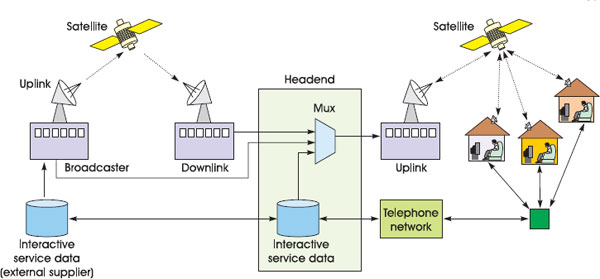
The Telephone and Other Networks
Although cable, satellite and terrestrial are the main ways to get television and interactive services, there are others. Several up-and-coming platforms, such as VideoNetwork’s HomeChoice service in the UK, use the twisted-pair copper wires of the existing phone network. Standard PC-modems already use these wires to communicate with the PC-internet at relatively low speeds up to 56 kbps. However, platforms like VideoNetworks use a new technology, called DSL (digital subscriber lines), which allows data to be transferred over the same copper cables at much higher speeds. One common form, called ADSL (asymmetric digital subscriber line), provides speeds of between 144 kbps and 1.54 Mbps, back and forth between the viewer and the platform provider.
ADSL works by using frequencies to transmit data down the wires that are not required for voice phone calls (in this way, it’s possible to use an ADSL modem at the same time as making a voice telephone call on the same line). The frequencies used for data are then further split up into multiple streams and data is transferred on each one. At the telephone company’s office or exchange sits a box, called a DSL access multiplexer (DSLAM), which combines multiple data streams into a single signal with the outside world.
Satellite and terrestrial operators often work in partnership with telephone operators to offer DSL technologies to their customers. DSL gives these platforms the opportunity to erase the competitive advantage cable has from its fast two-way return path connection. DSL also gives phone companies and platform operators the opportunity to become broadcasters. The bandwidth is enough to provide on-demand and live streaming television channels direct to each customer via the return path – negating the need for a broadcast channel. And the big advantage of DSL, from the customer’s point of view, is that their existing telephone line can provide all this – there’s no need to put up a dish or connect a cable.
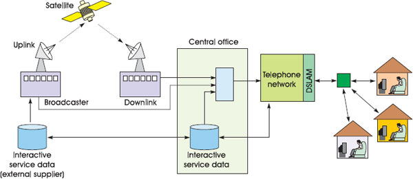
2.21 A typical broadband telephone network.
The disadvantage of DSL is that the distance from the main exchange limits DSL connections. ADSL, for example, is only really possible up to around 5 km from the DSLAM. It is therefore generally only available to people in built-up areas. DSL is also still relatively expensive for the platform provider to install (more expensive even than cable modem equipment).
There are several other less popular (so far) methods for getting television and interactive television into customers’ front rooms. For example, it’s possible to receive data via microwave radio signals to small antennas on the roof (known as wireless cable), via networks usually used by computers (like Ethernet or ATM), and via the electricity system.
Simultaneous Analogue and Digital
Platform operators often transmit analogue television pictures along with digital data. They do this because they can’t change all their customers to digital equipment at the same time. The digital and analogue services are allocated different frequencies – the digital ones tend to be able to occupy space that wasn’t suitable for analogue signals because of problems with interference. As more analogue channels are switched off, additional bandwidth is freed up for digital channels and interactive services.
The most common digital video compression standard used in broadcast television is MPEG-2. Interactive television services often include video streams in MPEG-2 format, so it is worth knowing a little about how it works.
The Moving Pictures Experts Group (MPEG) is made up of a number of industry luminaries and academics who want to standardise digital video and multimedia compression and transmission technologies. It started with only 25 experts but has grown to include hundreds of people and companies from around the world. Many of the participants are involved for academic reasons, others because digital video standards have massive commercial implications for the companies they work for.
MPEG covers a whole family of standards, which are used for different types of data in different ways, each one with a different identifying number (the numbers do not, however, imply that one format is better than the next – just different):
MPEG-1 is used for putting sound and video on CDs.
MPEG-2 is the most widely adopted standard for professional high-quality digital television transmission and is likely to stay that way for some time.
MPEG-4 is used for the transmission of multimedia content across television platforms and the internet (see the ‘MPEG-4’ section later in the chapter).
MPEG-7 and MPEG-21. These are standards for classifying and managing video and other types of data (see the ‘MPEG-4’ section for a little more on these).
MPEG-2 compression works by cutting unnecessary information out of the digital video signal. First, it looks at individual frames and records only enough details to make the picture work on a television screen. (This works in the same way with JPEG images on internet sites, which remove unimportant parts of the image, like the very fine details, to make the file size smaller.) Next it compares adjacent frames and records only the parts of the picture that have moved or changed in some way. If a television presenter is shown against a static background, only the movement of their head and mouth is recorded. Information about the background needs be sent just once – until it moves or changes.
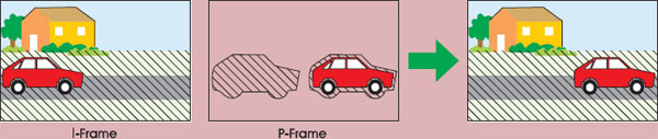
2.22 The I- and P-frames – predicting the picture.
To work the compression across time, MPEG-2 works on groups of frames. The first frame is used as a reference frame and is recorded relatively uncompressed. This is known as the I (or intra)-frame. The I-frame is then used to construct another frame a bit further along in the video sequence. Each part of this frame, known as the P (predictive)-frame, is constructed by looking at the I-frame to see if it is the same. If it’s the same, there is no need for that information to be sent again.
Another smart feature of MPEG-2 is that it can also detect whether something has moved to another part of the screen (a ball flying across the scene in a football match, for example). Then, rather than sending the information again, it simply sends details of where that screen element has moved. The final stage of the process is that the I- and P-frames are compared with the other frames, known as B (bidirectionally predictive)-frames. These B-frames are then compressed at very high rates. To enable all this comparison work to happen, the MPEG-2 coding often reorganises the order of frames, and B-frames are often transmitted after I-and P-frames.

2.23 A group of MPEG-2 frames. The transmission order can be different from the original video and some frames need to contain more data than others.
Interactive services sometimes grab single I-frames for use as part of the user interface (perhaps as a background). It’s possible to send just an MPEG-2 stream with I-frames and nothing else, which can then be picked up and used by a range of interactive services. However, the way MPEG-2 works can also make building some types of interactive television services more difficult. Specifically, MPEG-2 makes it tricky to synchronise interactive content with video content (compared to the VBI, which can carry interactive service information in exactly the right part of the television signal). The problem is that there is no specific part of the MPEG-2 system that defines a frame of video and what interactivity should be associated or overlaid with it. This problem is compounded by the fact that frame order is mixed up and that only I-frames are sent with all the picture information intact.
The new MPEG-4 standard avoids some of these problems, although it is not widely adopted on major digital television platforms. There’s more on MPEG-4 later.
Two of the most powerful television bodies in the world are the Digital Video Broadcasting group (DVB) and the Advanced Television Systems Committee (ATSC).
The DVB group provides a forum for setting standards used for the delivery of digital television content between the different devices in the broadcast chain: multiplexers, transmitters, set-top boxes and television sets. The DVB group aims for interoperability between all the devices in this chain. The standards it has produced for ratification by various bodies (like the European Telecommunications Standards Institute) have widespread acceptance in Europe, as well as South America and Asia.
As well as adopting MPEG-2 as the digital video compression system, the DVB group has developed standards for all the other bits of information that need to be sent between pieces of equipment to make them interoperable. This includes: modulation standards (which have different forms for cable, satellite and terrestrial); a conditional access standard (DVB-CA) that controls access to channels and services; a subtitle standard (DVB-SUB); and a standard for transmitting service information about the programmes and channels contained in the MPEG-2 stream (called DVB-SI).
The DVB-SI (service information) standard defines tables of information that, once transmitted, allow set-top boxes to, among other things, group channels and programmes into categories (like news, comedy and film) and monitor the start time of programmes (so on-screen reminders can come up at the right time). Needless to say, EPG applications tend to make very heavy use of DVB-SI data, although other interactive services can draw on it too. Additionally, some platform operators are starting to use the optional tables in DVB-SI to send extra information about interactivity (for example, whether a television programme has enhanced content and what that content is). DVB-SI tables can only be taken so far, however. The SI structure is not designed for complex instructions. To address this problem, the DVB has defined what could be the most significant standard in interactive television production ever: DVB-MHP. The Multimedia Home Platform (MHP) standard promises broadcasters and content suppliers the ability to create an interactive service once, in the secure knowledge that it will work in the same way whatever digital platform it is transmitted on and whatever kind of set-top boxes it is displayed on. There’s more on this important standard later in this chapter.
The Advanced Television Systems Committee (ATSC) is effectively a rival to the DVB group and is dominant in the United States. ATSC has also been adopted in parts of Asia and in Canada. It initially focused on high-definition television (high-quality widescreen television with more lines and smaller pixels than normal television), but has expanded its remit. As with DVB, ATSC has chosen MPEG-2 as its video compression system. It has also defined modulation and other systems that are required for interoperability between equipment. It has its own equivalent of SI data tables, called the Program and System Information Protocol (PSIP). It also has an equivalent of MHP, called DASE. Unfortunately, although the chosen video system (MPEG-2) is the same with DVB and ATSC, the other standards are a little different. This means that even if Europe and the rest of the world manage to agree a consistent system for creating and displaying interactive services (and even this won’t happen until MHP is widely implemented), these will not necessarily work in the United States and vice versa.
A further complication is that the Japanese have another approach in the form of the Integrated Services Digital Broadcasting (ISDB) standards. This is different again from both DVB and ATSC.
Interactive Television Set-Top Boxes
Digital set-top boxes are one of the keys to the modern communications world. A typical digital set-top box takes digital data and converts it into analogue signals the television can use, runs interactive services and operates stereo sound. Simultaneously, the box manages purchases, protects children from unsuitable material and maintains multiple lines of communication with the outside world. The good ones almost never crash or break down. And sometimes, they are given away completely free – as pawns in great political and commercial gambles.
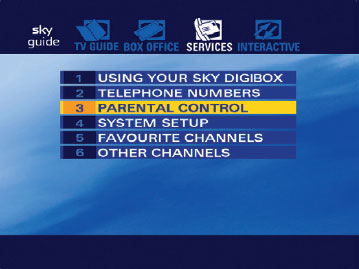
2.24 Parental control systems in the set-top box being accessed using the EPG. © BSkyB.
Most set-top boxes work with an analogue signal or a digital signal, not both; they usually work only on one television delivery platform – cable, terrestrial, satellite or DSL. This is because each platform uses a different frequency range to transmit its television signals and uses different modulation techniques for adding channels and interactivity into a given piece of bandwidth. Hardware in the box needs to be constructed to deal with the modulated signal for a particular platform. It is possible for a box to work with more than one transmission platform, but it requires expensive extra hardware. (It is also theoretically possible with some set-top boxes to add an attachment called a sidecar. This adds the electronics needed to receive an extra platform onto an existing set-top box designed for another platform.) The UK competition regulators have always been keen to enforce this kind of interoperability between set-top boxes and transmission platforms – but have always failed.
Set-top boxes are sometimes integrated into televisions rather than stuck on top of them. These integrated digital televisions (idTVs) have all or most of the functionality of a set-top box incorporated within the normal television electronics.
The set-top box is central to the work of interactive television producers: it makes interactive services happen. The hardware specification of the set-top box defines the capabilities of the interactive services, while the software processes provide the tools for producers to turn their interactive ideas into reality.
Opening the Box: Hardware
Set-top boxes are computers. They use the same electronics and the same basic architecture. However, the hardware inside set-top boxes is often less powerful than on the latest computers, because set-top box manufacturers usually need to keep prices down. This is either because box prices need to be competitive or because a platform operator is going to be subsidising the cost (perhaps even giving the boxes away for free) and will want to minimise the outlay. (Imagine having to justify the purchase of one million set-top boxes in your business plan. It makes a big difference whether each box costs you £250 rather than £350 to manufacture.) The memory and processing power of new set-top boxes usually equates to the home personal computers that people were buying three or four years previously.
Core Components
After the television signal has gone into the set-top box, the first stop is the tuner. The tuner isolates the radio frequencies that carry particular channels of information from the range of frequencies being sent into the box. After the tuner, the radio wave carrying any digital information is sent to the demodulator. This converts the pulses carried on the radio wave into a digital data stream.
Demultiplexer
After the demodulator, a digital box is left with a string of ones and zeros that have been unpacked from the carrier wave. It sends the data to the demultiplexer to be interpreted. The demultiplexer identifies the different elements within the digital stream and separates them. Different parts of the data will be marked up as either information about the video picture, information about the audio, data about programme schedules or data that can be used to build an interactive service.
Conditional Access
After demultiplexing, the box checks whether the television channel or interactive service in the data stream have been paid for by the set-top box owner or – more crucially for parents – whether it needs to be protected with a password screen. All this is handled by the conditional access (CA) system. This compares the type of programme, channel or interactive services against a list of services that the set-top box owner is allowed to access. The conditional access system also deals with any video signals or interactive services that are sent in a specially encrypted form to protect against unauthorised use. It decrypts these, before passing them on.

2.25 The physical hardware inside the set-top box.
The different bits of digital information are sent to appropriate parts of the box for specialist processing. The video data is sent to a video card. This converts the video data back into a signal that the television can understand. The signal is then sent out to the television via a Scart (or similar) or turned back into a radio signal and sent via the RF lead. The video card works in close conjunction with an audio card, which deals with the audio sections of the data stream and converts it into an output that is suitable for home hi-fi.
CPU and Memory
Any interactive data segments, which could be television listings information or interactive services, are sent to a data decoder, which marks them up for appropriate action by the central processing unit (CPU). The CPU, with its processor chip, is the brain of the set-top box. It manages all the hardware components, runs software programs and monitors for problems. The CPU also has access to a graphics processor and to memory. The graphics processor renders interactive text, colours and pictures to the television screen – it is the core display tool for interactive services.
There are several different types of memory in a typical set-top box, each of which performs different functions. Random access memory (RAM) is used as a temporary storage area. When the set-top box is switched off, information held in RAM disappears. Read-only memory (ROM), on the other hand, keeps its information when the set-top box is switched off, but capacity is usually very limited. There are two particular types of ROM memory that set-top boxes use. The first is called EEPROM, which holds information permanently on chips and is typically used to hold the programs that are required to start the set-top up. The other is Flash memory, which can be erased and reprogrammed more easily than EEPROM. Flash memory is used for computer programs that need to be constantly available in the box but might need to be changed – upgrades to the core software, for example.
Some set-top boxes (such as the TiVo and Sky+) have extra storage capacity. These use personal computer-style high-capacity hard drives (and sometimes other storage devices) to record television programmes and interactive applications for later use. This hard drive makes it possible to record, stop, rewind and forward wind television programmes at any time. And it makes it possible to store very large interactive applications, like 3D games. Some games consoles (like the Microsoft Xbox) have similar functionality. See the TV Anytime section towards the end of this chapter for more on these personal video recorder (PVR) technologies.
External Communication and Interfaces
Most set-top boxes receive most information via the broadcast tuner. However, there are other ways for the boxes to receive and send information.
Smart Cards
Most set-top boxes contain a smart card reader (usually in the front panel). Smart cards store information about the channels and interactive services to which the user has subscribed, and keep a running total of pay-per-view programmes or pay-peruse interactive services. The conditional access system then draws on this information in deciding whether a viewer is allowed to use a service.
Pay-per-view services typically work by keeping count of the number of orders on the smart card using a token system. Each time the user views a video programme (such as a boxing match or some porn) or uses an interactive service that needs to be paid for, one unit is removed from the balance on the smart card. Once all the tokens are gone, nothing more can be ordered. Periodically, the platform operator checks the content of the smart card via the two-way return path, adds the price of the tokens used to the customer’s bill and resets the token balance. If the box isn’t connected to a two-way channel (a phone line or other means of sending information back to the operator), the pay-per-view operator will require the viewer to contact customer services using a telephone. In this case, the central office, not the smart card, records the number of movies viewed and sends permissions to the conditional access system in the broadcast stream.
Smart cards can be taken in and out of the box, although the latest versions will code themselves electronically to a particular box the first time they are used and will not work with other boxes. (With these new boxes it’s no longer possible to take a smart card over to your friend’s house or down the pub so you can all watch the big game there).
Advanced smart cards can also be used as electronic purses. Although still quite rare, viewers can deposit money onto these cards (using, for example, a specially adapted bank cash point), then slot them into the box to spend the money on various services. Alternatively, some set-top boxes have credit card readers. These can be used to read the identity information off credit cards. Viewers can then make purchases at home simply by slotting the credit card into the set-top box.
Development of the smart card was the basis for much of the modern UK pay-per-view environment: it enabled Sky Digital to charge for football and movies, and to make the content exclusive. However, smart cards have to be continually evolved to keep ahead of a flourishing counterfeit operation.
Modems
The modem in a set-top box allows communication back and forth with the outside world via the return path, by modulating and demodulating data onto a carrier wave. There are many species of modem, which use various standards for communicating back to base and with the outside world, based on the type of modulation they employ. These include the V.22/V.22bis standard used in modems in older set-top boxes, with transfer rates no more than 2400 bps, all the way through to V.90 and K56Flex standard that can send and receive information via the phone line at speeds up to 56 kbps.
Cable modems use one of two main standards. The United States-based Multimedia Cable Network System (MCNS) has developed a standard called Data Over Cable System Interface Specification (DOCSIS). The European-based Digital Audio Visual Council (DAVIC) has its own alternative. Theoretically, cable modems can squeeze around 30 Mbps out of a cable line, but in reality viewers usually get up to 1.5 Mbps or so, which is sometimes shared between several people on the same street. Cable companies will also sometimes put limiters on cable modem connections, keeping them down to 512 kbps or less, useful to stop your customers running their own internet service providers from their living rooms.
ADSL modems, which squeeze large data-transfer speeds out of copper telephone wires, use either the discrete multi-tone (DMT) standard or the carrierless amplitude phase (CAP) system. Both these provide up to around 1.5 Mbps into the home.
With most types of modem, the bandwidth allocated or available to send data from the platform operator to the customer (known as downstream) is usually higher than that between customer and platform operator (known as upstream). This reflects the fact that it is the operators that normally send the bulk of data, in response to relatively small (in data terms) requests from viewers.
Interfaces
Interfaces are added to set-top boxes to extend their functionality to other devices. Interfaces also help to make a set-top box future proof. As functionality and new devices are developed, these can be added to the original box using the different interfaces.
Boxes often include one, two or more of the following:
Parallel (known as IEEE 1284) and serial (known as RS-232) ports, so they can be connected to printers and devices that don’t need terribly fast data-transfer rates.
Universal serial bus (USB) interfaces, which can be used for a wide range of equipment, from scanners to hard drives to networking.
The relatively new IEEE 1394 (sometimes known as Firewire) interface, for attaching kit that requires high rates of data transfer (like video cameras).
Common interfaces, which take hardware modules like the Personal Computer Memory Card International Association (PCMIA).
Base-T (Ethernet) connections, which have been used for years in offices to network computers.
Bluetooth and other systems that enable wireless communication between devices.
Unfortunately, just because a set-top box has some of these great interfaces doesn’t mean they actually work. The manufacturer of the set-top box, and the people who make equipment to plug into them, often have to do quite a lot of software development to get them working. Consequently, set-top boxes often come with interfaces that do not have drivers (the software in the set-top box that tells the box how to access the interface). They are therefore useless. Manufacturers and platform operators put the interfaces on the boxes with the expectation that they may make them work at some point in the future.
Remote Controls
Viewers can send instructions to set-top boxes to perform functions using infrared (IR) remote controls or IR keyboards. Set-top boxes themselves can also tell video recorders and other devices what to do by using IR blasters. This is a remote control that is fitted to the set-top box, so it can send out its own instructions.
Infrared waves are just past visible light on the electromagnetic spectrum (and just before micro and radio waves), and so a line of sight between the sender and receiver is required, although bouncing the signal off walls is possible.
Wireless keyboards are designed to sit on people’s laps and are usually much smaller than personal computer keyboards – they are a must-have for anyone who wants to write a lot of emails using their television. There are also a variety of other devices that can work using IR, from joysticks to speakers, removing the need for ugly cabling to be strung across the front-room floor.
One interesting piece of technology allows set-top boxes to work with and identify more than one remote control. Each remote is given its own unique identification code in the IR signals it sends. This facilitates games being played on television by different members of the family at the same time – and the set-top box can tell whether Mum or little Johnny answered the on-screen question correctly.
Opening the Box: The Software
Software programs are the building blocks of interactive television. Interactive television producers tend to have a much closer working relationship with set-top box software than anything else.
Software, processed in the CPU, manages the hardware on the set-top box, communicates back with the platform operator, and controls the presentation of information and interactivity. Although interactive television software can work in many different ways, the structure is broadly the same across almost every set-top box. This structure is composed of three key elements, which work in layers:
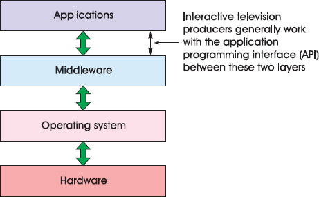
2.26 A typical set-top box software architecture.
The Operating System
The foundation layer of set-top software architecture is the operating system. This performs broadly the same function as Windows XP and Mac OS X on personal computers. The operating system controls the use of the CPU, tells the various bits of hardware what to do, manages communication around the box, monitors use of memory and generally makes things happen. However, in the case of set-top boxes, unlike personal computers, the operating system does not usually provide an on-screen interface for users to be able to control various parts of the underlying system – television viewers don’t need this level of access.
Operating systems are usually held in ROM memory and kept running at all times – although the platform operator can make upgrades to the operating system by downloading new software into Flash memory. (Depending on the amount of Flash memory available, this can involve stopping the box working for a while as the upgrade is made, or switching between two sets of Flash memory to allow the box to keep working while the upgrade is made.) Set-top box operating systems are usually designed to be able to take up very little space in terms of processing power and memory (they have a small ‘footprint’ in technical terminology), because they need to work on cheap and basic boxes that aren’t very powerful.
There are a number of elements that make up an operating system. There’s the kernel, which is the core of the system. It includes the most basic functions, such as the ability to manage memory and transfer data. There’s a program to allow the operating system to run more than one task at a time (known as multi-tasking), a loader (used for searching for and integrating upgrades and other programs) and different drivers (control programs) for the different pieces of hardware in the box. In addition, there are sometimes programs, known as resident applications, that are stored permanently in the set-top box and that work in close conjunction with the operating system.
There are a wide variety of set-top box operating systems. They tend to be written to support particular processors. Examples include Windows CE, Linux, pSOS and VxWorks. It is unlikely that an interactive television producer will ever need to access the operating system functions directly. This is because there is software that talks directly to the operating system that is specially designed for producers of interactive television services: middleware.
Middleware
Middleware takes all the worry out of developing interactive services by doing two things. First, it communicates with the operating system in a controlled way, which reduces the possibility of interactive services crashing the box or damaging the hardware. Second, it provides a standardised system of commands and programming tools. Interactive service producers have no need to worry about the way the operating system works or details of the hardware in the set-top box – the middle-ware works all that out. The middleware programming language will also be consistent, whatever platform or hardware the particular middleware is used on (be it cable, satellite; advanced or basic set-top box).
There are a number of different types of middleware on the market, including OpenTV, Canal+ Technology’s MediaHighway and Liberate’s TV Navigator. Each brand of middleware on the market is significantly different – both in the way they are built and in the way that interactive television producers communicate with them to make things happen. This means that although middleware means that producers don’t have to worry about different set-top box specifications, it can be time-consuming and expensive to produce services for more than one type of middleware. Writing the code is often the most time-consuming part of any interactive television project. And rather than an application working automatically across the different types of middleware, it often has to be rewritten from the ground up for every single one.
Table 2.1: A selection of middleware systems
Middleware |
Produced by |
OpenTV |
OpenTV (www.openTV.com) (Used in Sky Digital set-top boxes in the UK) |
TV Navigator |
Liberate (www.liberate.com) (Used in NTL and Telewest digital set-top boxes in the UK) |
MediaHighway |
Canal+ Technologies (http://www.canalplus-technologies.com) (Used in some digital terrestrial set-top boxes in the UK) |
MicrosoftTV |
Microsoft (www.microsoft.com/tv) |
PowerTV |
PowerTV (www.powerTV.com) |
CableWare |
Worldgate |
Netgem |
Netgem (http://www.netgem.com) |
The method of communication with the middleware is known as the application programming interface (API). APIs allow producers to create the computer applications that viewers actually use (like EPGs, email, games and enhanced television). They do so by calling on functions of the middleware and, through the middleware, the functions of the hardware in the set-top box.
Some types of middleware use APIs that are based on computer programming languages (like Java or C). A programmer with some knowledge of the language should be able to learn the API specific to interactive television after some extra training. Other types of middleware provide special application development toolkits. These offer PC-based interfaces and short cuts that make creating the programs and content templates easier than using raw computer programming code. There’s more on this in Chapter 4.
Virtual Machines/Engines
Some middleware producers, in an attempt to make their systems very easy to use, have built software modules that allow the middleware to be controlled using existing and well-known programming or content markup standards.

2.27 A virtual machine sits inside the middleware.
A programmer with knowledge of the language will be able to use the module without any extra training. These environments are known as virtual machines or engines. Some of these work very much like mini-middleware systems, with wide-ranging functionality; others (known as presentation engines) are only designed to display information on-screen. A virtual machine created by two different middle-ware suppliers can be programmed in exactly the same way, as long as they are designed to work with the same programming standard.
There are a number of different types of virtual machine/engines. For example:
Java virtual machines can be used for developing advanced programs based on the computer language Java. A Java virtual machine is at the heart of the Multimedia Home Platform middleware standard.
WML presentation engines that layout pages of WML, a low-bandwidth markup language similar to HTML but originally designed for mobile phones. (This works particularly well in the television space because the data required for WML takes up so little broadcast bandwidth.) Sky Digital in the UK has a WML engine running in the OpenTV middleware.
HTML and JavaScript presentation engines. The middleware supplier Liberate, a company that was spun out of the PC-internet browser company Netscape, has HTML and JavaScript presentation engines running right in the heart of its system, called TV Navigator. Developers can build applications using the tools Liberate provides or just write code using the same text editor that they use for creating web sites (or even using extensions to off-the-shelf layout programs like Dreamweaver – although this only works for simple interactive television services). The digital cable platforms in the UK use the TV Navigator middleware.
MHEG-5 presentation engines. MHEG-5 is a standardised way to represent multimedia content on television, sanctioned and developed by the Multimedia Hypermedia Experts Group – an organisation set up by the International Standards Association (ISO) for storing, exchanging and displaying multimedia content. MHEG-5 was adopted by the Digital Television Group as the standard for interactivity to be used in the digital terrestrial environment in the UK. Digital terrestrial television set-top boxes and televisions in the UK generally have presentation engines that can understand MHEG-5.
Set-top boxes can sometimes switch between different virtual machines if required. And powerful set-top boxes can run two or more at once. Interactive television producers can then choose which virtual machines or engine to work with, or whether to work on the middleware directly.
Server-Side Technologies and thin Clients
It is not necessarily the case that all the important software (like the middle-ware) has to run on the set-top box. Certain platforms have so much bandwidth available between the platform operator and the viewer that it is possible to produce a very cheap set-top box with almost no memory and processing power. Known as a thin-client, these type of boxes do nothing other than run the most basic functions. Powerful computers at the platform provider’s office (the server side) run most of the middleware and interactive functions, and instruct the set-top box (the client side) directly what to put on-screen. This obviously only makes sense if there’s lots of bandwidth available and the price of set-top boxes has to be kept to an absolute minimum.
Applications
Applications are the software programs that run the interactive television services that viewers actually use. These are what interactive television producers build: electronic programme guides, video-on-demand services, digital teletext services, walled gardens, shopping services, information sites, internet access interfaces, different types of enhanced television and so on. There’s more on producing interactive television applications and how to develop for different types of middleware in Chapter 4.
Synchronisation of Video and Interactive Content
One of the most difficult problems that interactive television technologists have had to solve is how to synchronise interactive content with the digital video streams. This is important for a number of applications, including interactive television advertising (where the viewer has to be prompted to do something at exactly the right time during a 30-second slot), enhanced quiz shows and enhanced sporting events involving predictions during the game. There are two key issues that need to be addressed:
The problem of how to bring up the first interactive graphic on-screen at exactly the right time (for example, an overlay graphic that says, ‘Press Red now for interactivity’).
How to keep any subsequent interactive overlays in synchronisation with the video stream.
2.28 The ‘red button’ prompt has to appear on-screen at the right time. Courtesy of Carlton Active.
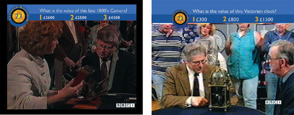
2.29 During this enhanced version of Antiques Roadshow, the viewers had to guess the value of each item. The interactive options need to be synchronised very closely with the underlying video. Courtesy of the BBC and BBC TV Antiques Roadshow.
Taking the example of an enhanced television quiz show, the first interactive prompt has to be put on-screen at the start of the show. The viewer then has to choose answers from on-screen overlays to questions from the presenter in the video. The different answers need to appear at exactly the right moment and disappear before the next question is asked. The challenge is that they need to come up at the right time across the whole broadcast network, even if viewers in one part of the country are liable to get the video signal a fraction of a second after others (as happens sometimes on cable and digital terrestrial television platforms). They also need to appear at the right time, even if the advertising break runs for an extra two seconds or if the programme starts late because the sports event beforehand overruns.
Unfortunately, MPEG-2, the most common form of video compression used by broadcasters and platforms, doesn’t have a standard method for including synchronised interactivity with the broadcast data stream (unlike MPEG-4, which is designed to tie in very closely with interactivity, but isn’t widely used by television operators). Therefore, digital platform operators have had to define their own solutions, while working with standards bodies (like MPEG, DVB, the ATV Forum and ATSC) on systems to deal with the problem.
The result is that there are a very wide variety of ways that digital transmission platforms are addressing the synchronisation issue. However, taking a very high level approach, it is possible to describe a broad synchronisation architecture that will apply to at least some of the systems currently in use. Although the terminology varies, what many of these systems do is graft an interactive play-out architecture onto the existing video play-out data stream. This is achieved by adding up to three new streams of data to the existing broadcasts. These can be called:
The announcement stream.
The trigger stream.
The content stream.

2.30 In this enhanced sports programme, after a suspected foul an overlay comes on the screen at the right time. Viewers can submit their prediction for what will happen right up until the referee makes a decision. © BSkyB.
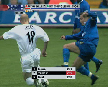
2.31 After the ref makes a decision, if the viewer made the right prediction he or she wins points. © BSkyB.

2.32 A broadcast architecture for synchronised enhanced television.
An announcement stream is a relatively low-bandwidth flow of data that tells the settop box that an interactive application needs to start and where the instructions for how to run that application are held. A process in the set-top box middleware needs to be running at all times to monitor this announcement stream. If the process sees that an enhancement needs to start, it instructs the middleware to direct more of its attention to the place where the television programme’s interactive triggers and content are held. The announcement stream is usually in a proprietary format, although some work has been done with integrating announcements into the programme information tables defined by the DVB-SI and ATSC-PSIP.
The trigger stream is where the middleware looks, after it has been told to pay attention by data in the announcement stream. The trigger stream is a flow of data that contains information about the exact time interactive icons need to be shown on-screen throughout the programme. It will contain instructions like ‘put this icon on-screen at this point in the programme for this amount of time’. Trigger streams can also contain information that will move overlays or events back or forward in time if the programme is delayed or if the triggers go out of synchronisation.
The content stream (which can be in the broadcast channel or return path) carries content that the application can pick up when necessary during the programme.
For pre-recorded programmes that are unlikely to change in start time or length or unlikely to have their advertisement breaks changed, the process of timing triggers to put up overlays is relatively straightforward. The first overlay and subsequent overlays can be set off at particular times, synchronised to clocks in the programme information streams or in the set-top box. However, for live programmes (like a sporting event), where overlay triggers have to be moved frequently, the process can be a lot more complicated. The synchronisation of interactivity to live programmes usually requires either several people managing the overlays or complex content management systems – or both.
Attempts at Standardisation
There’s a gaggle of technology standards that are particularly relevant to interactive television production. Most are still in their infancy and none of the main ones are adopted globally. But with powerful organisations like DVB and ATSC behind some of them, it may only be a matter of time. Here are some of the standards that are worth watching.
Multimedia Home Platform
Members of the DVB group realised some time ago that it would be difficult and expensive for content providers to produce commercially successful services if they had to rebuild them for all the different middleware programs (be it OpenTV, Liberate or MediaHighway) used on the big platforms. This has certainly been the case in the United Kingdom, which has three different digital platforms that all use different types of middleware. Only the richest providers have been able to afford to produce services for all three.
In an attempt to get round this problem, the DVB-Multimedia Home Platform (MHP) specification defines standard ways for interactivity to work across different platforms and across different set-top boxes. MHP defines not only a structure for the middleware software and its application programme interfaces (APIs), but also defines all the other areas needed to create interoperable interactive services (including data transport protocols, hardware requirements and content types).
The middleware definition part of MHP is so detailed that MHP is often referred to as a middleware itself. However, because it is standardised and completely open (the specification is published on the internet for anyone to see and use virtually royalty-free), each existing middleware supplier is free to adapt its own product so it fits the MHP specification. This is exactly what OpenTV, Liberate, Canal+ and others have done and there are a number of MHP-compliant middleware products on the market.
When, eventually, all the major middleware suppliers and digital platforms adhere to the MHP specification, interactive television producers will only need to author a service once. It will then work on all the different broadcast systems around the world that adhere to MHP. Great stuff. The only problem is that MHP requires a reasonably powerful set-top box to work (it can take lots of memory) and can use lots of bandwidth. And, unfortunately, many viewers already have set-top boxes that aren’t powerful enough to run MHP. And these can’t be upgraded overnight. Consequently, the MHP standard is likely to be rolled out gradually over a period of many years, as new platforms are built and set-top boxes in people’s homes are upgraded.

2.33 The DVB-MHP – the technical spec.
MHP can be seen in action on a number of the newer and more advanced European interactive television platforms. It has also been adopted by CableLabs, the research and development consortium representing American cable companies. CableLabs has made it the middleware choice for its OpenCable digital set-top box standard.
The MHP specification has three areas, or profiles, that define different types of interactivity. The profiles are:
Enhanced broadcast.
Interactive broadcast.
Internet access.
In DVB terms, the enhanced broadcast profile is the simplest. It focuses on providing standards for interactivity predominantly via the broadcast stream, in a way that ties the interactivity in with television channels. The DVB-MHP group has specified that a Java virtual machine (called MHP-J) is the primary tool for creating enhanced broadcasting content. Java is a powerful language created by Sun Microsystems, but it can be used without paying royalties. The disadvantage of Java is that its virtual machines can take a lot of memory to run.
The interactive broadcast profile adds more standards to fully utilise a two-way return path, such as internet protocols (IP). Both profiles 1 and 2 also have an optional method for allowing set-top boxes to display HTML.
The final, most complex, profile focuses very much on internet on television. It specifies methods for broadcasting internet content and the particular internet programming standards that MHP set-top boxes will need to understand. These include HTML, ECMAScript (which is the basis of the JavaScript language that is used to add animation and interactivity to web sites) and cascading style sheets (CSS), which is a method for making changes to multiple internet pages by changing the code in only one place, making it much easier to make bulk changes. There’s more on the tools needed to produce an MHP-compliant interactive service in Chapter 4.
DASE
While the DVB has been developing the MHP standard, its United States equivalent, the Advanced Television Systems Committee (ATSC), has been developing its own version: the Digital Television Applications Software Environment (DASE). The DASE standard is very much like MHP in that it defines a way to produce both layouts and more advanced code. It also includes specifications for the other aspects of interactive television production that are required to make services interoperable across different platforms and middleware.
Like MHP, DASE has chosen HTML and JavaScript as the layout formats. Also like MHP, DASE uses a Java virtual machine as the mechanism for producing more complex interactivity. Unfortunately, there are some differences between the two standards, and DVB-MHP and ATSC-DASE are not specifically designed to be inter-operable. This means that a service built to work on MHP middleware will need to be changed to some extent to work with DASE.
ATVEF and the ATV Forum
The Advanced Television Enhancement Forum (ATVEF) was born in the United States in 1997. It consists of a variety of television and technology companies interested in standardising the way interactivity is authored for television and other receivers (like personal computers with video cards).
ATVEF’s most important piece of work defines a set of content formats and delivery mechanisms required to get internet pages from broadcasters to viewers. In contrast to MHP, ATVEF is totally focused on languages that define how the screen is laid out (that is, HTML and JavaScript), not ones that can run complex processes and algorithms. ATVEF does not cover languages like Java, which can be used for this kind of complex programming.
Pretty much everything in the ATVEF standard is based on internet technologies. The idea is that broadcasters can create interactivity in languages that are well understood (that is, HTML and JavaScript) using familiar content formats (like jpeg, gif and so on). ATVEF also has specifications that standardise the way interactive content is synchronised and delivered via video streams.
ATVEF delivery mechanisms are called Transport A and Transport B. By defining how these streams work, ATVEF aims to provide a level of consistency across platforms, allowing synchronised content to be created without producers having to be too concerned about the detail of the broadcast systems:
Transport A defines a standard for a delivery platform where the triggers for interactivity are included in the broadcast stream but the content is sent via a separate return path (for example, a modem in a set-top box).
Transport B defines a delivery platform where announcements, triggers and content can all be sent in the broadcast stream.
ATVEF is no longer active. But the work of promoting the standards that ATVEF devised and of promoting interactive television using internet and open standards has been taken over by an offshoot body, the ATV Forum.
MPEG-4
The Multimedia Hyper Media Experts Group (MPEG) has defined a range of different video compression standards for different purposes. MPEG-4 is a standard designed especially for multimedia applications. It is particularly useful for interactive television programmes that require synchronisation between video content and multimedia content (such as timed overlays, on-screen prompts and interactive advertising).
The advantage of MPEG-4 is that a platform operator does not have to work out its own play-out system architecture to make synchronised interactivity work (for example, by adding trigger and announcement streams). All the systems required to tie in interactivity with the video are defined within MPEG-4.
Another advantage of MPEG-4 is that it is designed to work well across a range of bandwidths. So, if the video material can only be sent over a narrowband pipe, with very little room for data (for example, an internet connection using a 56 kbps modem), it will adjust the video to work within these parameters. Equally, if the MPEG-4 signal has plenty of bandwidth (a satellite broadcast channel, for example) then the video picture will become high quality. In fact, high-bandwidth MPEG-4 is comparable to MPEG-2 video, even though MPEG-2 was designed specifically for professional broadcast-quality bandwidths. (MPEG-2 produces an excellent picture when there is plenty of bandwidth available, but doesn’t really work at all once the bandwidth starts to become limited.)
MPEG-4 also defines standard ways to represent virtually any unit of sound, video or multimedia content that could be needed. Called media objects, these can be recorded with a camera (for example, a presenter reading the weather) or created by a computer (for example, a three-dimensional computer character of a presenter reading the weather). The objects can then be manipulated in a huge variety of ways by the broadcaster or the viewer. Taking just one example, within MPEG-4 data there can be instructions to treat a weather presenter as an object. The viewer could then decide to change the background that the presenter is on – perhaps he or she wants a forecast from a paradise island rather than a rainy studio rooftop. Or the broadcaster may decide to change the accent of the presenter depending on where the show is being broadcast.
Although the standard is well defined, it is not widely adopted on television transmission platforms. The platform operators are having enough trouble getting their transmission networks, broadcast partners and set-top boxes to work with MPEG-2, without worrying about new functionality. The standard also covers many different things and, to run it all, the set-top box would have to be super-powerful.
It’s also worth quickly noting two other MPEG standards:
MPEG-21 addresses the issue of how multimedia content in different formats (like MPEG-2 and MPEG-4) is used across several different platforms – not just television. It’s a high-level standard for people who own platforms.
MPEG-7 offers ways of describing and cataloguing multimedia content, so it can be easily searched and retrieved.
MPEG-7 is particularly relevant to personal video recorders and has been drawn on heavily by one of the standards bodies dealing with these – the TV Anytime Forum.
TV Anytime
The TV Anytime Forum is dedicated to producing standards for set-top boxes with personal video recorder (PVR) functionality. These boxes can store programs and other data on hard disk or other storage media for later viewing. TV Anytime aims to make all the personal video recorders that come onto the market interoperable. They hope that, ultimately, viewers will be able to plug their new boxes into cable, satellite or terrestrial without any problem, and platform providers will be able to relay one set of standardised signals to help customers make use of advanced personal video recorder functions.
TV Anytime addresses a range of useful personal video recorder functions. Foremost among these are the standards for metadata – or data that describes other data. Metadata, among other things, allows television programmes to be broken up into segments, each identified by particular data packets (the metadata). The metadata for each segment describe exactly what the segment is about and how it can tie in with other programmes and segments. Viewers can then set their personal video recorders to, for example, capture just the sports stories from a number of news programmes across several channels; use metadata to help manage Star Trek collections; or add a personal bookmark in a film, so it is possible to jump back quickly to the same shot again and again.
Another element of the standard applies to rights management. This can be used to stop viewers illegally copying films and sending them to their friends, perhaps by using a recordable DVD attached to the personal video recorder. One part of the standard also defines how programmes can be tagged so that they only play a set number of times or so they only play on a particular piece of equipment.
All this wonderful technology counts for nothing, of course, if the people footing the bill don’t see some kind of return on their investment. Next: making that return.
Case Study: MTV Europe Music Awards
Rod Clark, technical consultant, NDS. NDS is a supplier of end-to-end digital pay-TV solutions for the secure delivery of entertainment and information to television set-top boxes and personal computers.
MTV Networks Europe wanted to create new revenue streams, attract more viewers and add a new dimension to the viewer experience through a range of innovative and exciting interactive services. They therefore decided to broadcast the 2001 MTV Europe Music Awards with a difference. The partnership between MTV and NDS enabled viewers to actively participate in determining the results of the awards by allowing them to vote with their remote control. To further enhance the awards event, viewers could also enter daily quizzes, read about the artists and take a look at all the latest news during the run-up to the MTV Europe Music Awards.
Reinforcing MTV’s position as the leader of music television, the success of the European Music Awards interactive applications has substantiated the value of this service and the relevance to the MTV audience. The success of the interactive television service has been recognised at the Revolution Awards in 2002 with MTV receiving the award for best interactive television service.

2.34 The MTV Europe Music Awards with technology by NDS. © MTV.
The MTV audience is used to interactivity and expects high standards, and this high-profile event was certainly no different. Within demanding timescales, NDS delivered the technology that successfully processed 710 000 votes between the 5th and 8th of November.
The service was developed by NDS in partnership with MTV, using the Value@TV solution. This system provides standard interfaces for interactive data broadcasting and return-path applications on a multi-platform basis. The NDS infrastructure is flexible and can be configured to support whichever return-path provider is chosen. This meant that MTV were offered the choice to shop around for a return-path partner that best suited their requirements.
The application as a whole was broken down into three different stages:
Pre-Europe Music Awards (EMA).
Live EMA.
Post-EMA.
The pre-EMA stage launched at the start of the week of the event and gave the viewer even more control over the results. Viewers were allowed to vote in 12 different categories, browse through several pages of latest news, read about information relating specifically to the event and were given the opportunity to win a prize in a daily quiz. The data for this stage was all prepared in advance where possible and delivered to the headend as an XML file for compilation. Nominees for the awards were sent from the set-top box, via the point of presence computer (a connection point to the network), to BSkyB’s authentication server and via the interactive router at the headend to be collected by one of MTV’s application servers. These results were then analysed offline and stored for future broadcast.
The live EMA stage of the interactive service enabled viewers to vote for a new award for the best live performance. This gave the interactive television user the opportunity to influence the choice of artist selected for an evening special on the United Kingdom channel.
The post-EMA stage provided similar functionality to the pre-EMA stage. Again, a quiz was available, with details of the EMA results along with voting for the alternative EMAs such as worst speech, worst haircut and so on. MTV’s first interactive television audio application was also developed, giving viewers the chance to choose from an exclusive commentary from celebrities such as Jordan, Ricky Gervais and Ralf Little during the repeats of the awards.
Since NDS are in the business of conditional access, we are used to broadcasting data to millions of set-top boxes. The MTV application brought further challenges that tested NDS technology to the full, because this was the first time that an interactive application was enhancing a live show.
Broadcasting a live event with a two-way enhanced television application required painstaking attention to all the operational details and called for careful consideration of technical issues. For the return path, NDS had to think about finding a method of managing the peak response patterns surrounding the event and then relay that data back to the broadcast carousel to provide voting feedback to the viewers.
For the majority of interactive events, the issue of scheduling interactive data with video content needs to be considered carefully. The NDS system supports interfaces to the content provider’s scheduling and automation systems. In the first instance, a series of interactive data events are associated with a particular item in the broadcast schedule. An interactive data event may be the launch of a trigger, the display of a particular piece of data or an instruction to kill the application. In an ideal world, everything runs according to plan, but we know otherwise. A programme often overruns, the unexpected happens and, consequently, schedules slip.
This is where the interface to the automation system can solve the problem. The NDS headend can broadcast data by manual operation, according to the system clock or in total synchronisation with the video broadcast. What the latter actually means is that an interactive data carousel will not be broadcast until the automation system has sent notification that a particular broadcast event really is imminent.
Such synchronisation between interactive data and video managed by the automation system is by no means an easy nut to crack. However, our technology does mean that applications don’t suffer from the problems that out of synchronisation interactive data can bring. If the programme schedule slips, then interactive data slip with it, keeping tightly synchronised – and all without human intervention.
During the awards show, viewers were able to vote for each artist’s live performance only as they appeared on stage, not before or after. A pre-recorded show would have benefited from the automation interface, but the live show required manual operation to keep the voting and artist data dynamically updated. By their very nature, these kind of dynamic data updates – regardless of whether they are initiated by a manual or automatic process – need to be broadcast by a system that suffers from the absolute minimum latency (the time it takes for the data to get to viewers). In some critical cases, this should be no more than a couple of seconds.
So with data updates under control, the other major operational issue was how to deal with all of those responses. With a typical telephone network return path, there are four particularly important components: the set-top box modem, the point of presence, the authentication server and the application server that will manage responses once they arrive back at the headend. With these in mind, NDS set about creating a way to limit the potential load on the response processing system with the underlying intention of eliminating any risk of not being able to capture all the responses. We also needed to try not to use endless amounts of costly hardware. The answer was to randomise the callbacks from the set-top box back to the response processor at a calculated frequency.
As a result, the interactive routers at the headend were able to load balance the response data throughout the event and pass those data back through the data play-out system to display the latest voting trends back to the MTV viewer. This meant that the response data would first of all need to be analysed and secondly would need to be prepared for inclusion in the next data carousel.
NDS technology enables fast carousel generation because it only has to recompile the data that has been updated. What this meant for MTV was that only a small percentage of their entire data carousel required compilation before being broadcast with the latest voting trends. As a result, viewers could see quick and regular feedback throughout the show.
As a result of all of the hard work by both MTV and NDS, the whole experience was deemed a great success. The interactive application is credited with increasing viewing figures by 12 per cent, giving the European Music Awards their highest ever rating in the UK – MTV’s most successful viewing night to date on the Sky Digital platform.
Case Study: Walking with Beasts interactive on digital satellite
Sandra Gorel, producer, BBC New Media.
Walking with Beasts interactive consists of four parallel video streams and one additional audio stream, alongside a linear television programme, to provide one of the world’s first truly interactive television documentaries. The service offered a great deal of additional content and interactive features, and as such the major challenge for BBC New Media was to invent an intuitive application to allow the viewer to navigate through the various options with ease.
Walking with Beasts interactive was based on a video switching model that BBCi had created for the multi-streaming Wimbledon application in 2001. Walking with Beasts took the functionality, designed a different template and produced a full screen rather than the mosaic effect that was seen in Wimbledon. Nevertheless, it was the audio/video switching from Wimbledon that was to provide the backbone for Walking with Beasts.
Walking with Beasts interactive was intended to be a linear experience, along with an additional audio stream. We could have reused the basic OpenTV code for Wimbledon 2001 and made alterations to the navigation. Instead, it was decided that upon entering the service the viewer would be presented with a copy of the linear broadcast. The viewer then could navigate their way through the content using the colour (also known as fast-text) keys. The four colour keys were assigned to the four video streams: Red for Main Feature, Green for Facts, Yellow for Evidence and Blue for Making Of.

2.35 The BBC’s Walking with Beasts was the first interactive documentary. Courtesy of the BBC; Walking with BeastsTM and © BBC 2001.
Each stream in the Walking with Beasts service is in reality one additional video channel. The Beast application allows the viewer to move between those streams, by pressing a colour key on the remote control, while at the same time giving the impression that they are staying within the Beast service.
Each stream, as well as containing the video and audio, has a data track. On that we broadcast the OpenTV application. When the viewer presses a colour key the application tunes them to the chosen channel. Before starting to display the stream it has to wait for the next service information (SI) to be broadcast. This causes a slight delay in jumping between the video streams. To maintain the feeling of continuity, all four streams contained a copy of the linear television programme either full screen or, in the case of Evidence and Making Of, as a small picture-in-picture television window. This meant that as the viewer changed television channel, they would still maintain a close association with the actual linear television show. To help the viewer find the best times to change channel, i.e. just before a new segment on Evidence and Making Of, we incorporated prompts into the Main Feature. This ensured that the narrative of the programme remained throughout.
The synchronisation of the video streams was possible via the multi-stream transmission area (MSA). The content was loaded onto the servers and time code locked. The additional audio for video streams one and two was delivered as a second audio track. The MSA would then continuously transmit the four video streams and additional audio stream on the BBC transponder set aside for interactive services. The application was available 24 hours a day for the six-week duration and was updated once a week by the MSA at the start of each new episode.
For Beasts we decided to burn the navigation into the video rather than have the application display it (as an interactive overlay). As Walking with Beasts was shot in 16:9 we decided to convert the video to 4:3 and use the letterbox effect that this creates to brand the service and add the navigation. This meant that we could display the four colour-key options and the narration changer at the bottom of the screen without overlaying the actual Walking with Beasts video.
There are several benefits to including the navigation and design elements within the video wherever possible. The first is that it keeps the application small in size. Beasts was only a modest 45 kb. In comparison, Wimbledon 2001 was around 90 kb as it contained more graphics than the Beast application, as well as dynamic content such as live updating scores and results. As Beasts did not have any dynamic content and it was a small application, the whole service was downloaded into the set-top box when the application started. This download was fast in comparison to larger services. Building applications in which the majority of the navigation and interactive features are contained within the video also means that the application is very easy to reuse. The Walking with Beasts interactive application was almost immediately reused for a Top of the Pops Christmas special, which again had all the navigation burnt into the video. The downsides, however, are that late changes to the navigation are not possible, as re-editing the video stream can be both timely and costly.
For Walking with Beasts we did, however, have to use the application to display the graphics for the Narration Changer. On Main Feature and the Facts video streams, the viewer could select an alternative commentary entitled In Depth. At the bottom of these two video streams, underneath the colour keys, the application displayed two graphics, one for the Original narration and one for the In Depth narration. At the beginning of the programme the Original narration was selected, and the Original narration graphic contained an orange highlighter around it. For the Narration Changer we wanted to create the illusion of a highlighter bar moving between the two options to show which one was selected. There were four bitmaps to create this: each option in its selected state and each option in an unselected state. When the viewer changed narration, using the left/right arrow keys, the application would switch both of the graphics and then request that the screen is updated. The viewer would therefore see both graphics appear on-screen simultaneously, giving the effect of a highlighter moving between the two options. Without changing video channels it is impossible to create this within the video streams.
As mentioned before, it was very important to create the impression that the viewer was changing narration and pulling up additional information/video content all within one Beasts service – rather than show the reality: that the viewer is simply changing channels. To maintain this feeling of the viewer navigating around within the Walking with Beasts interactive environment, we wanted to make sure that any narration changes the viewer might make would be remembered if they changed channel. The application would store the viewers’ last audio choice in the set-top box’s memory and would then use that to select the appropriate audio stream when jumping between video streams. So if the viewer had chosen In Depth audio while watching the Main Show, we wanted to ensure they would still be listening to In Depth audio when moving over to view Facts.
Walking with Beasts interactive has been designed to offer a high level of additional content in a user-friendly, intuitive format. In total, Walking with Beasts interactive contained over four hours of additional video footage, three hours of alternative commentary and around 700 pop-up facts. By using a relatively simple video switching application, we enabled the viewers to explore the documentary at their leisure and in a format tailored to their interests.
© British Broadcasting Corporation 2002
Visit the web sites of major interactive television technology companies, like www.liberate.com, www.opentv.com, www.canalplus-technologies.com, www.nds.com and so on. There’s a full list of links at www.InteractiveTelevisionProduction.com.
For thorough technical information on interactive television, read The Essential Guide to Digital Set-top Boxes and Interactive Television by Gerard O’Driscoll, Interactive Television Demystified by Jerry Whitaker and Interactive Television Technology and Markets by Hari Om Srivastava.
For epicurean technical fun, go to www.etvcookbook.com.
Test your interactive television technical IQ with the quiz on www.InteractiveTelevisionProduction.com.