
Digital sculpting and 3D painting software is a relatively recent and significant milestone in computer graphics imagery (CGI). Audiences expect more and more from special effects that suspend their disbelief when the most extreme visions of an author's imagination are brought to visual reality. As movie directors and game designers push the envelope to meet the demands of the market, tools such as Mudbox are becoming a requirement in every visual effects production pipeline.
Mudbox is a sophisticated digital sculpting and painting software package that lets artists sculpt and paint digital models using software as their modeling clay or paintbrush. Mudbox enables you to create the realistic and detailed characters, props, vehicles, and sets that satisfy the audience's expectations. The artists' imagination and creativity are fast becoming the only limits to what they can show their audience.
This is the most important chapter in the book because it introduces all the concepts and stages models go through in the production pipeline. After learning this pipeline and the concepts, you will be ready to delve into the rest of the book, so make sure you are comfortable with this chapter's contents, even if you have to go back through the steps before moving on.
This chapter includes the following topics:
Understanding the Mudbox workflow stages
Loading a base mesh
Using the camera to navigate your scene
Blocking in the general shape and adding image planes
Sculpting your model
Adding paint layers and painting your model
Rendering your image in Mudbox
Exporting the results from Mudbox
Rendering your image in Maya
Mudbox is used throughout the multiple stages of a production pipeline (Figure 1.1). It is used for speed-sculpting concept designs, digital sculpting art assets such as characters, sets and props, painting models, sculpting blend shapes for animation, and projection painting environments. Although these seem like completely different stages, the Mudbox work is fairly similar, so as you get a good grasp of what the software can do, you can apply it to any of the stages in the pipeline, or come up with completely new areas where Mudbox could help your project.
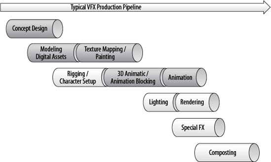
Figure 1.1. Typical workflow stages of a visual effects (VFX) production pipeline; the darker sections indicate where Mudbox could be used
Mudbox can be used as a stand-alone application, enabling a user to start with one of the provided primitives and end up with a final render of a sculpture. However, most artists use it in a production pipeline in which inputs flow into the program, and outputs flow out to 3D and 2D applications. The data flowchart (Figure 1.2) demonstrates this sequence.
The starting point of Mudbox is a model. This model can be one of the provided Mudbox starter meshes, or a primitive or base mesh model you generate in a 3D program such as Maya, or a scan from 3D digital scanner. You can also import 2D images to use as textures, stamps, or stencils.
In Mudbox, you pose, sculpt, and detail the geometry of the model, and then use the 3D painting capabilities to texture and paint it. Mudbox includes some rendering capabilities—such as lighting based on high dynamic range imaging (HDRI) and ambient occlusion (AO)—which give you a good idea of what your model will look like when output to an external renderer.
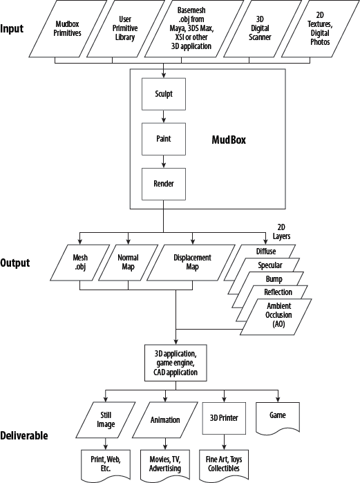
After you are finished with your model in Mudbox, you will output the following files:
A lower-subdivision-level version of your sculpted model, which has polygon counts that the intended 3D application or game engine can support. These models have the overall shape of your final sculpture but lack the detail. These are exported as
.objor.fbxfiles.Two-dimensional images, called normal and displacement maps, to wrap around the lower-resolution version of your model that you exported as an
.objor.fbxfile. These 2D images give the illusion of the detail you had on the high-subdivision-level, high-polygon-count sculpture but require significantly less computing resources to render and animate.Two-dimensional images of all the paint layers that you painted your sculpture with, to composite onto your final deliverable.
Before moving to the next stages, I recommend you take some time to go through the five one-minute movies that come with Mudbox. You can find them on the Welcome screen that comes up when you launch Mudbox. If you closed this screen, you can also access the movies through Help → Learning Movies, which brings up a Welcome screen for you to click on the movies. These movies will get you started with Mudbox by showing you how to navigate with a mouse or a tablet, and how to paint and pose.
I can't stress how important and indispensible a tablet is for digital sculpting and 3D painting in Mudbox. Even though it is possible to do the lessons with a mouse, it will be extremely tedious if not impossible to get good results. Tablets come with varying capabilities and sizes. Some come with a display that you can directly draw and sculpt on, others are wireless, and some have more sensitivity levels. I use the medium-size Intuos4 tablet from Wacom.
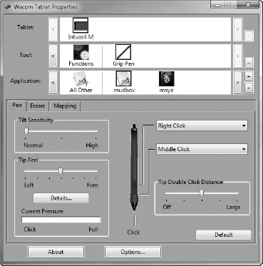
I will go through how to set up and optimize settings for the tablet in Mudbox, but for now, just make sure your tablet stylus buttons are set to Middle Click for the front button and Right Click for the back button. To do this for Wacom tablets, make sure Mudbox is running, open the Wacom control panel (Figure 1.3), and follow these steps:
Near the top of the dialog box, click the plus sign to the right of Application.
Click Mudbox and then click OK. Notice that Mudbox is added to your application list and has a highlight around it, indicating that it is selected.
Make sure you are on the Pen tab. Click the drop-down menu that is mapped to the back button and choose Clicks → Right Click.
Click the drop-down menu for the front button on the stylus and choose Clicks → Middle Click.
Close the Wacom control panel.
If you are using a tablet, henceforth in this book, substitute a tap of the stylus for clicking the left button of the mouse, a tap of the forward button on the stylus for clicking the middle button of the mouse, and a tap of the back button on the stylus for clicking the right button on the mouse. Tap the stylus and drag on the surface of the tablet to substitute left-clicking and dragging the mouse.
In the rest of this chapter, you will go through the Mudbox pipeline to produce a realistic-looking egg.
A base mesh, or cage as it is sometimes referred to, is a 3D polygonal object that has been modeled in a 3D application and saved or exported as an .obj file.
To paint this model, we need to unwrap it into 2D before we bring it into Mudbox. If an object has been unwrapped and has UV coordinates associated with it, the UV information will be included in the .obj or .fbx file. Chapters 3, 4, 5, and 6 explain in depth what UVs are and how to generate them. For the examples in this chapter, where needed, the UVs are done and provided for you.
To load your base mesh into Mudbox, follow these steps:
Now that the base mesh is in Mudbox, you can look at it from any angle and zoom in and out to enlarge areas you will be working on in depth. When you are performing the following actions, you are not moving the object but rather the camera through which you are looking at the object. This is similar to framing, let's say, a statue in a museum, in the viewport of a point-and-shoot digital camera. You point your camera at the statue, and walk around it while using the zoom features to perfectly frame the feature you wish to capture in the camera's display viewport before taking the snapshot. Becoming comfortable with navigating the camera is critical to your workflow. Practice as long as you need to, until you are comfortable getting to the area you need to manipulate with minimal steps.
To work with the camera, follow these steps:
Press and hold down Alt and tap and drag your stylus tip on the tablet to tumble or spin the model; with a mouse, hold Alt while left-clicking and dragging.
To pan, press and hold down the Alt key and the forward button on your stylus, and hover the stylus over the tablet without touching it. The equivalent movement with a mouse is holding Alt while middle-clicking and dragging.
To zoom in and out of your model, press and hold down the Alt key and the back button on the stylus, and hover the stylus over the tablet without touching it. The equivalent movement with a mouse is holding Alt while right-clicking and dragging.
Press W to show or hide the wireframe on the model.
To focus on a specific area, point to it with the cursor and press the F key on your keyboard. Now tumble around as you did in step 1, as you can see the center of your rotation is now your focus point. This is a handy way to set the focus on your work area.
To see all of your model, press the A key.
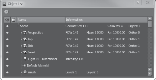
From the Window menu, choose Object List (see Figure 1.4). The Object List shows you all the cameras, lights, objects, and materials in your scene.
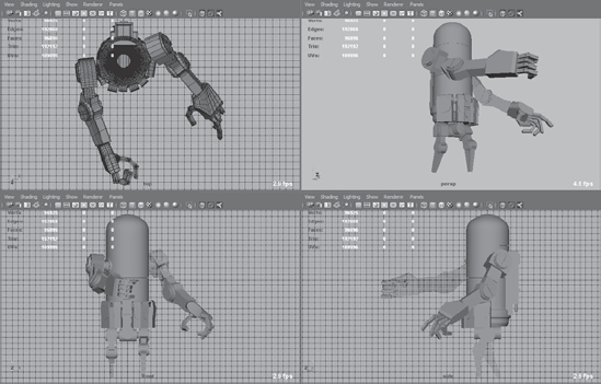
Notice that you have four default cameras already available to you. If you use other 3D applications, you are usually looking at your object in four views (Figure 1.5). In Mudbox, you work in only one viewport. You can switch from one camera to another by right-clicking the appropriate camera with your mouse, or by pressing the back button on your stylus, and selecting Look Through from the drop-down menu. Look through all four cameras.
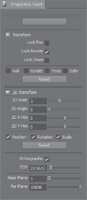
Notice that as you select a camera, the properties of that camera are displayed below the Object List in the Properties tray (Figure 1.6).
Look through the Front camera. Use the navigation methods I explained earlier to move around your model. Now look through the Top camera. Look through the Front camera again. You will notice that you are not looking at the model in the front view, but the view you actually left your model in. To get the camera to snap back to the front view, in the Transform properties of the camera, select the Roll, Rotate, Track, and Dolly check boxes and click the Reset button (Figure 1.7). This reverts your model to the original front view.
Note that there are three lock options in the Transform properties of your camera: Lock Pan, Lock Rotate, and Lock Zoom. When you want to restrict any of the three transform capabilities of the camera either for convenience or because you have attained a desirable camera view state, you can lock the change in the camera position, orientation, and magnification by choosing one, two, or three of these options. Note that the Front, Side, and Top cameras have the Orthographic option selected by default, which means they do not show your objects with any perspective depth. Experiment by navigating around your model with these options to get an idea of how they work.

You have now navigated the 3D view with your tablet or mouse and the Alt key. The introductory movies in the Welcome screen give an excellent demonstration on how to do this. Table 1.1 is a cheat sheet to get you started, but this will become second nature for you after your first few sessions.
Table 1.1. Navigating with the Mouse and Tablet
ACTION | TABLET | MOUSE |
|---|---|---|
Tumble or spin | Alt + click down and drag stylus | Alt + left-click and drag mouse |
Pan or track | Alt + forward button and drag stylus | Alt + middle-click and drag mouse |
Dolly or zoom | Alt + back button and drag stylus | Alt + right-click and drag mouse |
| ||
Now that you know how to navigate the camera around your model, you will go through the entire Mudbox pipeline with a simple example of an egg. You will start with a primitive sphere and then shape it into an egg. You'll then sculpt the eggshell and paint it. Finally, you'll output displacement, normal, and texture maps to Maya and use mental ray to do a final render of the model.
You can follow these instructions step by step, or watch the movies of this project in the Chapter 1videos folder of the DVD. These videos are divided as follows, based on the four stages in the chapter:
To block in the egg shape, follow these steps:
Start Mudbox and click the Close button in the bottom-right corner of the Welcome screen.
Choose Create → Mesh → Sphere.
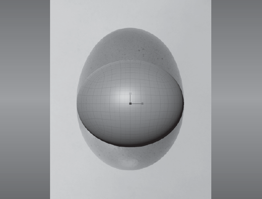
Press W to show the wireframe, if it's not showing. Tumble around the sphere and observe the polygons that compose the sphere. Notice that there are at most four edges coming out of each vertex, except for eight vertices that have only three edges. Also, notice that all of the polygons composing the sphere are four-sided quadrilaterals (or quads). Chapter 3 covers why this type of geometry layout is ideal.
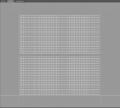
Click the UV View tab on the top left of your screen to see the UVs of the sphere. Notice that the sphere is unwrapped perfectly into quads with no overlapping lines. Also note that the UVs fit perfectly into the first quadrant square (Figure 1.8). When you are finished looking at the UV view, click the 3D View tab.
The two sections on the right and bottom of the screen that contain tools and trays are referred to as the East and South Frame trays, respectively, even though they are not labeled as such. Click the Object List tab at the top of the East Frame tray. Notice that there are four cameras created for you already: Perspective, Top, Side, and Front. You also have a default Directional Light, a default Material, and the Sphere mesh geometry. Right-click the Sphere object in the list, choose Rename Object, and type
egg.Click the plus sign next to the mesh you just renamed to see the first-level mesh. Move your mouse between the Name and Information columns in the Object List, and resize the Name column by dragging the divider bar to the left so you see more information on the mesh. Notice that the Sphere primitive has two subdivision levels labeled level 0 and level 1. Notice that the first subdivision level, level 0, has 384 polygons, and level 1 has 1,536. As you add layers, they will be listed under the mesh name. The Information column beside the Name column also gives you more details on the different objects in the scene.
Right-click the Front camera and select Look Through. Notice that the Properties tray under the Object List has the properties of the camera. Make sure the Lock Rotate check box is selected. This prevents you from accidentally rotating the camera. If you accidentally change the camera view, select the Roll, Rotate, Track, and Dolly check boxes and click the Reset button to reset the camera to its original view.
Click the plus sign next to the Front camera and click ImagePlane. Notice that the ImagePlane properties replace the camera properties in the Properties tray underneath the Object List. Click the drop-down arrows next to Advanced and Transformation properties to open them. Click Import and navigate to the
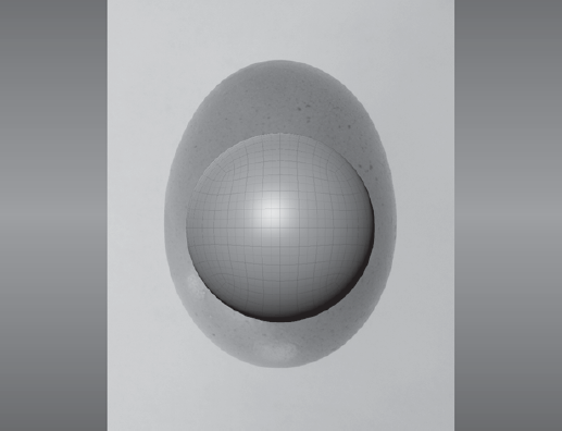
Chapter 1egg
eference and image plane files
folder and load theegg_side.jpgimage. It will load in front of your ball and might take up most of the 3D view.In the Advanced section of the ImagePlane Properties tray, change the Depth to 100. Now you will see the sphere in front of the egg.
If you do not see the top and bottom of the egg in the 3D viewport, click in the Scale text box in the Transformation section of the ImagePlane Properties tray, and type 1 or 0.8 or 0.6 (80 percent or 60 percent resizing of the image) until you can see both the top and bottom of the egg in the 3D viewport. Notice that you can also rotate and translate the image plane, but for our example, this is good enough.
Now use Alt + middle mouse button, or Alt + forward button on the stylus, to position your egg so the leftmost and rightmost edges of the sphere line up with the leftmost and rightmost edges of the egg in the picture (Figure 1.9). Also line up the center as best as you can.
In the Object List, right-click the Side camera and select Look Through. You will no longer see the image plane, just the sphere. This is because you are now viewing the sphere through the Side camera that does not have an image plane yet.
Click the Image Browser tab at the top left of your Mudbox window.

Navigate to the
Chapter 1egg
eference and image plane files
folder on the DVD.Click the
egg - high frequency detail.jpgthumbnail in the left Image Thumbnail tray and press Alt while clicking and dragging on the image to see the finer detail of the egg's surface. As you can see, it is not smooth. Note the roughness that shows up, especially in the white, shiny specular region. Also note the variation of oranges in the diffuse color and the reddish blemishes on the surface. Observing reference material is critical to the creation of art. Whether you are imitating, exaggerating, or distorting what you see, you really need to look at it and understand its nuances first. Click theegg_top.jpgthumbnail and notice that from the top, an egg looks circular. Finally, click theegg_side.jpgthumbnail.
Click the 3D View tab in the top-left corner. Notice that the egg is set as the image plane and is in front of your sphere. Click the plus sign next to the Side camera and click ImagePlane. In the ImagePlane properties, click the drop-down arrows next to Advanced and Transformation properties to open them. Change the Depth to 100. Now you will see the sphere in front of the egg.
Click Scale and choose the same scale that you used for the front image plane, either 1, or 0.8, or 0.6.
Switch back to the Front camera by right-clicking it in the Object List and choosing Look Through, and select Lock Zoom in the camera's properties.


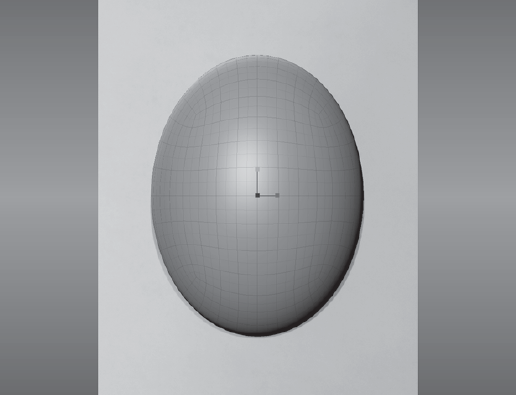
Click and drag the red square (x-axis) on the horizontal scale manipulator to widen the sphere so the edges line up with those of the egg. Align the sphere by pressing Alt + middle mouse button, or Alt + forward button on the stylus, to pan the camera and position your egg so the leftmost and rightmost edges of the sphere line up with the leftmost and rightmost edges of the egg in the picture (Figure 1.10).
Now click and drag the green square (y-axis) on the vertical scale manipulator to change the height of the sphere so the top and bottom edges of the sphere line up with those of the egg in the image plane. If needed, align the sphere by pressing Alt + middle mouse button, or Alt + forward button on the stylus, to position your egg so the top and bottom edges of the sphere line up with the top and bottom edges of the egg in the picture (Figure 1.11).
Switch to the Side camera by right-clicking it in the Object List and selecting Look Through.
Align the top and bottom of the sphere with the image plane by pressing Alt + middle mouse button, or Alt + forward button on the stylus. Click and drag the blue square (z-axis) on the horizontal scale manipulator to widen the sphere so the edges line up with those of the egg. Align the sphere by pressing Alt + middle mouse button, or Alt + forward button on the stylus, to position your egg so the leftmost and rightmost edges of the sphere line up with the leftmost and rightmost edges of the egg in the picture.
Right-click the Perspective camera in the Object List and select Look Through. Tumble the camera around your egg and examine your work. Next press the L key and click and drag your mouse, or tap and drag your stylus, to change the direction of your light.
Click the Material Presets tab in the South Frame tray and select the material (Gesso). You can identify a material's name by hovering your mouse over it; Gesso is one of the white materials. This changes your egg color to white. To see the name of a material, hover your cursor on top of it in the Material Presets tray and wait for a pop-up that gives you a larger thumbnail and the name of the material.
Save your work by choosing File → Save Scene As
egg_step_01.mud. You can see me going through the stages in this section in theChapter1-part1.movvideo in theChapter 1Videosfolder.
Suppose that this egg will be used in a commercial or movie clip, where it is impossible to use a real organic prop because eggs are brittle and delicate. In the storyboard, we see that we'll have a close-up shot requiring the details on the surface of the egg to be visible.
Now that you have the egg shape, you need to add the rough texture that you saw in the reference image. You can either continue from the previous lesson or load the scene file egg_step_01.mud from the Chapter 1eggegg_projectMudbox folder on the DVD.
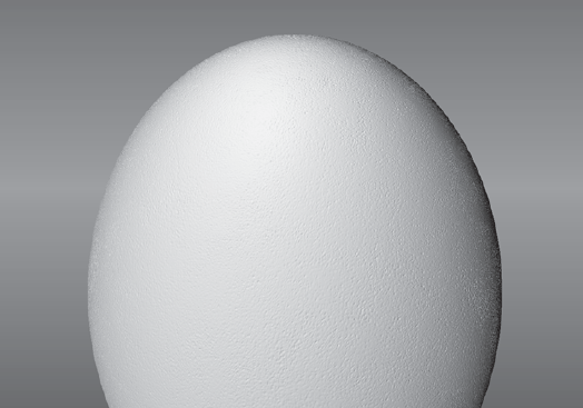
Press Pg Dn to go to subdivision level 0 on the egg. In the Object List, you can see that your egg has only 384 faces at level 0. Even though the egg looks smooth in the middle, you can see some faceting when you look at the edges of the egg. Faceting means you see big squares or polygons making up the surface instead of a smooth, polished surface. When we sculpt on a model, we are moving the vertices that make up the polygons. If we have only these few faces and we move the vertices at level 0, we will not be able to get the level of detail we want.
The lower levels of a mesh are great for blocking in the shape, but not for adding detail. If, for example, you want to make a character's chin longer or work on the overall shape of your model, use the lower subdivision levels. This is where you will get the best result for the least amount of manipulation.
One of the skills that you will need to develop to be an effective digital sculptor is knowing which subdivision level best suits the task at hand. Another skill is knowing the optimal amount of geometry needed to display the required detail. It is a constant struggle between what the software and hardware can handle versus the detail level your project demands. As I noted before, our egg has too few polygons for us to to get the result we want, so we need to subdivide it to get more subdivision levels.
Follow these steps to add subdivision levels to your model:
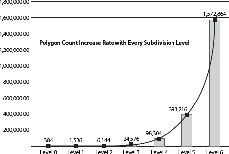
Press Pg Up to go back to subdivision level 1 at 1,536 polygons. Choose Mesh → Add New Subdivision Level. Notice that as you do this, status information about the new subdivision level appears at the top-right corner of the 3D view. It stays on for only a few seconds. If you missed it, don't worry, the same information is available to you if you click the plus sign next to the Egg mesh object in the Object List, and in the status line at the bottom-right of the Mudbox window. You can see that now you are at 6,144 polygons, which is four times the number of polygons you had. Every time you subdivide your model, you will end up with four times the number of polygons you had. At the lower levels, the number of polygons is not significantly greater than those of the previous level; however, as you get to higher subdivision levels, the numbers start going up significantly. For our simple egg, notice that as you get into level 6, you are already at 1.5 million polygons (Figure 1.12).
Press Shift+D to subdivide your model one more time. If you don't have the wireframe display on, press the W key to see the wireframe on the egg, and notice the new polygons that the new subdivision level has added. You are now at level 3, with 24,576 polygons. Also notice that a new line has been added to each of the levels under the Egg mesh object in the Object List.
To move up or down in levels, hover your cursor on the egg model, and press Pg Up or Pg Dn, respectively. To find what level you are on at any time, look at the status bar at the bottom right of your Mudbox window. The current level is listed as the Active level. You can also press Pg Up or Pg Dn and look at the information that pops up in the top-right corner of the 3D view. Subdivide your model up to level 6. If you have the wireframe on, you will notice that the lines show up as very dense on the surface, so turn off the wireframe by pressing the W key.
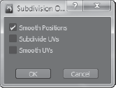
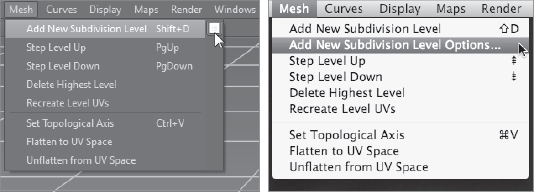
As the mesh is subdivided, notice that Mudbox creates a smooth-surfaced result. In our egg model, we do want that smooth subdivision result. However, if you are working on a model requiring creased, hard-surface edges (for example, the edges of a box), you need to subdivide your model with the Smooth Positions option off in the Mesh → Add New Subdivision Level Options dialog box (Figure 1.13).
To access the subdivision options, you need to click the options box next to the Add New Subdivision Level menu item (Figure 1.14). On the Mac, you need to select the Subdivision Level Options menu item.
Now that you have your egg of 1.5 million polygons, you will start adding the surface detail. But before you do that, you will add two sculpting layers. One layer is for the uniformly rough, high-frequency detail on the surface of the egg, as you saw in the reference picture egg - high frequency detail.jpg on the DVD. The other layer is for the nonuniform spots and bumps on the surface. The reason we do this in layers is so we can dial the detail of the sculpting layer up and down as needed. This will become clearer in the following steps. Sculpting in layers is a powerful capability you will learn to love because it will save you a lot of time during your work, specifically for exploring what if scenarios, undoing a whole bunch of sculpting in one swift step, and layering effects of surface detail. Follow these steps to add the two layers:
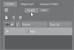
Click the Layers tab in the East Frame tray. Click the Sculpt button (Figure 1.15).
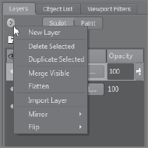
Click Pg Up until you are at subdivision level 6. Click the arrow under the Layers tab to open the Layers window menu and choose New Layer (Figure 1.16). Do this again to add another layer. Notice that you now have two sculpt layers in the Layers list.
Double-click sculpt layer 1, rename it
eggshell, and press Enter. Do the same to sculpt layer 2 and call itspots. You now have your two sculpting layers.
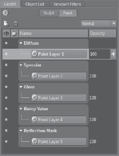
Notice the five columns in the Layers tray. The first column indicates visibility of the model and can be toggled on and off by clicking the small circle next to the name of the layer. A full circle indicates that the layer is visible, and an empty circle indicates that the layer is hidden. The second column is Lock, which allows you to lock that layer from being edited. The third column shows the subdivision level assigned to this particular layer; this column is just informational and cannot be manipulated. The fourth column is the name of the layer with an icon in front of it, and it can be changed. The fifth column is the opacity of the layer (Figure 1.17). Note that Figure 1.17 is just for reference of the user interface and does not indicate what your Layers tray should look like for this project.
The five columns in the Layer tray are as follows:
Visibility You can turn on the visibility of a layer by clicking the small circle in the Visibility column. If you use Photoshop, you are familiar with this because Photoshop uses the same method of showing and hiding layers.
Lock To lock a layer and disable editing on it, click on it in the Lock column. You will see an image of a closed padlock when a layer in the column is locked.
Level This column indicates the subdivision level assigned to this layer.
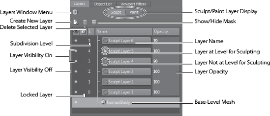
Name You have already seen how to rename a layer. The icon in front of the layer name denotes whether you can sculpt on that layer. Even if there is no lock on the layer, you might not be able to sculpt on it because you may not be at the subdivision level the layer was created in. A sculpt layer can be assigned to only one single subdivision level. You can have multiple layers that have the same subdivision level, but each layer is assigned one and only one subdivision level. For example, sculpt layers 4, 6, and 7 can all be of subdivision level 5. However, you can work only on subdivision level 5 in sculpt layers 4, 6, and 7. The way you assign a level to a layer is to be at the desired level before you make your first sculpting stroke on it. This could cause some frustration because you could be on a layer and not be able to sculpt on your model. If this happens, look at the layer to see whether there is a red circle with a line through it next to the layer name. If there is, you are at a different level than what this layer was set to. That's why you are not able to sculpt on it. To fix this, create a new layer for the level you are on, click on the base-level mesh in the Sculpt Layers tray, or press Pg Up or Pg Dn to get to the subdivision level to the left of the layer name.
Opacity You can either enter a numerical value or use the slider to show the opacity of your sculpt layer. This is useful for dialing up or dialing down the detail on a layer.
You are now going to sculpt the detail on the surface of the egg. This is a really simple example of sculpting, or rather surface detailing; you will do some more shape sculpting in Chapters 3, 5, and 6. Here are the steps:
Click on the
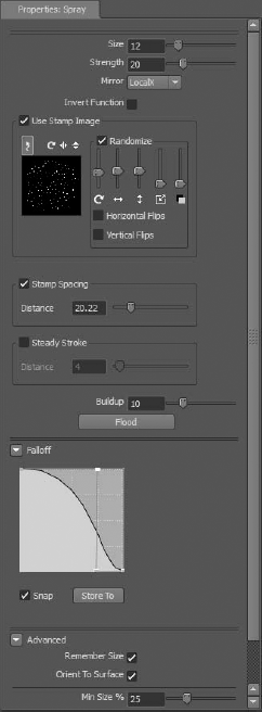
eggshelllayer in the Layers tray to select it.Click on the Sculpt Tools tray in the South Frame tray panel and choose the Spray tool. Notice that the Spray tool properties come up in the Properties window.
As you move your cursor onto the egg, you will notice a circle with a dot in the middle of it moving on the egg. This is your brush. The circle is the area you are affecting with your brush.
In the Falloff tray, choose Falloff 4 (the fifth one, because they start at 0). You will see the Falloff name pop up when you hover your cursor over it.
From the Stamp tray, look for and choose the
bw_dotsstamp (the 11th one). You will see the stamp name pop up when you hover your cursor on top of it. Notice as you choose the stamp that the Use Stamp Image check box gets selected in the Spray Tool properties.In the Spray Tool properties, click the arrow to open the advanced options (Figure 1.18) and select the Remember Size and Orient to Surface check boxes. The Remember Size check box sets your brush size to the size it was when you used the tool last. Orient to Surface makes your brush wrap around the model.
While your cursor is on your model, press and hold the B key on your keyboard and drag. This changes the size of the circle and your brush. You will do this a lot to adjust the size of your brush.
While your cursor is on your model, press and hold the M key on your keyboard and drag. This shows you a line going up from the center of the circle. This is your brush strength, which determines how much the sculpt tool affects the surface. The longer the line from the center of the circle, the deeper an imprint your brush will make on the surface of your model. I recommend you start with a lower strength and dial it up as needed. Notice that you can enter numerical values for both Size and Strength of your tool in the Spray Tool properties (Figure 1.18).
For this lesson, let's type in the strength and size of your brush. Set Size to 14 and Strength to 2.
Click the Mirror drop-down and select Local X. Also select the Randomize, Horizontal Flips, and Vertical Flips check boxes.
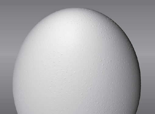
While holding down the Ctrl key, place your cursor on the top of the egg and then click and drag your mouse to start creating the eggshell pattern on the egg's surface. Zoom in to see the detail (Figure 1.19). You are holding down the Ctrl key so you sculpt inward, into the egg, instead of creating a relief off the surface. You can also sculpt without holding down the Ctrl key to add some relief and create even more variation to the surface. Cover the entire surface of the egg with this pattern, alternating between pressing down and not pressing down Ctrl. Rotate your egg to make sure you cover all of it.
To check that you have covered the entire surface of the egg with this pattern, hold down the l (light) key and click and drag the cursor on the surface. This moves the light and shows you more of the detail on the surface by changing the lights and shadows. You might see some anomalies as you are doing this, but don't worry, that's Mudbox rendering the details, and it will eventually catch up to display the correct detail. Notice that this detail is a little exaggerated, but that's by design, because you are going to dial it down by using the Opacity of the layer after you are finished sculpting.
A 6 appears next to the
eggshelllayer in the Layers tray, indicating that this layer is on subdivision layer 6 of the egg; the layer is at opacity level 100. Either type 0 or drag the opacity slider to 0 to hide theeggshelllayer. You are back to your smooth egg.Click the
spotslayer to select it.In the Spray tool properties, select Off from the Mirror drop-down list. Also deselect the Randomize, Horizontal Flips, and Vertical Flips check boxes.
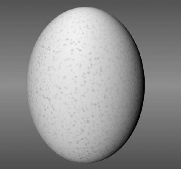
Change the Brush size to 50 and Strength to 2.5. Make short strokes on the surface by using the Ctrl key on and off to get some spots that poke out, and some that poke in. You want to have a very few of these, so go easy on the strokes. If you end up making a bad stroke, you can always use Ctrl+Z to undo your strokes. You should end up with an egg with some protruding and some indented spots (Figure 1.20).
Use the opacity sliders on your two layers to get the perfect look for your egg's surface. An opacity of 46 on the
spotslayer and 59 on theeggshelllayer looked appropriate for me. If yours doesn't look right, load the scene fileegg_step_02.mudfrom theChapter 1eggegg_projectMudboxfolder on the DVD to see an example of the results you are going for and try again (remember to dismiss the two dialog boxes that come up by pressing the OK button). When you are happy with your results, save your file asegg_step_02.mud. You can see me going through the stages in this section in theChapter1-part2.movvideo in theChapter 1Videosfolder.
The detail you have just sculpted onto the surface of the egg is called high-frequency detail. You will be using this to add fine detail such as wrinkles, cloth patterns, scratches, and dents to your sculptures. If you feel adventurous at this juncture, reload the egg_step_01.mud file and use some of the different sculpting tools to add other details to the surface. I will cover all of the tools in later chapters, but for now, just remember that if you press Ctrl, you depress the surface, and if you use a tool without pressing Ctrl, you add to the surface. Also try different stamps to get a feel for what they do.
If you have used Adobe Photoshop, Corel Painter, or any image-processing or compositing application that has paint layers, you understand the benefits of overlaying layers, placing them in a certain order, and fine-tuning their opacity to get amazingly realistic results. In most 3D productions, texture artists usually paint textures in layers and then composite them onto the model at render time so adjustments can be made to them on an individual level.
In this section, you will paint a base layer of paint on your egg, accent it with a second layer of paint, and then add red spots. Then you will use a variant of the side image plane file (where I have removed some of the specular highlights in Photoshop) as a stencil to project paint the exact color of the egg in the picture onto yours. You will then add some specular and gloss highlights to your image. Let's get started:
Either continue from the previous lesson or load the
egg_step_02.mudfile from theChapter 1eggegg_projectMudboxfolder from the DVD.In the Layers tray, click the Paint button to activate the Paint Layers tray (Figure 1.21). Please note that Figure 1.21 is a reference to explain paint layers and is not what you will see in the current project.
Click the Layers window drop-down menu and choose New Layer (Figure 1.22).
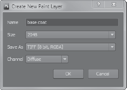
This brings up the Create New Paint Layer dialog box (Figure 1.23). Type
base coatas the name for your layer, choose 2048 as the size, and TIFF [8 Bit, RGBA] as the image format. The 8 bits give us 16.8 million colors, which will work for this scenario. This will be one of three diffuse layers. Diffuse is the base color we see, without highlights or shininess, just the base paint color.Add a total of three diffuse layers:
base coat(which you already created in the previous step),red spots, andprojection.Add another layer, call it
highlights, and choose Specular from the Channel drop-down menu. In this color image, the lighter colors will show up with specular highlights, and the darker areas will not shine at all. A specular map is a way to indicate the areas on your model you want to highlight because they are part of surfaces that have a more shiny, reflective property (for example, oily areas of the forehead).Finally, add a layer, call it
glossiness, and pick Gloss from the Channel menu. Like the specular image, this one's lighter colors represent areas that will appear glossy, and the darker areas will not. Areas that have high gloss values look wet, while areas with high specular values look shiny.Bring up the Object List and look through the Side camera. The image plane of the egg should still be in the background. Move the egg to the side by clicking the Translate tool in the Select/Move Tools tray, and clicking and dragging the red or green arrow on the move manipulator that appears in the 3D View. From the paint tools in the South Frame, click the Eyedropper tool and move the eyedropper icon onto the image of the egg to choose the base color of the egg. Do your best to pick the general color that does not have any highlights or shadows or pigmentation, somewhere in the middle of the egg.
Click the Airbrush tool and notice that in its properties, the color is the orange of your egg. In the Object List, look through the Perspective camera. Click the Airbrush tool again, and in its properties, turn Mirror on to Local X, and choose a brush Size of 60 and a Strength of 30. Click the Layers tab and make sure the
base coatlayer is selected.Paint your egg with the base orange color; make sure you color the entire egg evenly. You can check this by pressing Pg Dn to get to the lowest subdivision level of your model and looking at the UV view to see whether you missed any spots. If you see missing color in any areas of the unwrapped UV shell, you have missed those areas. Remember to press Pg Up to get back to the highest subdivision level before you continue.
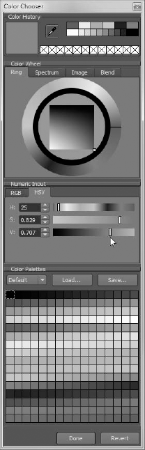
Click on the color in the Airbrush tool properties tray to open the Color Chooser. Choose a color that is a slightly lighter version of your current color by either using the color wheel, or expanding the Numeric Input section and choosing a color with slightly less Value by dragging the slider to the right (Figure 1.24).
In the Paint Layers tray, make sure the
base coatlayer is still selected. Choose thebw_dotsstamp from the Stamps tray if it's not the selected stamp for the Airbrush tool. Make sure Use Stamp Image and Randomize are selected. Also make sure that Horizontal Flips and Vertical Flips are selected. Move the five Randomize sliders to about the middle. This will ensure that you paint a very random pattern. To find out what each of these sliders does, check Chapter 2, "The Mudbox User Interface." Click Off from the Mirror drop-down list.Paint on the surface of the egg so you have an even pattern of dots all around, and you have some room to see the color you painted before, underneath or between the dots of your current paint work. Painting a surface with various subtle variations of the base color makes it look more realistic.
Click and select the
red spotslayer in the Paint Layers tray. Click the Airbrush tool again and click on its color property. Choose a dark reddish-brown. Of course, you can sample the exact color of spots off the egg image by using the Color Chooser technique you used previously.Type 150 in the Size text box of the Airbrush properties. Notice that if you drag the slider to the end, it caps out at 100, but you can type greater values in the text box. Paint random large red spots on the surface of the egg. Turn off the
base coatlayer to see your work. If you notice that you have too many red spots, use the Paint Erase tool in the Paint Tools tray to erase them. When you are satisfied with your random smattering of red dots, turn on thebase coatlayer and examine your work (Figure 1.25).Depending on the color distribution and your painting ability, you have probably ended up with a good rendition of the egg's surface color. To add an extra level of realism, you will use the actual egg image to project paint on the surface of the egg. To do this, I have taken the image of the egg shot from the side into Adobe Photoshop and used the Patch tool to remove some of the specular highlights in the photo.
Click the Image Browser tab and navigate to the
Chapter 1egg
eference and image plane files
folder on the DVD and look at theegg_no_specular.jpgimage. Ideally, you would not want to use.jpgimages in production to save textures or to paint textures from because.jpgis a lossy format. Lossy file formats use algorithms to average the color of pixels in order to compress an image so it's smaller in size when you save and load it. These images are called lossy because they lose some of the original color information in favor of reducing file size. Although lossy images might look OK at first glance, they often produce anomalies that create undesirable, blocky results in the picture when you zoom in or process them. In our example, it will not be an issue, but be aware of lossy compression for your projects and if at all possible use nonlossy, uncompressed image formats for textures. Click the Set Stencil button.
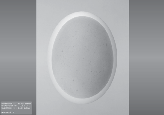
Click the 3D View tab and choose the Projection tool from the Paint Tools tray. Notice that there is a transparent image of your stencil overlaying your egg model (Figure 1.26). Also notice that there is some help in the bottom-left corner of the 3D view for manipulating the stencil. During this session, randomly press the S key and click and drag your stylus to rotate your stencil, and occasionally press the Q key to show and hide your stencil. You will not need to scale or move the stencil in this case, but note that you can scale and move the stencil with the S key and right and middle buttons of the mouse (or back and front buttons of your stylus).
Use your camera to roughly align the egg to the stencil image.
Tap and drag the cursor on the surface of the egg. You will project the image of the stencil onto the surface of the egg. You might want to choose Orient to Surface from the Advanced drop-down list in the Projection tool's properties.
Rotate the egg and project-paint the egg's surface. Notice that though this image looks pretty even in color, some areas are lighter than others because of the light illuminating the surface. Rotate your egg so you paint uniform color while also generating a random pattern of the surface. You can press the Q key to toggle the stencil image on and off to look at your work and erase areas that do not work for you. Remember that the stylus has sensitivity levels, so if you gently stroke on the tablet, the color variations will be more subtle on the surface.
Click on the Stencils tray in the South Frame and click Off to turn off the stencil.
When you are finished, examine your work. Look for color variations that are too strong, any edges of the projected egg's image that bleed onto your egg model, and repeating patterns that distort the believability of the texture. Watch the video
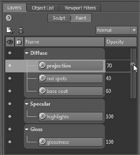
Chapter1-part3.movof this lesson in theChapter 1videosfolder of the DVD to see how I paint my model. When you are finished, compare your newly projection-painted layer with the previous three to see how quick and effective projecting from a picture is versus painting the image yourself. The good news here is that you can composite the two layers that you painted with the base coat and the red spots with the one that you projection-painted from the real picture of an egg—and play around with the opacity of the three paint layers you created—to get an even more perfect texture. To do this in the Layers tray, click on the opacity number and move the sliders up and down to see the results in real time in the 3D viewport. In my example, an opacity of 70, 40, and 60 worked best for the three diffuse paint layers ofprojection,red spots, andbase coat(Figure 1.27).Click the
highlightslayer in the Layers tray to select your specular layer. Choose the Airbrush tool, make sure that thebw_dotsis selected, and that Use Stamp Image, Randomize, Horizontal Flips, and Vertical Flips are also selected. Choose white or a light gray for your color. Turn off all other layers and paint a nice random pattern on the surface of your egg with a brush size that's about a quarter the size of the egg. Start with a weaker strength and dial it up until you get a nice specular pattern similar to that in the close-up reference pictureegg-high frequency detail.jpgin theChapter 1egg eference and image plane filesfolder of the DVD. These are the areas you want to show up when a light is shining on the surface.Specular layers enable you to specify parts of your texture that are shinier than others and reflect more light, creating specular highlights. If you have some matte paint chipped off a metal surface, for example, you might want to paint the metal surfaces with a specular map so that when light shines on that surface, the metal parts show up shiny while the matte paint does not.
Choose the Paint Brush tool from the Paint Tools tray, and click on the
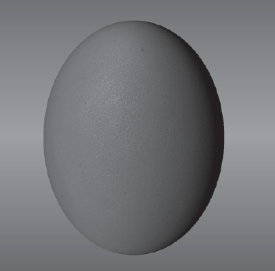
glossinesslayer in your Paint Layers tray. Make sure all your paint layers are visible by clicking the circles so they are filled in the Visibility column. Paint on your egg to make some areas look a bit glossier. On these areas, the egg might have a little bit of "sweat" from being taken out of a cold refrigerator, or have some egg white dripped on it from a hand that has cracked another egg. Again you can dial in the glossiness with the opacity slider of theglossinesspaint layer.You are now done with your egg model (Figure 1.28). You have the eggshell texture sculpted onto the surface of the model, and have painted on a texture that looks like the reference image.
Turn on the visibility of all the sculpt and paint layers, and work with their opacity to get as close to the look of the egg in the picture as possible.
Save your work as
egg_step_03.mud. When you save your work, Mudbox automatically creates a folder and saves all of your paint layers as individual files in that folder. You can see me going through the stages in this section in theChapter1-part3.movvideo in theChapter 1Videosfolder.In the Image Browser, navigate to the folder where you saved your file and click the
egg_step_03-filesfolder. You will see all of your paint layers. These are separate images that can be manipulated individually or composited in Adobe Photoshop or your favorite image-editing application.

Next you will create a mock-up of what your final render will look like.
In most 3D applications, you set up your scene, and your materials, textures, and lights, and then that information is taken into a renderer that outputs the results in the desired photorealistic or stylistic image. This can take a while, depending on complexity; every time a change is made, you need to re-render and wait.
The really good news is that all rendering happens in real time in Mudbox. Whenever you make any changes, whether they are sculpting, material assignment, texturing, or lighting, all the results are displayed as you are making the changes.
You also have some viewport filters that add additional effects to the 3D view, such as Ambient Occlusion and Depth of Field. I will go into detail about what these various viewport filters do, but for now, you will just use the Depth of Field for your egg. Depth of Field simulates a camera effect; some parts of the picture appear blurry or out of focus, while other parts appear sharp and in focus. This is a good method to draw the viewers' attention to the important parts of the image and use the blurry areas to create interesting gradations in the foreground or background. To add a Viewport Filter follow these steps:
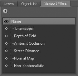
Click the Viewport Filters tab in the East Frame (Figure 1.29). Turn on the visibility of the Depth of Field layer, and click on the layer name so the Depth of Field properties come up.
Make sure the grid is on by clicking the Display menu item and selecting the Grid check box. Move the Blur Amount slider until you get a slight blur around the edge of the egg. If you get too intense of a blur, move the slider slightly and then double-click the slider handle; this limits the range of the slider. A value of about 0.001 should be good. Move the Focus Distance slider and notice how the focus shifts on the egg and the grid. Move the slider until the front or top-front part of the egg is in focus.
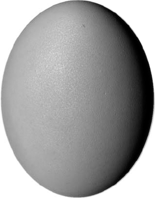
Now move the Depth of Field slider to get a nice soft edge on the egg. You can find detailed descriptions of these three sliders and what they do in the UI tour in Chapter 2. You might want to experiment with some of the other viewport filters to get an idea of what they do. Don't worry if you mess things up; you can always turn off the filters by clicking the eye icon to the left of the filter. By using a combination of viewport filters, I got the results shown in Figure 1.30.
In earlier versions of Mudbox, you would have had to take a snapshot of the screen to export your image by using Print Screen or a third-party utility such as TechSmith Snagit, but since Mudbox 2010, this deficiency is not only addressed but addressed with an extremely powerful feature. Not only can you now save the screen by choosing Render → Save Screen Image, but you can also save it in whatever image size you like. This is really useful if you want to save your image in sizes for posters or billboards. Save your image using your screen size by clicking the Use Screen Size button, or type in any size you would like in either the Width or Height text boxes. When you are finished, turn off the Depth of Field by clicking the eye icon next to it in the Viewport Filters tray. I have saved a copy of the screen for you in
.psdformat calledMudbox Render.psdin theChapter 1eggfolder of the DVD. When you are finished, turn off all the viewport filters.
You now have everything you need from your Mudbox session. It's time to export all the assets to be used in external applications.
Let's start by exporting the geometry. This is the wireframe mesh of the egg at the various subdivision levels (0 to 6). Although you can export all these levels individually, you will extract only levels 0 and 6.
Low-resolution geometry is used in scenarios where the geometry must conform to computational compromises—for example, in animation in a busy scene or as an asset in a fast-moving game. The less geometry, the faster the model can be manipulated in an animation or real-time game engine. There are great advancements in technology to fake the display of the high-resolution work on the low-resolution geometry in animation and game pipelines. These are done through normal and displacement maps. These are computationally less-demanding methods of displaying detailed light interaction and surface detail using low-resolution geometry.
Higher-level geometry is in most cases unusable for animation and games. Even with processing power doubling every year and a half with multiple cores, parallel processing grids, and graphics processing unit (GPU) advances, churning 1.5 million polygons for a simple egg is an impossible luxury. Instead, this level of geometry would be useful in these situations:
A high-resolution render of a still image in which the detail is critical—for example, if our egg was the subject of a billboard advertisement or a product shot for a glossy brochure. This high-resolution mesh can be imported into renderers that can handle this level of geometric complexity, such as Keyshot by Luxion.
Geometry that needs to be imported into other digital sculpting applications, such as ZBrush by Pixologic, for further manipulation in a production pipeline. Most production pipelines use multiple applications that complement each other, or sometimes even do the same thing because of various in-house artists' expertise. But in most cases, the final output from whatever application your high-resolution model is exported to will still eventually be a normal or displacement map.
To export the two levels of geometry:
Load the
egg_step_03.mudfile from theChapter 1eggegg_projectMudboxfolder on the DVD, or continue working from your previous session.In the 3D view, hover your cursor on the egg model, and press Pg Dn until you are at level 0 of detail. Tumble around the egg. Notice that even though you are at the lowest level of geometry, your surface detail on the texture still shows up. The only features of the egg that might not look right are the edges that look like straight lines. Press the W key to see the wireframe.
Click the Objects icon in the Select/Move Tools tray in the South Frame.

Choose File → Export Selection. Save your file in a work folder you create for your project as
egg_model_Level_0.objin the.objfile format.The
.objfile format is a simple data-format that represents 3D data most commonly used for importing and exporting geometry. It contains the position of each vertex in a very specific order, the UV texture coordinate associated with a vertex, the normal at each vertex, and the faces that make up the polygons. It was developed by Wavefront Technologies and has been adopted by most 3D graphics application vendors as an import/export format because of its open architecture. As mentioned,.objfiles contain not only the geometry information but the UV data as well.Press W to turn off the grid, and press Pg Up until you get to subdivision level 6.
Click the Objects icon in the Select/Move Tools tray in the South Frame and click the egg to select it.
Choose File → Export Selection and save the model as
egg_model_level_6.objinto the work folder for your project.
Note the difference in the file sizes of 182MB for the high-resolution .obj file versus 36KB for the low-resolution .obj file. We see a difference in scale of 3,000 from the smaller sized file to the bigger.
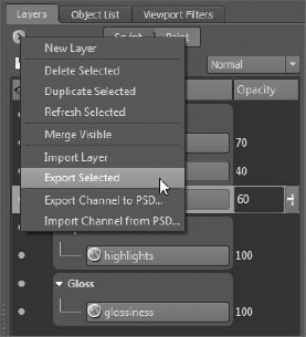
Exporting the texture maps is already done for us in Mudbox. Whenever you save a Mudbox file that you have created paint layers for, Mudbox automatically creates a folder with the filename and places each layer in it as an individual file in the format and size you specified when you created the paint layer. You can also save or export individual layers while you are working, before you save the Mudbox file, by clicking the Layers window drop-down menu in the Layers tray and then choosing Export Selected (Figure 1.31). You need to do this for each layer you want to export.
For our example, the texture maps are in the egg_step_03-files folder. They are all .tif files because that's what we chose as our export format when we created our layer. Most image formats have either three or four channels: red, green, blue, and alpha. The alpha channel is used as an opacity channel. If a pixel has a value of 0 percent (or black) in its alpha channel, it is fully transparent, and if it has a value of 100 percent in the alpha channel, it is fully opaque.
Mudbox has support for multiple image formats such as Targa (.tga), TIFF (.tif), Portable Network Graphics (.png), and OpenEXR. Chapter 2 covers these formats in depth.
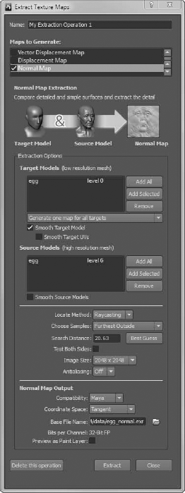
To export the normal map, make sure you are at subdivision level 6 of your model and then follow these steps:
Choose Maps → Extract Texture Maps → New Operation.
In the Extract Texture Maps dialog box (Figure 1.32), select Normal Map. Make sure your settings match those in Figure 1.32. I will discuss these settings in more depth in later chapters.
If it's not already populated for you, in the Extraction Options section, make sure the egg at level 0 is selected in the Target Models (Low Resolution Mesh) text box by clicking the Add All button. This is the low-resolution mesh onto which you will project the normal map.
In the Source Models section, also make sure
eggis selected again, but at level 6. This will take into consideration the highest subdivision level from which to generate the normal map. Again this should be populated for you; if not, click the Add All button to the left of the Source Models section.For the Locate Method, choose Raycasting, and for the Choose Samples option, select Closest to Target Model. For the Search Distance option, type 20.63 or use the result from clicking the adjacent Best Guess button. Choose an Image Size of 2048 × 2048 to match our texture maps. The bigger the size you choose for these maps, the finer the projected detail will be in your final destination application.
Click the Maya option in the Compatibility drop-down list.
7. Click the folder icon

Click the Extract button to extract the normal map. The Map Extraction Results dialog box appears, your normal map is generated, and a new dialog box comes up letting you know whether your normal map extracts without errors. You are finished extracting the normal map.
To export the displacement map, make sure you are at subdivision level 6 of your model and then follow these steps:
Choose Maps → Extract Texture Maps → My Extraction Operation 1.
In the Extract Texture Maps dialog box (Figure 1.33), select Displacement Map. Note that the Normal Map check box is also selected; leave it selected because it has all the settings from our prior normal map generation steps. The map generation settings are saved with the scene, and you can have multiple sessions with different settings saved under one scene. Make sure your settings match those in Figure 1.33. I will discuss these settings in depth in later chapters.
In the Extraction Options, make sure
eggis selected. This is the low-resolution mesh onto which the normal map is projected.In the Source Models section, make sure
eggis selected. This takes into consideration the highest-subdivision level from which to generate the normal map.For Choose Samples, select Closest to Target Model. The Search Distance of 20.63 is fine. To find out what Choose Samples does, hover your mouse on Closest to Target Model, and pop-up help will detail the difference in diagrams. I will go in depth into the different options in later chapters, but for now use the default of Closest to Target Model. Choose an Image Size of 2048 × 2048 to match our texture maps.
Click the folder icon next to Base File Name and type
egg_displacementas the filename. Select OpenEXR [32 Bit Floating Point, RGBA] as the file format and click Save. Make sure you choose RGBA and not the Black & White OpenEXR file format. Note that this does not generate the displacement map; it just sets the name.Make sure the Preview as Bump Layer check box is not selected.
Click the Extract button to extract the displacement map. The Map Extraction Results dialog box appears, your displacement map generates, and a dialog box appears to let you know whether your displacement map extracts without errors. You are finished extracting the displacement map.
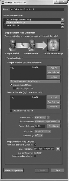
Note that you can extract both the normal and displacement maps in one step by selecting both of the check boxes in the Extract Texture Maps dialog box.
You are at the final stage of our pipeline in this chapter. After you have your model and your texture, normal, and displacement maps, you have everything you need to render your model for its destination. You can input these components into animation, rendering 3D printing, or game engine applications to use your model for its final purpose.
In this section, you will transfer your files into Maya 2011 and render an image. I will cover other applications in later chapters. The steps might be different, but the concepts and workflow are the same. If you have access to Maya 2011, follow the steps, or look at the rendered images in the Chapter 1eggegg_projectimages folder from the DVD, or watch the step-by-step movie on the DVD.
Copy
Chapter 1eggegg_projectand all of its subfolders to your hard disk and remember the location.Start Maya 2011 and choose File → Project → Set.
Navigate to the
egg_projectfile on your hard disk and click OK.A Maya project is a folder structure that Maya creates to organize all of your files for the project you are working on. Our exported
.objfiles are in theegg_projectdatafolder. Our texture, normal, and displacement maps are in theegg_projectsourceimagesfolder. TheMaya.mascenes of what we are working on are in theegg_projectscenesfolder. We also have a Mudbox folder that I manually created to store all of our Mudbox files.Choose File → Import.
If you are not automatically in the
egg_projectdatafolder, navigate to it and clickegg_model_level_0.obj. Then click the Import button to load it.Make sure you are in the perspective view by choosing Panels → Perspective → Persp in the Panel menu (Figure 1.34). Make sure this panel is the only one open by pressing the spacebar.
Select the egg model by clicking it. Press 6 to activate hardware rendering, and then press 3 to activate Maya's Smooth Mesh Preview mode. Notice that the jagged edges of our model are now nice and smooth. Even at 384 faces, we have a nice-looking model. This model will render smooth in mental ray without our having to subdivide it, or use the smooth operator on it to generate a smoother version of the model.
Choose Window → Settings/Preferences → Plug-in Manager.
Make sure that the Loaded and Auto Load check boxes are selected next to Mayatomr and OpenEXRLoader.mll.

Click the Quality tab. In the Quality Presets drop-down list, click Production: Fine Trace. This automatically sets the output quality to the best setting while compromising render time. Because we are rendering only one image, a longer render time is tolerable. Close the Render Settings dialog box by clicking the Close button at the bottom.
Choose Window → Rendering Editors → Hypershade.
Click Blinn to create a new Blinn shader.
Make sure that the egg is selected by clicking it. Right-click the Blinn node and, from the marking menu that comes up, select Assign Material to Selection.
Double-click the Blinn shader to open its attributes in the Attribute Editor (Figure 1.5).


This opens the file node attributes.
Click the folder icon next to Image Name and click the
egg_texture_comp_8_2K.tiffile. This is a composite of the three texture files we created in Mudbox (Figure 1.36).I have loaded the three individual paint layers in Photoshop, composited them into a flattened image, and saved it as an 8-bit
.tiffile. To see what this looks like, open thefile Chapter 1eggegg_projectsourceimagesegg_texture_comp_8_2K.psdin Photoshop. And look at the layers and their opacity.You should now see our texture applied to the egg (Figure 1.37).

I have set up a scene with three-point lighting that you can load and render. Choose File → Open Scene and click the
egg_texture.mafile in theChapter 1eggegg_projectscenesfolder on the DVD and click the Render button. Some things I have done in this setup besides adding and positioning three spotlights and a camera are adjusting the specular highlight of the Blinn shader, and modifying the Background color of the camera to a dark gray. Experiment by looking at the egg from different angles with different specular settings.Select the egg and choose Window → UV Texture Editor. Notice that the texture is applied to the UVs of the egg just as it was in Mudbox.
Close the UV Texture Editor and choose Window → Rendering Editors → Hypershade.
In Hypershade, right-click the Blinn shader you created and choose Graph Network from the marking menu. You will now add the displacement map.


Double-click the displacement shader to open its attributes in the Maya window.


This opens up the file node attributes (Figure 1.39).
Click the folder icon next to Image Name and click the
egg_displacement_32_2K.exrfile that we created in Mudbox. Your shader network should look like Figure 1.40.Render your image and notice that the displacement map applied to your image is the high-frequency detail sculpting we did in Mudbox. See Figure 1.41.
Next, you will create a shader for the normal map. In Hypershade, create a new Blinn node.
Make sure that the egg is selected by clicking it in the Maya Perspective viewport, and right-click on the Blinn node. From the marking menu that comes up, select Assign Material to Selection. That should make the egg look gray.

Double-click on the Bump2d shader to open its attributes in the Maya window.


This opens the file node attributes.
Click the folder icon next to Image Name and click
egg_normal_32_2K.exrfile (Figure 1.42). This is the normal map we created in Mudbox.Your shader network should look like Figure 1.43.
Render your image and notice that the relief of your high-frequency detail on the surface of the egg is greatly exaggerated (Figure 1.44). That's because you need to change one more setting to let Maya know that this is in fact a normal map and not a bump map.
In Hypershade, double-click the Bump2d node. This brings up the attributes for the node. In the Use As drop-down, select Tangent Space Normals and render your image (Figure 1.45).
Render your image and notice that you have the normal map applied to your model.
The true value of normal maps and their importance to the production pipelines can be demonstrated when we use Maya's ability to render normal maps to give you a real-time preview of the high-frequency detail that you sculpted in Mudbox that resulted in over 1.5 million polygons to display in real time on our 384-polygon model in Maya.
In the Perspective panel, choose Shading → Wireframe on Shaded and note that we still have our simple 384-poly egg model. Choose Shading → Hardware Texturing. This will not do anything to the display until the next step.
Choose Renderer → High Quality Rendering. You will now see the high-frequency detail appear on the surface of the egg. You can tumble around the egg to see all the details in real time. There is an anomaly that appears at the edges of the UVs on the egg that you can easily fix in the next step (Figure 1.46).
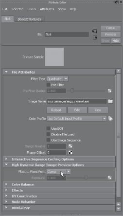
In Hypershade, double-click the file node. This brings up the attributes for the file node.
In the file node attributes, expand the High Dynamic Range Image Preview Options section. In the Float to Fixed Point attribute, click Clamp. This fixes the UV edge issue, and now you are previewing the relief on the surface of your egg in real time using the normal map (Figure 1.47). You can see me going through the stages in this section in the
Chapter1-part4.movvideo in theChapter 1Videosfolder.
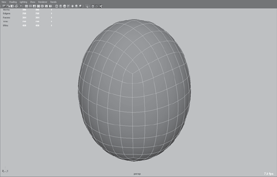
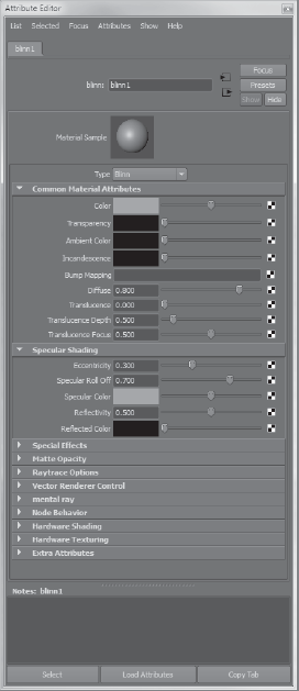
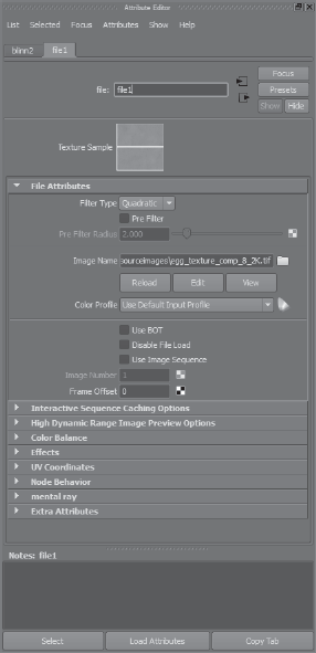
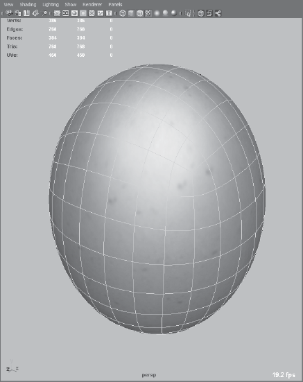
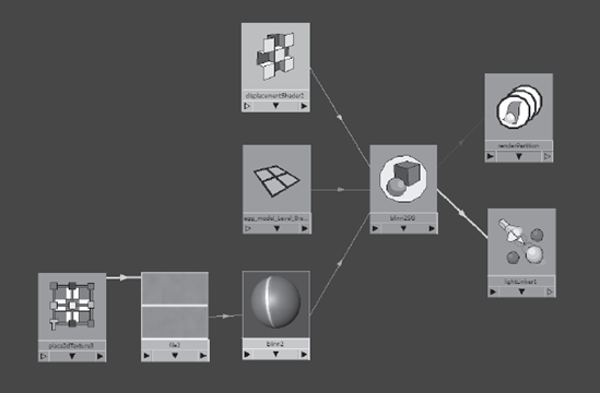
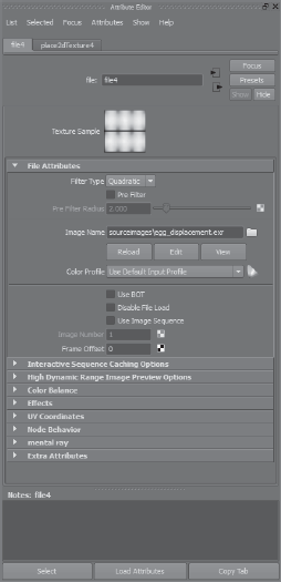

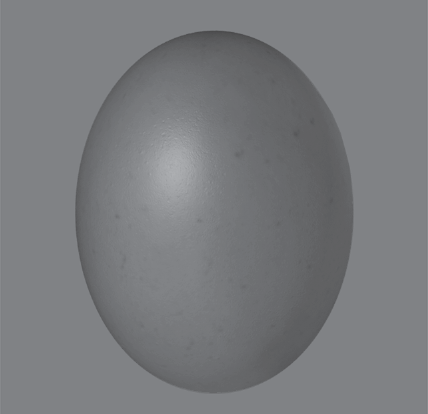

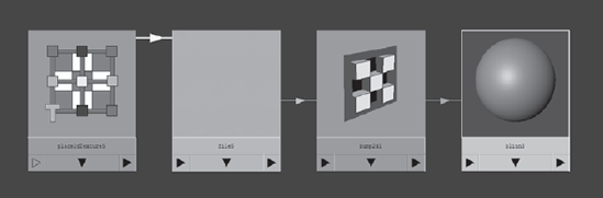

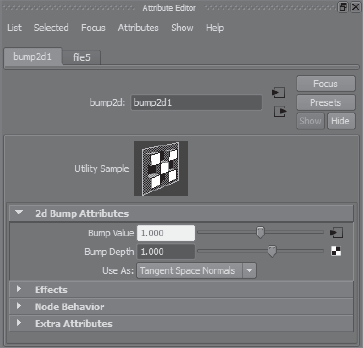
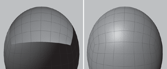
Figure 1.46. The high dynamic range image preview with Float to Fixed Point set to Linear (default) versus Float
I have included a finished version of the normal mapping section on the DVD called egg_normal.ma in the Chapter 1eggegg_projectscenes folder. Try adding the texture map to the Blinn node to see a fully textured normal mapped version of your egg, or open the egg_normal_texture.ma file from the Chapter 1eggegg_projectscenes folder to see your egg texture and high-frequency detail in real time. You can see the real power and benefit of normal maps here, where you have a very low-polygon egg that can easily be manipulated in games and movies, and yet be able to display high-frequency detail on its surface that reacts to light with minimal cost in processing power.
As I mentioned at the beginning of the chapter, this is the most important chapter in the book. Everything you will do from this point forward is expanding on the concepts you worked on here. Go through the steps, watch the videos, or load the finished files from the DVD to make sure you have a good comprehension of all the stages in this chapter.
You started out with a Mudbox primitive sphere. You learned how to move around your model by manipulating the camera view in Mudbox. Then you proceeded to block in the shape of the egg, subdivide it, and sculpt layers of high-frequency detail. You painted the model with our best approximation of what an egg surface would look like, in addition to projection-painting it with the surface of an actual egg in a digital photo. You used Mudbox's real-time preview to see what your model looked like and proceeded to export all the components out of Mudbox. You imported the geometry, texture, normal map, and displacement map files into Maya to output the final results of your work.
Hopefully, this chapter has set a good stage of the Mudbox production pipeline for you to build on in the chapters that follow.