
This chapter provides a reference or orientation of the Mudbox user interface (UI). I will cover the Mudbox interface, identify the different sections you see on the screen workspace, and outline the functions of the tools.
When you work with any program, you will initially focus on areas that are particular to the project at hand, as you did in Chapter 1, "Getting Your Feet in the Mud: The Basics of the Mudbox Production Pipeline." In most cases, users develop a comfort zone of features in the application they are working with and then go on to explore the interface to find other software features that can streamline their workflow or enable them to explore new areas of creativity in their work. This chapter lists the components of the Mudbox interface and what they do from a definition level. You will learn more about the usability of the key features in other chapters of the book.
If you are working in Mudbox and see something interesting yet unfamiliar to you, this chapter is the place to look it up. I recommend that you initially read through this chapter to get your bearings, and then refer back to it when you need to know where things are or for information about a specific tool or a section of the screen.
This chapter includes the following topics:
Starting out with the Welcome screen
Navigating the main viewport
Exploring the East Frame window
Working with the South Frame tray
Performing map extraction
When Mudbox first launches, you are greeted with the Welcome screen (Figure 2.1). The Welcome screen also comes up when you choose the New Scene option from the File menu.
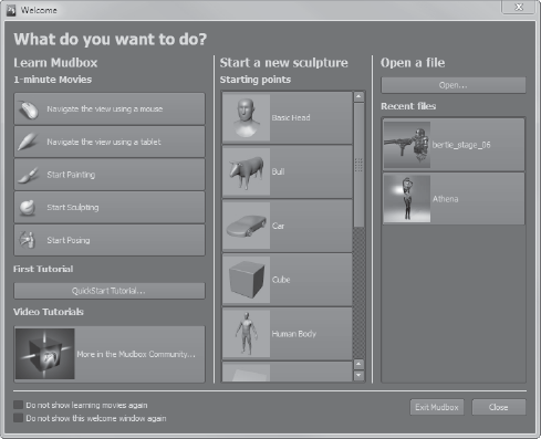
The main function of the Welcome screen is to jump-start your work session. If you are a beginner and need help with the basics, the first column of the Welcome screen displays five, one-minute tutorial movies to familiarize you with the essentials. These are as follows:
Navigate the View Using a Mouse
Navigate the View Using a Tablet
Start Painting
Start Sculpting
Start Posing
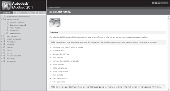
If you have not yet done so, I recommend that you run through all the tutorial movies at least once to familiarize yourself with the most basic and critical actions you will be performing throughout your sculpting session. If you have used Maya or other 3D applications, some of these functions will be familiar to you. After you run through the five basic tutorials, you can click the QuickStart Tutorial button to launch Mudbox's help, which covers 11 topics to get you further along (Figure 2.2). These topics are as follows:
Again, for a beginner, I recommend that you go through these sections at least once. You can access many more tutorials in the Mudbox Community by clicking the More in the Mudbox Community tab.
After you feel comfortable with the topics covered in the one-minute movies and the QuickStart tutorials, you can streamline your Welcome screen by clicking the Do Not Show Learning Movies Again check box at the bottom of the Welcome screen. You will learn how to revert back to showing the learning movies at the end of this section.
The next column of the Welcome screen give you the option to pick one of Mudbox's starting-point primitives, such as the Basic Head, Cube, or Sphere, to start your sculpting session. These primitives are provided for you to start from a basic generic shape and develop it into your personal creation. Although these shapes are good for practicing and doing some concept sculpts, you will soon discover their limitations and eventually develop your own library of primitives, or import models called base meshes from Maya or your favorite 3D modeling application. We will go into depth about the reasons that you might want to do this in Chapter 3, "Detail-Sculpting an Imported Model," Chapter 5, "Digital Sculpting Part I," and Chapter 6, "Digital Sculpting Part II." Clicking on one of the basic shapes closes the Welcome screen and launches you into Mudbox's user interface with your selected shape loaded.
The last column has an Open button to open a Mudbox scene from your hard drive. It also has a list of recent files, to save you time navigating the folders on your hard drive to find them. Note that when Mudbox saves a scene or exports models, it will save a thumbnail image with the file and display that thumbnail in the Recent Files section of the Welcome screen.
Some folks find Welcome screens cumbersome and like to launch right into a new scene when they launch the application. If you are one of them, you can click the Do Not Show This Welcome Window Again check box, and the Welcome screen will no longer greet you when you first launch into Mudbox.
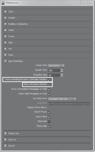
If you accidentally click the Do Not Show Learning Movies Again or Do Not Show This Welcome Window Again check box, and want to bring them back, you can do so in either of two ways:
Choosing the Learning Movies menu item under the Help menu
Selecting the Show Learning Movies in Welcome Window and Show Welcome Window check boxes in the Windows → Preferences menu item (Figure 2.3)
After you either pick a primitive or open a file from the Welcome screen, you are in the main viewport, where you will be doing all your work in Mudbox. The main viewport is divided into three main frames (Figure 2.4): the Heads-Up Display (HUD), the East Frame window, and the South Frame tray.
There is also a menu bar at the top of the screen and a status bar at the bottom of the screen that give you information about your scene, errors, and information relative to your actions.
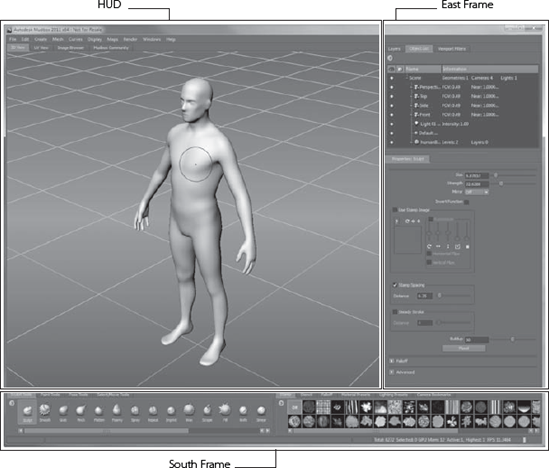
The Heads-Up Display (HUD) has four tabs:
3D View, where you will sculpt and 3D-paint your creation. This is where you will spend the bulk of your time in Mudbox.
UV View, where you will see the way your textures and paint are applied to the UVs of your image. If you are unfamiliar with UVs or what they do, don't worry, because they are covered in depth in Chapters 3, 4, 5, and 6.
Image Browser, where you will browse your texture and image libraries to pick the textures and image-based lighting (IBL) images to apply to your creation.
Mudbox Community, where you can find and share resources such as stamps, stencils, base mesh models, tutorials, and samples of your work. You can also vote on community members' work and get feedback on yours. You have to be online and connected to the Internet to access the Mudbox Community.
The 3D view is where all the creative magic happens. When you first see the 3D view, it consists of a gradient background and a grid. Imagine the rectangle where the 3D view is located as a viewfinder of a camera that you are looking through. There are many other standard and customizable viewports, but the one you start with is called the Perspective camera.
You will go through changing the camera to standard orthogonal or custom cameras in later chapters, but whatever your camera choice, you are able to see only one camera's contents in the 3D view. This is different from other 3D applications, because most of them usually have three or four camera views when you first start up.
There are some other things that pop up in the 3D view as you start working on your model. After you start dividing your model or stepping through its subdivision levels, you will see the subdivision level as well as the number of polygons in your model in a window at the top-right corner of the 3D view (Figure 2.5).
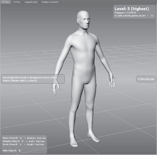
You will also get a status indicator at the center right of the 3D view, telling you which mirroring method is activated Figure 2.5). You will learn more about how to use mirroring to sculpt and paint symmetrically in Chapters 5 and 7.
You will also occasionally get tool help that shows up in the left part of the 3D view. You can turn off the informative messages if you wish; you can do so in the User Interface Section of the Windows → Preferences (Mudbox → Preferences on the Mac) dialog box.
You can turn off the gradient background by deselecting the Gradient Background option in the Display menu.
You also have context-sensitive menus that you can activate in the 3D view by right-clicking on either the canvas or an object in the canvas. When you right-click on the canvas, you get a subset of the Display menu. When you right-click on an object, you get a menu that enables you to assign a new or existing material to the object, edit the material that is assigned to it, and rename or delete it or find out about its properties.
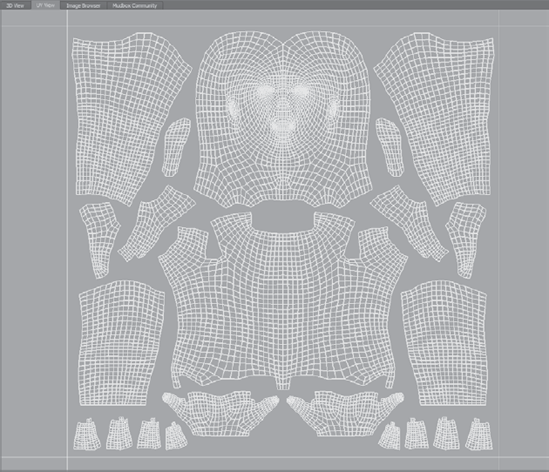
The UV view is where you see your active model's UV texture coordinates in addition to the active paint layer (Figure 2.6).
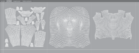
This view enables to you to see UVs in the first quadrant (or tile region) in addition to ones that are laid out in multiple tiles (Figure 2.7). Here you will also see your different maps and layers applied to your UVs.
Note that all of your UVs should be laid out before your model gets into Mudbox. This view is just for viewing the UVs and textures applied to them and not for creating, interacting with, or changing the UVs.
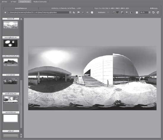
The Image Browser is a viewer that helps you view your 2D image library. You can visually select images to be stamps, stencils, image planes, or high dynamic range (HDR) image-based lighting (IBL). Think of it as a sophisticated version of a File Open dialog box for 2D images.
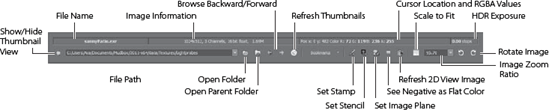
The Image Browser is divided into three parts: the toolbar, or ribbon, on top; the thumbnails on the left; and the 2D view in the center (Figure 2.8).
The ribbon, or toolbar, is where you sort through your images, get information about them, and assign them to the various roles such as image plane backdrops, a stamp to sculpt with, or a stencil to paint on your model (Figure 2.9).
To point the Image Browser at an image folder, do one of the following:
Type the image path in the File Path text box.
Click the Open Folder button and navigate to the image folder with a familiar File Open dialog box.
Click the Open Parent Folder button to move up a level in the folder hierarchy.
Use the Browse Back or Forward buttons to cycle through the folder you worked with in the session. This is similar to the Back and Forward buttons in your favorite browser.
Pick a folder from the list in the Bookmarks drop-down list. Within this drop-down list is also where you set your favorite image folders as bookmarks to save time navigating to them in future working sessions, or to quickly jump from one bookmark to another without having to navigate your hard drive to get to them. Setting bookmarks for your texture, stamp, stencil, and current working directories will save you a lot of time during a working session. After you select a folder or directory, the images in that directory will show up in the thumbnails strip to the left of the Image Browser. You can enlarge this strip to see more thumbnails by dragging the separator between the thumbnail strip and the 2D view.
Note
In addition to thumbnails, you will see folders in the left pane of the Image Browser view with the name of the folder on the bottom of the picture of a folder. Make sure you click on the picture of the folder above the name and not the folder picture below the name. Because the image of the folder appears closer to the name of the folder above it, it is a common practice and source of frustration to mistakenly click the folder under the name.
You can show and hide the thumbnails by clicking the Show/Hide Thumbnail View arrow icon to the left of the file name text box. You can cycle through the images sequentially by pressing the spacebar.
After you have selected an image, the information section of the toolbar Figure 2.9) displays the image's name, dimensions in pixels, number of color channels, bit depth (8, 16, 32), and file size. Next to the image information you will see an information area that changes values as you move the mouse over your image. This section shows information about the image under the pointer, such as the X and Y position, the Red, Green, Blue, and Alpha (RGBA) values, and whether you have a high dynamic range (HDR) image, and its exposure value.
When you are viewing an HDR image, you can use the + and − keys to go up or down, respectively, in exposure value. These values are also called stops, based on the photography term f-stop, used to measure exposure. I cover HDR imagery and the significance of HDR photography in Chapter 9, "Lighting and Rendering." Press the 0 key to reset the stop, or exposure value, to zero. Note that after you go up or down in exposure value to a setting for a particular image, that exposure setting does not change as you subsequently click on different images, whether they are HDR images or not.
Note
It is a good practice to press 0 right after you navigate to a new image, especially if it is looking too dark or blown out to return the exposure level to the default value so you can see subsequent images you click on at a neutral exposure level.
The buttons on the right side of the toolbar enable you to set the image you are looking at in the 2D view as a stamp, a stencil, or an image plane (see Figure 2.9 earlier). These are covered further in future chapters, but for now, just know the location of the buttons, and that this is where you can make the assignments. If you are looking at a 32-bit floating-point HDR or a grayscale extracted displacement map image and wish to differentiate the pixels that contain negative floating-point values, click the See Negative as Flat Color button (see Figure 2.9 earlier). Negative displacement is displayed as positive values by default, and using this option helps you troubleshoot problems in an extracted normal map by seeing the negative values in green.
If you are working on your image in another application such as Adobe Photoshop, or loading an update image from a digital camera to replace the one you are looking at, click the Refresh Thumbnails button (Figure 2.9) to see the latest saved version of the image.
To have your image zoom up, down, or fit the size of the 2D view of the Image Browser, click the Scale to Fit button. You can zoom in or out of the image by using the Ctrl and + or − keys, respectively. Hold down the Alt key and click and drag your mouse or tablet on the image in the 2D view to pan around an image that is zoomed bigger than what fits in the 2D view. You can also zoom up your image at a preset value of 1×, 2×, 3×, 4×, 5×, or zoom down your image to ⅔×, ½×, ⅓×, ¼×, ⅙×, ⅛×, or 1/12× by clicking the down arrow of the Zoom Ratio combo to the right of the Scale to Fit button (Figure 2.9). You can also type an arbitrary number in the combo box to zoom your image to that size.
To rotate the image in 90-degree increments, click either of the Rotate Image buttons to rotate clockwise or counterclockwise. Note that this does not rotate the image permanently; it just does so in the image viewer. Also note that if you do rotate an image and grab it as a stamp, stencil, or image plane, the rotated image will be grabbed even though the original remains in its original orientation.
When you click the Mudbox Community tab, your main viewport essentially becomes a browser window connecting you to the http://area.autodesk.com/mudcom website, where you can download and upload resources, view community posted tutorials, browse and rate the work of Mudbox community members all over the world, or submit some of your own work to get rated by others. Community users need to use their Autodesk AREA user credentials to log in to the site.
The East Frame is grouped into two sections. The top section is composed of three tabs:
Layers, where you create and manage sculpt and paint layers
Object List, where you select and manage all the objects in your scene, such as your model, lights, cameras, and materials
Viewport Filters, which controls the rendered look of the 3D view
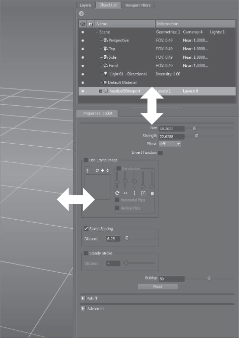
The bottom section of the East Frame contains the Properties window, which changes to display the properties of the currently selected object or tool, such as the sculpt tool, paint brush, camera, material, or light.
Depending on your preference, you can dynamically (as you are working) increase or decrease the room each section takes by moving the separator between the top and bottom section. You can also add more horizontal room to both sections by moving the separator on the edge left and right (Figure 2.10).
In the Layers window, you manage one of the most powerful capabilities of Mudbox: the ability to sculpt and paint on layers. If you have experience using Photoshop, Corel Painter, or any image-editing or compositing program that uses layers, you are familiar with how powerful and useful they can be.
The reason the skin on a Rembrandt portrait looks so vibrant and realistic is that Rembrandt used layers of oil paint with various opacities to represent the intricacies of how faces are composed of dermal and subdermal layers with various heat points and oily film. Lights in the environment reflect, refract, and react to these layers to give the subtleties of appearance that we are subconsciously conditioned to see. In Mudbox, you can do the same by painting or sculpting each layer individually, and then compositing them with different levels of opacity to achieve realistic or stylistically beautiful results.
Mudbox has both sculpt and paint layers. Sculpt layers are really useful when you are working on a model and you want to dial up or down sculpted features in a nondestructive manner. For example, if you are sculpting damage on armor for a game character and presenting it to your art director for approval, you can sculpt damage from ballistic weapons on one layer, scratches from claws or swords on another layer, and deformation from blunt-force weapons such as hammers or spikes on yet another layer. You can show and hide each one of these layers, and also dial up or dial down the opacity of the layer to choose the appropriate level of damage and fine-tune it until it looks perfect. You can also use these layers to generate blend shapes, such as expressions on a face. This is a huge time-saver and will prevent you from having to resculpt to accommodate for revisions.
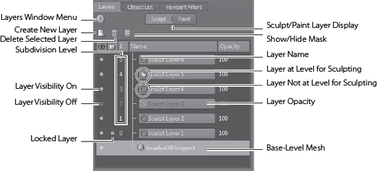
You can switch between sculpt and paint layers by clicking the Sculpt or Paint layers buttons (Figure 2.11).
The Layers window enables you to do the following:
Create, name, duplicate, mirror, flip, and delete layers.
Merge or flatten layers.
Navigate layers.
Show and hide layers.
Lock layers.
Show and hide masks on a layer.
Control the opacity of a layer.
It is very important to understand the relationship between sculpt layers and subdivision levels. Sculpt layers are layers that contain differences in the surface of the model that have been sculpted specifically in that layer. Subdivision levels denote how many times the mesh has been subdivided to get more polygons, and, in turn, display more-granular detail. This relationship can be a source of frustration if you don't understand it well. I will go over it in a couple of places in this book. Read this section and go through the example in Chapter 3 until you are completely comfortable with the relationship between sculpt layers and subdivision levels.
Your model can be subdivided many times to add more polygons so you can sculpt finer details. You start with your model at level 0. As you subdivide, your model will progress to subdivision level 1, 2, 3, and 4, and so forth based on how much detail you need and of course what your hardware is capable of crunching. Each subdivision level you go up increases the number of vertices you have, by multiplying it by 4. So if you have 24 vertices in the model you start with at level 0, subdivision level 1 will result in 96 vertices, which is 24 vertices times 4. Level 2 will have 384 vertices, the 96 vertices from level 1 multiplied by 4.
You add a new subdivision level by clicking Mesh → Add New Subdivision Level in the menu or using the keyboard shortcut Shift+D. Doing so adds a subdivision level to your model and places your model at the newly created subdivision. You have to be at the highest existing subdivision level to be able to add a new level; otherwise, when you click Mesh → Add New Subdivision Level or press Shift+D, you will go up to only the next level that's already there. For example, if your model has four subdivision levels, and you are sculpting on level 3, if you press Shift+D, you will go to level 4 rather than add level 5. But if you are sculpting on level 4 and press Shift+D, you will add level 5. So if you are not at the highest existing subdivision level, Shift+D does not add a level, but has the same effect as Mesh → Step Level Up, or pressing Pg Up on the keyboard.
A sculpt layer is assigned one and only one subdivision level. However, multiple sculpt layers can have the same subdivision level. For example, three sculpt layers named scars, pores, and wrinkles can all be assigned subdivision level 5. This means you will sculpt these three skin details on individual sculpt layers, and these details will be sculpted on your model at the geometry detail provided at a subdivision level of 5 in their individual layers. However, you can work on these three sculpt layers only in subdivision level 5.
You can't go down a subdivision level while you are in a sculpt layer, because it is locked at the subdivision level it was created in. For example, if you are on the wrinkles layer at subdivision level 5 and you press Pg Dn to go down a subdivision level, you will get a No icon in front of the wrinkles layer in the Layers window, and you won't be able to sculpt your model until you either go back to subdivision level 5 or move off the layer by selecting another layer that is assigned the subdivision level 4. If you attempt to sculpt on a layer at a different subdivision level, you will get a dialog box explaining that the layer is locked at a specific subdivision level, and the options you have are either to be able to sculpt on this layer by going the subdivision level assigned to it, or creating or going to an existing layer that has the current subdivision level assigned to it.
You assign a level to a sculpt layer by selecting the sculpt layer in the Object List and by being at the desired subdivision level before making your first sculpting stroke on it. After you make that first stroke and the subdivision level is assigned to your sculpt layer, it is not possible to change the subdivision level assigned to that sculpt layer.
This can be frustrating because you can be on a layer but not be able to sculpt on your model. Before you start digging around in properties or thinking there is a problem with the software, look at the sculpt layer to see whether a red circle with a line through it appears next to the layer name. This symbol indicates that you are at a different level than the one to which the sculpt layer was assigned. That's why you are not able to sculpt on it. To fix this, either create a new layer for the level you are on, or click on the base-level mesh in the Sculpt Layers window.
To create a sculpt layer, do one of the following:
Click the Create New Layer icon (refer back to Figure 2.11).
Click the Layers window drop-down menu icon and choose New Layer.
Right-click anywhere inside the layer list area and choose New Layer.
To delete a sculpt layer, do one of the following:
Click on the layer to be deleted, and then click the trashcan icon (Delete Selected Layer) in the Layers window (Figure 2.11).
Click the Layers window drop-down menu icon and choose Delete Selected.
Right-click anywhere inside the layer list area and choose Delete Selected.
To duplicate a sculpt layer, do one of the following:
Click the Layers window drop-down menu icon and choose Duplicate Selected.
Right-click anywhere inside the layer list area and choose Duplicate Selected.
To select a sculpt layer, click on it. You will not be able to select multiple layers, but you can merge multiple layers by making sure they are visible and that other layers are not, and then choose Merge Visible from the Layers window menu. To show or hide a sculpt layer, click the little Layer Visibility dot or circle under the eye icon (Figure 2.11). To flatten or merge all sculpt layers into one, choose Flatten from the Layers window menu.
You can save a version of your sculpture, make changes to it, load the original back in as a layer, and use the opacity slider to blend the two sculpts. To do this, choose Import Layer from the Layers window menu, navigate to the .mud or .obj file, and then use the opacity slider to blend them.
You can also flip and mirror the layer along the x-, y-, or z-axis or the tangent by choosing the appropriate option from the list in the Flip and Mirror submenus from the Layers window drop-down menu icon. Chapter 5 covers mirroring.
The steps for operations on sculpt layers (such as selecting, deleting, duplicating, and showing and hiding) that you learned in the previous section all apply to paint layers as well, with one exception. When you create a new paint layer by selecting New Layer, you get the dialog box in Figure 2.12.
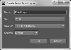
Here is where you choose the size of your images, which are referred to as maps, for the paint layers 256, 512, 1024, 2048, and 4096. These numerals refer to the number of pixels, and of course, a map is square so 2048 is actually 2048 × 2048 and is also referred to as a 2K map. You will mostly use 1K, 2K, or 4K maps depending on how much detail will be visible in your resulting output. In film or TV, close-ups require more detail; in games where textures have to be loaded and rendered in real time in the midst of action, you want to optimize memory usage by having smaller textures.
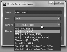
The Save As drop-down menu is where you choose the file format for your maps (Figure 2.13). The options are as follows:
PNG [8 bit, RGBA]
TIFF [8 bit, RGBA]
TIFF [16 bit Integer, RGBA]
TIFF [32 bit Floating Point, RGBA]
Photoshop [8 bit, RGBA]
Targa [8 bit, RGBA]
OpenEXR [16 bit Floating Point, RGBA]
OpenEXR [32 bit Floating Point, RGBA]
You can save your images in four lossless file formats in 8-, 16-, or 32-bit depth, and all the images formats save four channels: Red, Green, Blue, and Alpha (RGBA). The four lossless file formats are as follows:
PNG Portable Network Graphics, a popular graphics format.
TIFF Tagged Image File Format developed by Aldus, now Adobe, is popular with the print and document imaging world.
TGA Truevision Graphics Adapter, or Truevision Advanced Raster Graphics Adapter (TARGA) is a ubiquitous file format for storing textures because of its ease of implementation.
OpenEXR OpenEXR is a high dynamic range (HDR) file format released as an open standard by Industrial Light & Magic (ILM).
As for which format is the best to use, it depends on the project or the company's production pipeline. Many game studios use TGA for textures, but OpenEXR is a growing open standard that has support for 32-bit depth and HDR. In this book, we will mostly be using TIFF, TGA, and OpenEXR.
You choose a channel type when you create a new paint layer. These are Diffuse, Specular, Gloss, Incandescence, Bump Map, and Reflection Mask (Figure 2.14). You can have multiples of these layers, and they are grouped in the Paint Layers window by channel (Figure 2.15).
Diffuse Specifies the base color of your sculpture. Think of it as the pure color in an environment that has no external influencing factors.
Specular Specifies the color of the specular highlight on the material. This is best described as the property that gives objects their shine. This is a grayscale image that specifies which parts of your model are allowed to show specular highlights (white and lighter grays) and which parts are not (usually black or darker grays).
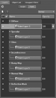
Gloss Specifies the size of the specular reflection. It is also a grayscale image for which the darker the value, the smaller the size of the specular highlight.
Incandescence Incandescence simulates the emission of light by the material, independent of the lights in the scene. This paint layer indicates the brightness of the color on a material but does not affect or illuminate other models or parts on the scene.
Bump Map Bump maps give a fake sense of depth. Darker values appear to be inset, and lighter values appear to bulge out. You will not see the effects of a bump map on the edge of the geometry of a model because there is no displacement or chiseling in, it's just an optical illusion. The bump map is a grayscale image in which areas that are at 50 percent gray are flush with the surface of the model. Areas with darker colors are indented, and lighter ones appear to bulge out. The Bump Map is also the channel in which you can visualize an extracted displacement map on your model.
Normal Map The Normal Map channel, based on RGB colors, is the channel at which you can visualize an extracted normal map on your model.
Reflection Mask This is a grayscale image that specifies what part of your model reflects the environment.
Note that the Mudbox Material used in the 2009 and 2010 versions of Mudbox had some additional channels such as Specular 2 and Gloss 2, and did not have others such as Incandescence and Normal Map. It also had some naming differences such as Bump Value instead of Bump Map. The channels in the older Mudbox Material are still supported with later versions of Mudbox to maintain compatibility; however, they are not available to you when you are creating materials:
Specular 2 A second specular that affects the fringes of the specular highlight. This setting is useful in low and oblique lighting situations.
Gloss 2 A second gloss component that affects the size of the outer regions of specular highlights. This setting is useful in low and oblique lighting situations.
Of all these channels, Diffuse and Normal are the only two in which color is relevant. Even though the others can be in color too, only their saturation is relevant, unless you want the specular highlight to have a particular hue. Note that you can have multiple diffuse maps layered on top of each other to represent the layers found in nature. For example, a face has subdermal and epidermal layers that you can paint; using the powerful layers capability of Mudbox, you can dial up or down the opacity of each layer to get your perfect desired blend of the two.
To merge or flatten paint layers into one layer, click Layers window drop-down menu → Merge Visible. This is a good practice if you are finished with the layers and don't need to make further adjustments and edits to them or their opacity, because this reduces the number of texture files and saves texture memory.
Some things to note when merging layers:
All visible layers are merged for the selected paint layer channel. You can temporarily turn off any layers you don't want merged by using the Layer Visibility setting (click the little dot or circle under the eye icon in the Paint Layers window and make sure the circle is not filled). You will then select one of the existing layers to be the resulting layer.
When layers are merged, the existing layer opacity values are frozen. Even though you can still adjust the opacity of the resulting layer, you can no longer adjust the opacity of the original individual layers.
When layers of different resolutions are merged, the layer with the highest resolution determines the resulting layer's resolution. If you merge an image with a resolution of 1K with two images that are 2K, the resulting layer adopts the highest resolution, in this case 2K. Similarly, when layers with different bit depths are merged, the resulting layer has the same bit depth as the image with the highest bit depth.
Note
Before you merge layers, it is a good practice to first save or export your initial layers, and take notes on their opacity, in case you do have to go back and correct something. In that case, you just import the images, make the adjustments, and merge the layers again.
If you want to export paint layers, select them and choose Layers window drop-down menu icon → Export Selected. You can also import images as layers by choosing Layers window drop-down menu icon → Import Layer.
When you save your model (for example, torso.mud), Mudbox stores all your layers as image files in a folder (for example, called torso-files).
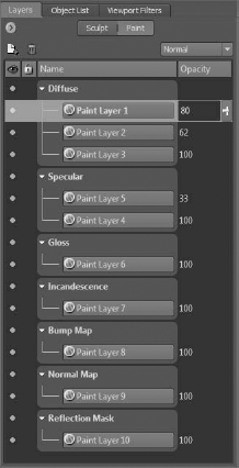
You can rearrange the top-to-bottom order of paint layers within their channels by dragging and dropping them in the Paint Layers window.
Paint layers can also be composited by using one of five blend modes that work similar to blend modes in Adobe Photoshop layers. Every layer starts out with the default Normal blend mode that you can change by using the blend mode drop-down menu. To determine the blend mode of a paint layer, click on it, and its blend mode will be indicated in the blend mode menu. The five blend modes available in Mudbox are as follows:
Normal The default blend mode for a paint layer. With this blend mode, the composite of all the layers will result only in the top paint layer in the layer stack unless you change the opacity setting to a number less than 100, or it has some transparent regions due to the image having an alpha channel that indicates what parts of it are transparent.
Multiply The value of each pixel in the layer is darkened by a value greater than or equal to the value of pixels occupying the same location on layers on top of it in the layer stack. It is useful for darkening an image, especially with an ambient occlusion map. Multiplying with white does nothing, while screening with black produces black.
Add The value of each pixel in the layer is brightened by a value less than or equal to the value of pixels occupying the same location on layers on top of it in the layer stack. Although Screen seems to do the same thing as the Add blend mode, the lightening effect produces no change in contrast because of the mode being applied in a linear fashion, producing a more extreme lightening result than Screen.
Screen The value of each pixel in the layer is brightened by a value less than or equal to the value of pixels occupying the same location on layers on top of it in the layer stack. The resulting effect is the opposite of the Multiply blend mode. Screening with black does nothing, while screening with white produces white.
Overlay Is a combination of Multiply and Screen. The Multiply blend mode is applied to a pixel if it is at the bottom 50 percent of the overall brightness of the image, and the Screen blend mode is applied to the pixel if it is at the top 50 percent. The base color on the layer is not replaced but is mixed with the blend color to reflect the lightness or darkness of the original color. This blend mode is useful for replacing patterns and colors while preserving the highlights and shadows of the base color.
Now that you have read a description of the Layers window, we will cover the Object List and Viewport Filters windows in the East Frame.
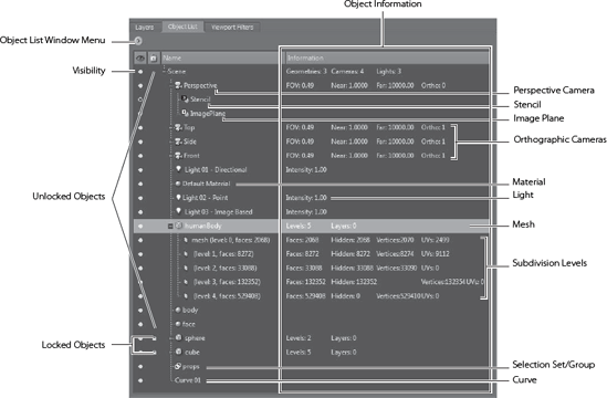
The Object List lists everything in your scene. This includes all cameras with their image planes and stencils, lights, materials, selection sets (or groups), and polygonal meshes with their layers (Figure 2.16).
This window is similar to the Outliner in Maya. You can use the Object List window drop-down menu to filter what you see in the Object List window. You can view/hide and lock/unlock the components of this list by clicking the eye icon next to the item.
You can open another or multiple Object List windows by clicking Windows → Object List (or Window → Object List on the Mac) from the menu bar. This is a good practice because you will always want to have the Object List visible and accessible while you are working. You can open an Object List window and move it off to the side or to your second monitor if you have one. You can also open multiple windows of the Object List window and filter each one differently.
If the final result of your work in Mudbox is not destined to be rendered in another 3D application, renderer, or game engine, the rendering in Mudbox can be enhanced to produce some great effects. Mudbox gives you the capability to apply some post-processing visual effects to your scene in 3D view by using viewport filters (Figure 2.17).
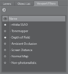
The primary purpose of these filters is to re-create as closely as possible the environment of the application in which your sculpture will be rendered. You can, however, use the results of the render and variations of it created with the various viewport filters to composite it into proof-of-concept images. Another advantage of the Mudbox rendering engine and viewport filters is that they operate in real time, so you could actually work on your sculpture in real time with filters turned on.
The standard viewport filters included in Mudbox are:
The Tonemapper filter enables you to change the color tone and gamma of your 3D view.
The Depth of Field filter enables you to specify a range outside of which the image is blurry and out of focus, as you would with a camera lens.
The Ambient Occlusion filter gives your sculpture an occlusion effect that makes cracks, crannies, and corners appear darker. This effect makes your sculpture look more realistic, especially if you have a lot of high-frequency details such as wrinkles and scratches.
The Screen Distance filter displays a depth map of the objects in the 3D view. Based on your settings, you see a gradation between black and white depending on the distance of the object from the camera's viewpoint. It's useful for creating a depth map to composite into your final image, or for quickly creating stencils, stamps, or displacement maps from sculpted objects.
The Non-Photorealistic Effect filter makes the objects in your scene look hand-drawn on textured paper.
The Normal Map shader shows objects by using color values based on the orientation of their surface normals. This filter is useful for previewing normal maps without having to use the extract texture maps feature.
To turn these filters on, click the circle icon next to them. To change the properties of a filter, click on the filter itself in the Viewport Filters window, and its properties will appear in the bottom section of the East Frame. Chapter 9 details the properties of these viewport filters, in addition to two others, the Nvidia Ambient Occlusion, and the CG filters, that are not displayed by default, in more depth.
The bottom section of the East Frame is the Properties window (Figure 2.18). It does not have tabs, and its contents change depending on what you choose in other windows. For example, if you choose a sculpting tool, the properties of that tool will appear in the Properties window. You can also open additional Properties windows if you need to work on more than one simultaneously, by clicking Window → Properties and choosing a property. This additional Properties window will appear in a floating window that you can move to another monitor or position.
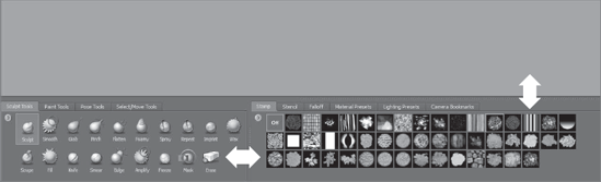
The South Frame (Figure 2.19) contains your tools, stamps, stencils, presets, and bookmarks. Mudbox comes with some default options for these, but you can customize this list with your own additions, omissions, and order.
Note
The items on a tray can be reordered by dragging them while pressing the middle button of your mouse or the back button on the stylus.
The South Frame is grouped into two sections. To the left are your tools, and to the right are stamp and stencil libraries, material and lighting presets, and camera bookmarks. Depending on your preference, you can dynamically (as you are working) increase or decrease the room each section takes by moving the separator between the left and right section. You can also add more vertical room to both tray sections by moving the separator up and down (Figure 2.20).
The Sculpt Tools tray (Figure 2.21) is where you will pick the tools that manipulate the geometry, or shape, of your model. There are 19 standard tools you can choose from, and all of these tools have properties that can be customized for your work session. These customized versions can be added to the Sculpt Tools tray if you need to use them on a future project.
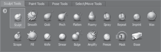
Table 2.1 lists the sculpt tools and what they do in general. We will go into more depth about their properties and customization in examples of their use in other chapters.
Table 2.1. Sculpt Tools
ICon | Name | |
|---|---|---|
Sculpt | The Sculpt tool (or a variation) is the tool you will use to do most of your sculpting in Mudbox. It is used to build up or take away surface depth on your model. | |
Smooth | The Smooth tool gets rid of hard or pixilated edges to produce a smoother gradation in depth on your model. You will use this tool in conjunction with the Sculpt tool for the bulk of your work in Mudbox. | |
Grab | The Grab tool enables you to move vertices and geometry on the surface of the model. This tool enables you to make adjustments to the form of the model. | |
Pinch | The Pinch Tool pulls vertices together to create a pinched look. You will be tempted to use this to create hard edges and creases, but I strongly recommend against it because it creates problematic geometry. You will see why and learn other ways to get the same effect in chapter 5, "Digital Sculpting, Part I". | |
Flatten | The Flatten tool is indispensible for creating planes in your geometry. Artists use planes to block out 3D shapes, and the Flatten tool enables you to make those planes. | |
Foamy | ||
Spray | The Spray tool uses a stamp from the Stamp tray and randomly places or sprays relief on the surface of your object. Very useful for adding pores or random scratches on a surface, among many other things. | |
Repeat | The Repeat tool is perfect for creating repeating linear patterns such as for stitching, screws, bolts, or rivets. The repeating shape is determined by the stamp. | |
Imprint | The Imprint tool is used to either depress or pop out an instance of the stamp on the surface of your model. | |
Wax | The Wax tool builds up or removes material from the surface of your model as if you were adding material to it. This is a useful tool for sculpting because it simulates adding material to the surface, like adding clay in traditional sculpture. | |
Scrape | The Scrape tool is used to remove or scrape off shapes that protrude. It establishes a plane at the first vertex you click on the surface and flattens everything above that plane. | |
Fill | The Fill tool fills holes and cavities on your model. Upon clicking the surface, it establishes a plane at the average of vertices within the area of the circle around your cursor and fills holes up to that plane. | |
Knife | The Knife tool is used to cut strokes into the model by using a stamp. | |
Smear | The Smear tool moves the vertices under the area within the circle around your cursor in the direction you move the cursor. Like the Pinch tool, it could create problematic geometry and should be avoided if possible. It is useful for moving a group of polygons along the plane of the camera, Turn the wireframe on to see the effects of the Smear tool. | |
Bulge | The Bulge tool bulges out geometry along the vertices' normals, which bulges out the geometry beneath the area within the circle around your cursor on all sides versus just upward, creating an inflated look. | |
Amplify | The Amplify tool establishes a plane upon clicking a surface and moves vertices that are under it lower, and ones that are above it, higher. It is good for bringing out features that might appear too subtle, such as wrinkles or muted sculptural details. | |
Freeze | The Freeze tool locks, or freezes, vertices on the surface of your model so they can't be moved with any of the sculpting tools. The frozen area will be a solid blue. Based on your falloff, the solid blues are not movable, and as the opacity tapers, the vertices will be more movable. The Freeze tool freezes vertices on all levels. | |
Mask | The Mask tool lets you hide or show the sculpting done on a layer from the one beneath it. This is nondestructive, so you can dial in and out to determine how much of your sculpting on the level shows through. Think of it as having an opacity slider that works on parts of the model that you paint a mask on. This is a very powerful tool we will cover in depth in chapter 5, "Digital Sculpting, Part I". | |
Erase | The Erase tool erases the sculpting you have done on a layer. |
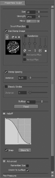
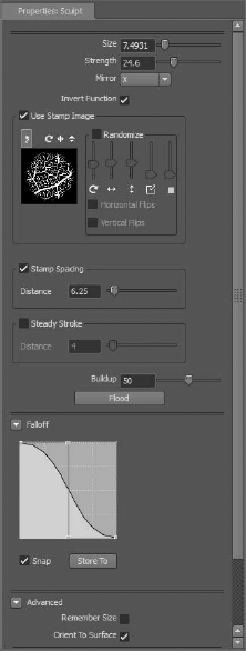
As you click these sculpt tools, their properties appear in the Properties tray (Figure 2.22 and Table 2.2). Note that all the sculpt tools have most of these properties, but some of the properties are available for only certain tools.
Table 2.2. Sculpt Tool Properties
The Paint Tools tray (Figure 2.23) is where you pick the tools that enable you to paint on the surface of your model. There are 16 standard tools you can choose from, and all of these tools have properties that can be customized for your work session. These customized versions can be added to the Paint Tools tray if you need to use them on a future project.
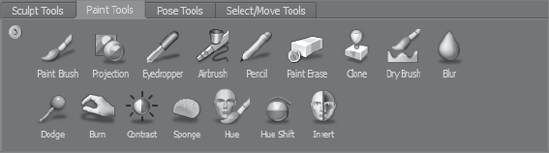
Table 2.3 lists the paint tools and what they do in general. Chapter 8, "3D Painting," provides more depth about their properties and customization in examples of their use.
Table 2.3. Paint Tools
ICON | NAME | |
|---|---|---|
Paint Brush | Paints on the surface of the model and layer. | |
Projection | Applies the color from images and textures by using a stencil image you select from the Stencil tray. | |
Eyedropper | Picks up a color from your model, under the cursor, and assigns it as the current paint color. | |
Airbrush | Applies paint on the surface like a real-world airbrush but with less opacity and feathered edges than the Paint Brush. | |
Pencil | Draws a thin stroke with sharp edges. | |
Paint Erase | Erases paint from the active paint layer. | |
Clone | Samples paint applied on one area of a model and applies it onto another area of the same model. Ctrl+click to set a source point from which you will sample, and then paint in another location to clone the paint from the source point. | |
Dry Brush | Applies paint based on the depth of the surface of your model. It will allow you to paint only raised areas or only recessed areas by inverting the brush's function. | |
Blur | Blurs the painted area to which the brush ring is applied. | |
Dodge | Enables you to lighten the painted area to which the brush ring is applied. | |
Burn | Enables you to darken the painted area to which the brush ring is applied. | |
Contrast | Increases or decreases the difference between light and dark pixels on the active paint layer to which it is applied. | |
Sponge | Makes subtle adjustments to the color saturation of pixels on a texture on the active paint layer to which it is applied. | |
Hue | Enables you to replace the hue of pixels on a texture on the active paint layer to which it is applied with a user-specified color hue. | |
Hue Shift | Shifts the hue by the amount specified in degrees around the color wheel relative from its current value in a counterclockwise direction. | |
Invert | Inverts the color hue under the region of the brush ring in the current layer. |
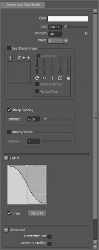
As you click on these paint tools, their properties appear in the Properties tray (Figure 2.24 and Table 2.4).
Table 2.4. Paint Tools Properties
The Pose Tools tray (Figure 2.25) is where you will select one of four tools to pose your model
Table 2.5 lists the pose tools and what they do in general. Chapter 6 goes into more depth about their properties and customization in examples of their use
The pose tools have very limited properties. The Create Joint tool has only a falloff property. The Pose tool has an invert operation that also can be invoked by pressing down the Ctrl key. The Weights tool has properties similar to that of the Paint Brush tool, and the Move Pivot tool has no properties.
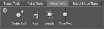
Table 2.5. Pose Tools
NAME | ||
|---|---|---|
Create Joint | Enables you to create a joint, specify its area of influence falloff by a boundary axis, and the area affected by the joint. | |
Pose | Enables you to rotate, translate, or scale the weighted region associated with a joint. | |
Weights | Enables you to add to or erase from the weighted region that is associated with a joint by painting on or removing color from areas you want affected, the same way you would use a paint tool. | |
Move Pivot | Enables you to move the position of the pivot point and shift the origin of the rotation, translation, or scaling posing operation. |
The Select/Move Tools (Figure 2.26 and Table 2.6) tray has tools that enable you to select, reposition, rotate, or scale the models in your scene, or select faces on your model.
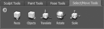
You select faces on your model to specify an axis of symmetry. You can also select faces or objects to hide them in the 3D view when working on complex models.
You need to have an object selected to export or isolate it to a separate file. Selected faces on objects can be saved and restored by grouping them into selection sets. You create a selection set by selecting faces and objects you wish to group and clicking Create → Selection Set.
Table 2.6. Select/Move Tools
ICON | NAME | FUNCTION |
|---|---|---|
Faces | Selects faces along your stroke. Clicking off the model deselects the current selection. Press Shift+A to select all the faces. | |
Objects | Selects the object you click. Clicking off the model deselects the current selection. A better way to select an object is to select it in the Object List by its name. | |
Translate | Brings up the transform manipulator to move the object in the 3D view. Click the arrows to move the object in the direction of the axis. | |
Rotate | Brings up the rotate manipulator to rotate the object in the 3D view. Drag the circular rings to rotate the object. | |
Scale | Brings up the scale manipulator to scale the object in the 3D view. Drag on the center box to scale uniformly across all axes, or on the boxes at the edges of the axes to scale along one specific axis. |
The properties for the Faces and Objects tools are the same as those for the Sculpt and Paint Brush tools.
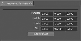
The Properties for Translate, Rotate, and Scale consist of four rows of X, Y, and Z coordinates and a Center Pivot button (Figure 2.27).
This Properties window serves both as a place to input coordinates as well as a place to see what the coordinates of an object's pivot point are. Each object has a pivot, which is a point in space that you can think of as its handle. You move the object by its pivot. Rotate the object around its pivot or scale it up or down around its pivot. The pivot location is assigned to the object before it is brought into Mudbox, but you can change it in Mudbox if you so choose by typing the coordinates in the Pivot row of the Properties window. I highly recommend that you do all your translation, rotation, and scaling outside of Mudbox, because 3D applications such as Maya have much better and more-comprehensive translation, rotation, scaling, and pivot manipulation tools.
The Stamp tray (Figure 2.28) is where you will pick a stamp to use for sculpting and painting from thumbnails of your stamp library. Your selected stamp shows up with a highlight around it in the tray, and also in the Properties tray of your tool. If you do not want to use a stamp, click the Off thumbnail.
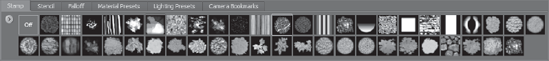
If you are sculpting with a stamp, you are using it for its value, meaning the lighter areas are used to impress or indent the stamp on a surface, and the darker areas do not make as much of an indentation. Mudbox comes with a variety of stamps, and you can add your own. If you are painting with a stamp, you are using it as a brush to apply its color value to the surface of your model.
The Properties settings of your tool determine the frequency, spacing, and orientation of how the stamps are generated.
The Stamp tray menu enables you to add, delete, or rename a stamp. The best place to add stamps is in the Image Browser. Your stamp library is located in your user directory under the DocumentsMudbox2011datastamps folder. I recommend you open a few stamps in Photoshop to see what they look like so you know what characteristics to apply when creating your own.
The Stencil tray (Figure 2.29) is where you will pick your stencil from thumbnails in your stencil library to apply on top of your 3D view in order to paint or sculpt the pattern of the stencil onto your image.
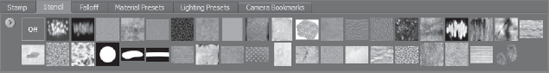
Whereas a stamp is applied to the tip of your tool, the stencil is applied to the viewing plane of your 3D view, and you will sculpt or paint through it. If you are sculpting through a stencil, you are using it for its value, meaning the lighter areas are used to impress or indent the stencil on a surface, and the darker areas do not make as much of an indentation. Mudbox comes with a variety of stencils, and you can add your own. If you are painting with a stencil, you are painting its color value onto the surface of your model.
The Stencil tray menu enables you to add, delete, or rename a stencil. The best place to add stencils is in the Image Browser. Your stencil library is located in your user directory under the DocumentsMudbox2011datastencils folder. I recommend opening up a few stencils in Photoshop and seeing what they look like so you know what characteristics to apply when creating your own.
The Falloff tray (Figure 2.30) lists some default Falloff presets and enables you to add your own.
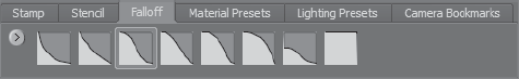
You edit falloff curves in the Falloff section of your tool's Properties tray (Figure 2.31).
After you determine that a falloff is the one you wish to use in the future, click the Store To button under the falloff curve to save it to your Falloff tray.
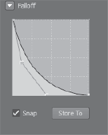
When looking at a falloff, consider that the left is the center of your brush, and the right is the edge, and the higher the curve, the deeper the imprint.
In the Properties tray of your tool, you can modify the falloff curve by moving the points on the curve to adjust it:
You can add points to the falloff curve by right-clicking (back button on the stylus) and selecting Add Point.
Snap enables you to snap the curve points to the axes.
To delete a point, right-click on it and select Delete Point from the menu.
The Material Presets tray (Figure 2.32) is where you choose a premade material for your model. Again Lights, Materials, and Rendering settings in Mudbox are mostly to re-create as close as possible the environment your model will end up in. You will most likely not do too many adjustments to these settings.
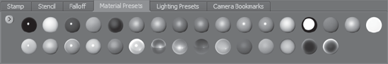
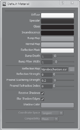
You assign a material to the model either by choosing from the thumbnails in the Material Presets tray or by right-clicking on it (back button on the stylus) and selecting Assign New Material from the menu. This opens the Material Properties tray (Figure 2.33), in which you can customize the material and add it to the Material Presets tray.
To edit an assigned material, right-click (back button on the stylus) on your model and select Edit Material.
Mudbox uses four types of materials that produce different looks for your model:
We will go into working with materials in Chapter 4, "Painting and Texturing an Imported Model," and Chapter 8.
Each of these materials have properties specific to them, as seen in Tables 2.7, 2.8, and 2.9.
Table 2.7. Mudbox Material Properties
Table 2.8. Simple Blinn Properties
PROPERTY | DESCRIPTION |
|---|---|
Diffuse | Specifies the base color of the material. Click the color box to change the Diffuse color and edit it by using the Select Color window. |
Specular | Specifies the color of the highlight on the material. Click the color box to change the Specular color and edit it by using the Select Color window. |
Ambient | Specifies the minimum darkness of the material. |
Shininess | Indicates the size of the specular reflection. The lower values result in wider highlights. |
Table 2.9. Lit Sphere Material
Lit Sphere Image | Specifies the image to be used for the lighting environment. This image is used to calculate the light source and works with the scene lights in your environment. |
Bump Value | Specifies the file path of the bump map image. |
Bump Depth | Specifies how high or low bumps display on the surface. Higher values make the surface look bumpier. |
Bump Filter Width | Specifies filtering on the texture used as a bump map. Values greater than 1.0 make bumps smoother, and values less than 1.0 make bumps appear sharper. |
Reflection Map | Specifies the image to be used as a reflection map. This creates a simulated environment around the model. If an image-based light (IBL) is applied to the scene, the reflection map image is replaced with the IBL image. |
Reflection Strength | Controls the visibility of the reflection map. A value of 1 causes the image to be 100 percent visible, and a value of 0 makes the material show no reflections. |
Reflection Mask | Specifies the file path for the reflection mask image. |
Fresnel Scattering Strength | Specifies the intensity of the Fresnel glow effect on the model. |
Fresnel Refractive Index | Specifies the surface area of the model that is affected by the Fresnel glow effect. A low number specifies that only the edges get illuminated. A higher number indicates that more of the model is illuminated by the Fresnel glow effect. |
CgFX-Based Materials CgFX shaders plug into applications that use the Cg programming language for programming graphics hardware. Cg was developed by Nvidia with close collaboration of Microsoft Corporation to help generate real-time cinematic-quality experiences on multiple platforms such as OpenGL, DirectX, Windows, Linux, Macintosh OS X, and console platforms such as the Xbox.
There is a README.cgfx-support.txt file in the effects folder of your Mudbox installation folder for more information on the CgFX annotations and semantics supported by Mudbox. Further information on Cg is available at the following site:
http://http.developer.nvidia.com/CgTutorial/cg_tutorial_chapter01.html
The Lighting Presets tray (Figure 2.34) has thumbnails of lighting setups and enables you to add your own. When you set up lights and create the lighting environment you want to see your model in, you can save it as a preset and apply it to other models by clicking its icon in the Lighting Presets tray.
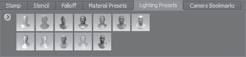
Mudbox supports three types of lights:
Point lights Point lights emit light evenly in all directions from a point in your 3D space. A point light is used to simulate an incandescent light source such as candles or lightbulbs.
Directional lights Directional lights simulate light emanating from a distant light source so that its light rays are parallel to each other when they reach the object they affect.
Directional lights are used to simulate sunshine or distant light sources.
Image-based lights (IBL) Image-based lights simulate lighting in the scene based on an image wrapped around the environment. Image-based lighting uses HDR images for generating very realistic lighting and reflection effects.
You can add many point and directional lights to your scene, but only one IBL. When you add an IBL to your image, it replaces the reflection map assigned to the materials in the scene.
All three lights have properties indicated by Tables 2.10, 2.11, and 2.12 for point, directional, and image based lights, respectively.
Table 2.10. Point Light Properties
PROPERTY | |
|---|---|
Diffuse | Specifies the color of the light. |
Intensity | Specifies the brightness of the light. |
Light Decay | Specifies how the light's intensity decreases with distance. |
Scale | Enables you to change the scale of the displayed light source sphere. This does not affect the amount of light produced, but just makes it easier to see where the light source is. |
Show Manipulator | Displays the light's transform manipulator, letting you reposition the location of the point light in X, Y, and Z space. |
Show Light | Displays a sphere to show the light's location. |
Table 2.11. Directional Light Properties
PROPERTY | DESCRIPTION |
|---|---|
Diffuse | Specifies the color of the light. |
Intensity | Specifies the brightness of the light. |
Scale | Enables you to change the scale of the displayed light source direction arrows. This does not affect the amount of light produced, but just makes it easier to see where the light source is. |
Locked to Camera | Locks the position of the light source to the camera. When the camera is tumbled, the light also gets rotated with the camera. |
Show Manipulator | Displays the light's rotate manipulator, letting you rotate the orientation of the light source. |
Show Light | Displays four arrows to show the light's direction. |
Cast Shadows | Indicates whether this specific directional light casts shadows. |
Depth Map Bias | Indicates the offset of the depth map toward or away from the light. |
Depth Map Resolution | Indicates the light's shadow depth map resolution. The higher the resolution, the smoother the shadow. |
Table 2.12. Image-Based Lighting Properties
PROPERTY | DESCRIPTION |
|---|---|
Intensity | Specifies the brightness of the light. |
Locked to Camera | Locks the position of the light source to the camera. When the camera is tumbled, the light also gets rotated with the camera. |
Displays the light's rotate manipulator, letting you rotate the orientation of the light source. | |
Image Based Light File | Specifies the file path for the IBL image. Upon adding an IBL, this file replaces the reflection map file assigned to the materials in the scene. |
The Camera Bookmarks tray (Figure 2.35) is a container for storing camera settings. When you set up a camera or change the settings of an existing camera, you can save it as a bookmark and apply it to other scenes by clicking its icon in the Camera Bookmarks tray.
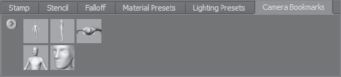
You can look at, customize, or modify cameras by clicking the camera in the Object List. Table 2.13 lists the camera properties.
Table 2.13. Camera Properties
PROPERTY | DESCRIPTION |
|---|---|
Transform | Lock Pan, Rotate, Zoom: Locks or unlocks your ability to pan, rotate, or zoom the camera. Reset: Resets the camera's Roll, Rotate, Track, and Dolly transforms. Select the check boxes you want to reset and click the Reset button. |
2D Transform | Transforms the scene based on the plane of the camera. Select the check boxes and click Reset to reset 2D transforms. |
Orthographic | Turns off the perspective. |
FOV | Specifies the camera's field of view. |
Near Plane | Specifies the distance of the near clipping plane from the camera. Clipping planes define the range the camera sees. |
Far Plane | Specifies the distance of the far clipping plane from the camera. Clipping planes define the range the camera sees. |
You can specify a stencil and an image plane for each camera. The stencil enables you to sculpt or paint through the image of the stencil. The image plane is an image you can load behind your model for reference.
You can associate a single image to a camera as an image plane. Table 2.14 lists the properties of an image plane. Table 2.15 lists the stencil properties.
Table 2.14. Image Plane Properties
PROPERTY | DESCRIPTION |
|---|---|
File | Indicates the file path for the image plane. |
Import | Imports an image plane. |
Export | Exports an image plane. |
Visibility | Specifies the transparency of the image plane. |
Specifies how far the image plane is from the camera in relation to the model in the 3D view. | |
Transformation | Moves the image plane in 3D space by specifying coordinates, and rotates and scales in 2D by specifying rotation angle and scale percentage. |
Table 2.15. Stencil Properties
PROPERTY | DESCRIPTION |
|---|---|
On | Toggles the stencil on and off. |
File | Indicates the file path for the image plane. |
Import | Imports an image plane. |
Export | Exports an image plane. |
Transformation | Moves the stencil in 3D space by specifying coordinates, and rotates and scales in 2D by specifying the rotation angle and scale percentage. |
Invert Values | Inverts the values of the stencil. |
Hide When Sculpt | Hides the stencil when you are sculpting but not when you are painting. |
Flip Vertical, Flip Horizontal | Flips the stencil. |
Use Tiles | Use tiles, and repeats the stencil in a tile pattern in the 3D view. |
Show Tiles | Shows the tiles if the preceding option is selected. |
Visibility | Specifies the transparency of the stencil. |
Multiplier | Specifies the strength of the stencil. |
Offset | Specifies the stencil deformation relative to the surface of the model. The higher the number, the more vertices are raised and pulled out. The lower the number, the more they are pushed in. Using a middle value of 50, brushing over black pixels of the stencil image pushes vertices down, and brushing over white pixels pull vertices out. |
Map extraction is not a permanent fixture in the Mudbox interface, but a dialog box that comes up when you click Maps → Extract Texture Maps → New Operation. I included it in this chapter because map extraction is a critical operation in Mudbox to export your sculpting detail work to other applications, and the Extract Texture Maps dialog box, or variation of four dialog boxes, has many components that should be available for reference in a UI tour.
In Chapter 1, we generated a displacement and normal map for the egg we created in Mudbox and transferred the surface detail to lower versions of the egg in Maya for rendering or real-time viewing. In this section, we will go through the settings in the map extraction dialog boxes in detail.
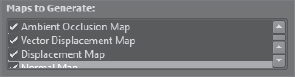
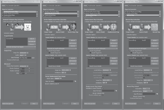
When you click Maps → Extract Texture Maps → New Operation, one dialog box comes up, but the contents of that dialog box expand out and change slightly when you click any one of the four options in the Maps to Generate section: Ambient Occlusion Map, Vector Displacement Map, Displacement Map, and Normal Map (Figure 2.36). Note that you can change the options for the listed map types only when that option is highlighted in the dialog box. This can be confusing because the options also have check boxes next to them. If you select the check boxes, you are opting to generate that specific map when you click the Extract button. If all four are selected as they are in Figure 2.36, all four maps will be generated when you click the Extract button.
To change the dialog box to the particular map, you need to click that map option to highlight it. Notice the similarities and variations in the four renditions of the map extraction dialog box as you click Ambient Occlusion Map, Vector Displacement Map, Displacement Map, and Normal Map (Figure 2.37).
After you go through this operation, the settings will be saved for reuse in the future. The settings subsequently appear in the Maps → Extract Texture Maps menu, after allowing you to have multiple map extraction settings for different parts of a model.
You can individually or as an aggregate generate four types of texture maps: ambient occlusion (AO) maps, vector displacement maps (VDMs), displacement maps, and normal maps. There is a graphic and text description of each map at the top of the dialog box that describes what the maps are, what the extracted maps look like, and what they do.
All four variations of the dialog box contain the target models, which indicate the name of the model to receive the extracted ambient occlusion, normal, or displacement map. This is the low-resolution version of the model that will be exported, and of course, it should have UV coordinates so that the map generated will correspond to it. You will see more on UV coordinates in subsequent chapters.
The target model is generally either the lowest or one or two levels above the lowest subdivision level of a model. For normal and displacement maps, you can change this subdivision level after the fact, by using the subdivision level drop-down list to the right of the target model name. The normal or displacement map produced represents the difference between the target model or models and the source model or models.
For ambient occlusion maps, the currently active subdivision is used for the map extraction. If you want to extract the map for a different subdivision level, you need to be at that subdivision level before you extract the AO map. Also, by default, ambient occlusion map extraction generates a map for all the visible objects in the scene. If you don't want parts of your model to be in the AO map, turn off their visibility in the Object List.
Add All and Add Selected enable you to add all the models or just the model selected in the Object List or 3D view. The Remove option removes the selected model in the Object List or 3D view from the target model name list.
If all the objects in the Target Models list share one UV tile, then when extracting maps for multiple targets, use the Generate One Map for All Targets option to generate one map for all of them.
If the target models use different materials or UV texture coordinates occupy the same UV tile location, use the Generate a Map for Each Target option.
When the Smooth Target Model option is selected, the map extraction operation calculations use a smoothed version of the target model. However, if you are extracting texture maps for games in which a faceted model is generally used, you can turn this option off.
When the Smooth Target Model option is selected, the Smooth Target UVs option smooths the interior UVs of the target model as well during the texture extraction. This feature is also useful for rendering software such as Pixar RenderMan, as this capability carries over to smooth the UV texture coordinates on a mesh during rendering to get better results.
The source model contains the sculpted details of the higher or highest subdivision level of your model. You can change which subdivision level you want to extract the map for by choosing the level in the subdivision level drop-down list located to the right of the source object name.
As in the target models extraction options, Add All and Add Selected enable you to add all the models or just the model selected in the Object List or 3D view. The Remove option removes the selected model in the Object List or 3D view from the target model name list.
When Smooth Source Models is selected, a subdivided and smoothed version of the source model is used for map extraction calculations. This prevents jagged and hard edges from being generated when you apply the extracted maps to models in other 3D applications.
If you envision both a low-resolution version of your model and a high-resolution version in the same place, you will have faces from the high-resolution model intersecting the surface of the low-resolution model in many places. The Choose Samples option enables you to specify which value to use for the extracted map if an extraction sample intersects the high-resolution version of your model more than once:
Furthest Outside samples farthest out from the source model, to the range specified by the Search Distance.
Furthest Inside samples from closest to the interior of the source model to either the target model, or the range specified by the Search Distance.
Closest to Target Model samples closest to the target model, ignoring the source model.
A tooltip image comes up when you hover your mouse over the Choose Samples property. The tooltip provides an excellent graphical depiction of the three options.
The Search Distance setting indicates the distance that samples can span to find the source model. This range samples on both sides of the target based on the Choose Samples option. The Best Guess button sets the Search Distance, taking into consideration the distances of the bounding boxes for the source and target model. If the two surfaces are not too far apart, this option generates a useful estimate.
When extracting an ambient occlusion map, the Extract Texture Maps dialog box slightly changes to include the following properties.
Quality sets the granularity of the final ambient occlusion map. You can choose from the preset values of Fastest, Fast, Normal, Good, and Best. The higher the quality setting, the more number of shadow maps are produced and combined to generate a higher-quality map. However, this is at the cost of more time required to generate the ambient occlusion map.
The Base File Name field is where you indicate the name of the extracted map. AO(%s).bmp is used as a default if you do not specify a name, where %s is substituted by the name of the model. You can click the file button to the right of the Base File Name to bring up the Save As dialog box to set a directory and choose the file format (.png, .bmp, .gif, .jpg, .tif, or .tga).
If your model contains UVs outside the 0 to 1 range in two or more UV tile spaces, this operation automatically creates separate ambient occlusion maps corresponding to each UV tile by adding a suffix of the coordinates of the tile—for example, AOhead_u1_v1.tga and AOhead_u1_v2 for a model that has UVs in two adjacent tiles.
If selected, Preview as Paint Layer adds the generated ambient occlusion map as a new Diffuse channel paint layer. This lets you preview the generated map on the model. You can also use it to view ambient occlusion on your model without using the Ambient Occlusion viewport filters.
Shadow Map Resolution indicates the size of the shadow maps generated for the occlusion map calculations. You can choose from the preset values of 256 × 256, 512 × 512, 1024 × 1024, 2048 × 2048, and 4096 × 4096.
The greater the Shadow Map Resolution, the more detailed the occlusion map and the more time it takes to generate. In general, the Shadow Map Resolution should be set to the lowest possible value that produces an occlusion map of acceptable quality.
Shadow Darkness sets the brightness or darkness of the ambient occlusion map. Lowering the value from the default of 0.5 brightens the ambient occlusion map, and increasing the value darkens it.
Shadow Contrast sets the contrast between shaded and nonshaded areas of the ambient occlusion map. This value ranges from −1 to 1, with a default value of 0. Lower values reduce contrast, producing gray values in the map, while higher values increase the contrast, producing more black and white values.
The options specific to vector displacement maps are limited to one, which is the Vector Space property.
Vector Space indicates the coordinate space for calculating vector displacement maps. The three options for vector space are as follows:
Tangent This default setting should be used if the model deforms during animation.
Object Use this option if the model is animated without deformation.
World Use this setting for environment maps.
When extracting a displacement map, the Extract Texture Maps dialog box slightly changes to include the following properties.
When the Bits per Channel option is set to 8- or 16-bit, turning on the Normalize to Search Distance option maps the results of the extraction samples to the 0 to 1 color space for displacement maps instead of the −1 to 1 range used for normal maps. As a default, Normalize to Search Distance is selected.
As with ambient occlusion, the Base File Name field is where you indicate the name of the extracted map. You can click the folder icon to bring up the Save As dialog box to set a directory and choose the file format (.png, .jpg, .bmp, .tif, .psd, .tga, or .exr), some with 8-, 16, or 32-bit depth.
Again, if your model contains UVs outside the 0 to 1 range in two or more UV tile spaces, this operation automatically creates separate displacement maps corresponding to each UV tile by adding a suffix of the coordinates of the tile—for example, disp_head_u1_v1.tga and disp_head_u1_v2 for a model that has UVs in two adjacent tiles.
Normal mapping is a way to represent highly detailed surfaces on more-simplified low-polygon versions of the mesh. In addition to depicting the surface detail, normal maps contain information to make your surface detail react to environment lighting. Normal maps are needed where low-polygon meshes are a requirement, particularly in real-time hardware rendering applications such as games, previsualization, and 3D simulations. When extracting a normal map, the Extract Texture Maps dialog box slightly changes to include the following properties.
Coordinate Space indicates whether Tangent, Object, or World coordinate space will be used to calculate the normal maps. Just like XYZ and UVW coordinates, the Tangent coordinate space on a face is set by the normal, tangent, and the binormal. A face normal is a directional line perpendicular to a surface and represents the internal or external orientation of each polygon face on a mesh. The tangent is a vector that indicates the slope of the polygonal face at a given point, and the binormal is a vector orthogonal to both the normal and tangent.
Object is the local coordinate space for the model in which the lighting of the detail shown from the normal map is based on the object itself. World is the overall scene coordinate space, in which the lighting of the detail shown from the normal map is based on the environment. Tangent is the default and the one you should use unless you have a specific need for the lighting on the detail of your model to be affected by itself or its environment.
The Compatibility field sets compatibility of the calculated normal maps with other 3D applications. The tangent space vectors are calculated using one of two methods, either the left-handed or right-handed method of determining the normal orientation. These methods determine the sequence of axes in a Cartesian coordinate system. For example, with the right-handed method, the thumb, index finger, and middle finger of the right hand are held so that they form three right angles, and then the thumb indicates the normal, the index finger the tangent, and the middle finger the binormal. Maya defaults to the right-handed tangent space setting, while 3ds Max defaults to the left-handed tangent space setting. Look at the settings for any other 3D application you use to determine its tangent space setting, and use Maya or 3ds Max as the setting to indicate right or left tangent space setting, respectively. Obviously, this does not matter if you use World or Object coordinate space because both coordinate systems are absolute.
Just as for ambient occlusion and displacement maps, the Base File Name field is where you indicate the name of the extracted map. You can click the folder icon to bring up the Save As dialog box to set a directory and choose the file format (.png, .jpg, .bmp, .tif, .psd, .tga, or .exr), some with 8-, 16-, or 32-bit depth.
As with ambient occlusion and displacement maps, if your model contains UVs outside the 0 to 1 range in two or more UV tile spaces, this operation automatically creates separate displacement maps corresponding to each UV tile by adding a suffix of the coordinates of the tile—for example, norm_head_u1_v1.tga and norm_head_u1_v2 for a model that has UVs in two adjacent tiles.
The Mudbox preferences dialog box is another dialog box that is not part of what you see on the screen, but that has many components affecting how Mudbox looks and behaves. Rather than explain every option in the preferences dialog box, I will highlight some of the more commonly used ones.
It is important to know how to reset these settings to their defaults in case you set them to options that cause unwelcome results. The user settings files are saved in the following folders for various platforms:
Mac OS X:
/Users/<username>/Library/Preferences/Mudbox/<version>/settings
<drive>:My DocumentsMudbox<version>settings
Vista:
<drive>:Users<username>DocumentsMudbox<version>settings
You can move or rename those files for Mudbox to re-create new ones with default settings.
Color is where you specify the colors of the Mudbox user interface. The ones I find most useful are the first four: Viewport Top, Viewport Middle, Viewport Bottom, and Viewport Flat. The first three specify the top, middle, and bottom colors of the 3D view gradient. Viewport Flat will set the background color if the gradient option is turned off. The other color options are pretty self-explanatory.
In the Render options, I use only the Limit Wireframe to Level option. This is extremely useful if you want to display a lower-level wireframe on a higher-subdivision-level model (Figure 2.38). Even though the grid is a good visual guide to tell you how high your subdivision level is, as you get into higher subdivision levels, the grid size gets really small and becomes more of a disruption. Figure 2.38 shows the difference between this setting at the default value, which is 10 on the image on the left, versus a value of 2 on image on the right. You can choose 0 to have the absolute lowest level.
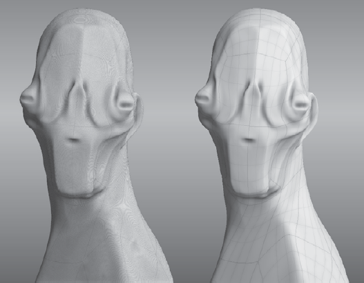
The other Render options will help speed up your display while working, but I recommend leaving them alone or recording their default values before tinkering with the settings.
FBX, which is short for Filmbox, is an interoperability file format owned and developed by Autodesk. The FBX section is where you specify the preferences with which you will use the FBX file format to import and export geometry, UVs, cameras, and materials in and out of Mudbox.
Export ASCII FBX is an option I usually select if I need to troubleshoot FBX export issues. I would leave this on as a default, but the ASCII version of FBX files take up a lot more hard drive space because the files are larger than their binary counterparts.
When turned on, the separate sculpt layers on the current subdivision level are exported as individual and separate blend shapes. When loaded into Maya or 3ds Max, separate blend shape targets can be modified with blend shape sliders very similar to the Layer Opacity sliders in Mudbox. The default setting for this is off, and the selected object is exported at its current subdivision when exporting it as .fbx.
The Paint section is where you specify the preferences of the paint tools and their effects in Mudbox.
There are many useful and self-explanatory options to turn on and off various user interface options in the User Interface section of the preferences dialog box. The one option I want to highlight is the Get Help From option. This is set to Autodesk Web Site by default, which is the setting you want if you are connected to the Internet. However, if you are at a location with slow or no Internet access or such as when you are mobile, or on a set, you can redirect this path to read the help from your hard drive. The challenge with setting the help to a local file is that Autodesk constantly updates and edits the help on the website, and accessing help locally from your hard drive will not have the latest reversions. Note that you will have to initially download the Mudbox help files from www.autodesk.com/mudbox-docs and unzip the help file in the location specified by the Help Path text box. The default for Windows is C:Program FilesAutodeskMudbox2011helpdocs and for the Mac OS X is /Library/Application Support/Autodesk/Mudbox 2011/help/docs.
This section of the preferences dialog box has various options of what to show and hide in the status line. I always make sure that the Save Reminder option is on and set at an interval of 20 or 30 minutes. Even though a blinking red Save in the bottom-right corner of Mudbox can be really annoying, it reminds me to keep saving my model—and what would be even more annoying would be to lose an hour or two of work because I forgot to save.
The Mudbox user interface is organized intuitively, and as you continue to work with it, you will discover many new features that will help you with your work. Chapter 2 is a great place to come back to again and again if you want a description of a feature in a Properties list, a dialog box, or anything else in the Mudbox interface. Please also note that as you hover your mouse on a particular tool or area, sometimes, pop-up help will give you more information about the particular tool or option.
Even though the Mudbox user interface is laid out intuitively, you will want to customize it to the way that you work. In the following chapters, we will go through some customization options to give you the means to create your own perfect setup.