
In the preceding chapter you imported an .obj model from Maya and added some paneling detail, weathering, and wear and tear to the surface geometry. In this chapter, you will pick up from where you left off with Bertie, Ashley Wood's robot, to paint and texture it for its final output. However, before you do, you need to familiarize yourself with a few concepts.
This chapter includes the following topics:
Texture-painting models
Laying out UV maps and arranging UV shells for texture painting
Creating texture maps
Using materials and textures
Working with paint and texture layers
Using specular, gloss, and bump maps
Gathering reference images
Painting Bertie
The leading 2D texture-painting tool is Adobe Photoshop because of its wide range of paintbrushes, layering and masking features, and comprehensive set of image-processing capabilities.
In the not-too-distant past, 3D models were exclusively painted in Photoshop or other 2D image-processing and painting tools; texture artists had to paint all the textures in 2D on UV maps. One of the challenges with this process is interpreting how a 2D image will wrap around a 3D object without stretching or compressing textures. Another challenge is painting uniform patterns across seams that are cut when creating UV shells, because these UV shells are not connected on the flattened 2D UV layout. A third challenge is that, when you paint in 2D, you constantly have to go back and forth between Photoshop and your 3D application to see whether the results are acceptable.
With the introduction of 3D painting tools, this process has become easier; users can paint directly onto the 3D models in 3D. Mudbox, in addition to being a powerful and versatile digital sculpting application, provides some unique and extremely useful digital painting and texturing capabilities.
These 3D painting capabilities remove most of the barriers of 2D painting applications because you can paint directly on your model in 3D, across UV seams, and see the results of your brush strokes in real time. This does not remove the need for a 2D compositing or image-processing application such as Photoshop, but it is a huge time-saver and gives you greater creative control over the texture-painting process. The introduction of versions 2010 and 2011 now further integrates Mudbox with Photoshop by enabling you to save to Photoshop's native .psd file format, preserving the layers that can be brought directly into Photoshop.
Another big advantage of Mudbox is that you can paint on your 3D model in layers. This is useful because you can have layers that represent different details on the surface of the model. One layer could be a base material of the model; the second could be a paint layer; the third could be weathering such as dust or dirt or rust; the fourth could be decals, emblems, or posters; the fifth could be glossiness or shine; and the sixth could be bumpiness of the surface. Just as you can in sculpting layers, you can adjust the opacity and blend modes of these paint layers to show as much or as little of each layer to get the desired look.
The new Flatten to UV Space feature introduced in Mudbox 2011, which is accessible through Mesh → Flatten to UV Space, enables you to paint or edit textures on a flattened representation of the original. You can also use the Pinch or Grab tools to perform basic UV position adjustments on the model in this mode. This is extremely useful to get an idea of how your textures are distributed on the UV map and make adjustments to the textures and the UVs themselves to accommodate the results you want.
I mentioned UVs in the preceding chapter and indicated that they represent coordinates on the surface of the model. You will revisit them in this chapter as they pertain to texture painting. All UV editing on a model needs to be finalized before painting and texturing your 3D model in Mudbox to avoid misaligning UVs and your painted areas. (Chapter 6, "Digital Sculpting Part II," covers how to lay out UVs for a sculpture by using Headus UVLayout.)
For the most part, UV maps for a model take up one square UV tile, or quadrant. Some applications, such as Mudbox and Maya, support UV shells distributed to multiple-square UV tiles. The benefit of distributing the UV shells across multiple UV tiles is that you get more room per shell to add detail to your texture. However, for the most part, you will do all your UV work in the first quadrant, or 0 to 1 tile.
Whether UV shells are laid out in one quadrant or many quadrants, the UV shells should not overlap. Overlapping UV shells will cause unpredictable results in 3D applications and in your final result. The only time UV shells can overlap is when you intend to take advantage of symmetry in your model and save texture space by overlapping symmetrically identical UV shells precisely on top of each other to reuse a part of the image that is symmetrical or repeated on the model.
Make sure to leave 4 to 6 pixels of space between UV shells, and between UV shells and the four borders of the UV tile. If you fail to do so, the textures will bleed from one shell to the other, producing streaking lines on the paint you apply to your model.
The shells in your UV map can be off scale. For example, if you are texture-painting a human being and you need more space to paint the details of a face, you would want to scale up the UV shell that corresponds to the head. However, if you do that, you will have broken the proportionality of the shells. For example, if you have all the shells in the same proportion and you apply a checkered pattern to a human model, the checkered pattern will be uniform throughout the body (see Figure 4.1).
However, if you apply the same checkered pattern to the model on which you scaled up the head, you will notice smaller checkered squares on the head than on the body (Figure 4.2), because you have more UV space allocated to the head.
If you need more UV space for the entire body because, for example, you need to paint intricate tattoos on the body in addition to details on the face, you can scale up all the shells and distribute them across multiple UV tiles. Note that even though you can distribute UV shells across multiple UV tiles, they should be laid out so they are contained within the square UV tile and do not cross any UV tile borders.
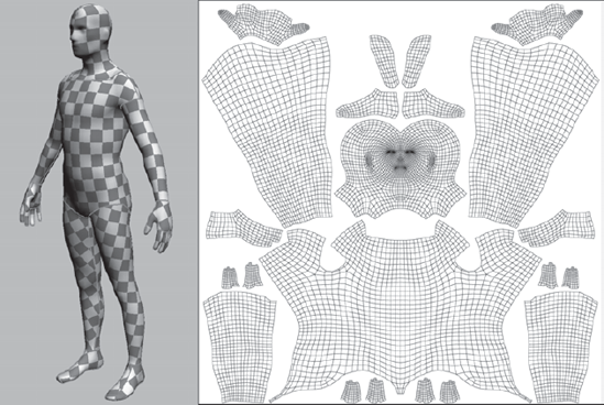
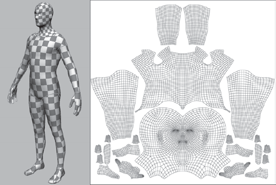
Figure 4.2. The checkered pattern appears smaller on the head because more UV space is allocated to it.
The way to determine the distribution of shells to UV tiles depends on the following factors:
Variation of detail on the model If you have a section with minimal variation in color and texture detail, and the UV shells corresponding to the section are receiving a uniform color, then you can give its UV shells less UV space. On the flip side, if you have sections that need more detail, such as a head with facial details or a mechanical part with intricate surface paneling and text, you want to give the shells corresponding to that section more UV space.
Game requirements For games, you will want to constrain all of your UV shells into one UV tile because games need to load textures really fast and game machines need to manipulate models in real time. Games might even cram UVs for multiple objects or characters on one UV tile.
Texture types UV shells might also be distributed among different tiles by type of texture—for example, all metal UVs on a metal texture UV tile, all leather UVs on a leather texture UV tile, skin textures on a skin tile, and so on.
UV space usage Rotate and move the UV shells to take up minimal room in the UV tile and maximize UV space usage. Try to have the least number of shells possible because this maximizes the amount of utilized UV space. This must be, of course, balanced by making sure you have the minimal stretching or compression of UVs, which is usually done by cutting more seams or dividing UVs into more shells.
Texture maps are 2D images that you generate either in 2D image-processing applications such as Photoshop, or in a 3D painting application such as Mudbox. These 2D images are then wrapped around your model much like wrapping paper around a present.
After you have laid out the UVs, you can output the UV map as a flat bitmap image. Most UV layout tools, such as Headus UVLayout or UV Texture Editor in Maya, allow you to output the UVs in any desired map size. Usually these are 1K (1024 × 1024), 2K (2048 × 2048), or 4K (4096 × 4096) bitmap images. This UV image will serve as a good base layer to use if you are going to do any 2D painting on your model or as a point of reference to see where the various paint regions align with the model.
All the texture painting you will be doing will be on the tiles on which you laid out your UVs. Texture maps are generally RGB or RGBA 2D images in one of the nonlossy, popular image formats such as TIF, TGA, or OpenEXR. You can create one or multiple texture maps to apply to your UV map. Multiple images are subsequently composited as layers and flattened to form the final texture map that will be mapped on your model for its final presentation.
We can generally tell what an object is made of by the way it looks. This is because our eyes and minds are trained to look for certain characteristics that distinguish one object from another. These characteristics help us discern glass from metal, wood from plastic, and rubber from rock. We are so good at this that we don't even think about it; we just know from years of experience.
When we are creating computer-generated imagery, we need to convince these well-trained eyes and minds, whose suspension of disbelief can be stretched only so far, that what they are seeing in the image looks like the object in the real world. To do this, we have to reverse-engineer what our eyes see to create believable or even stylistic objects that convey characteristics of the world around us. Even though software has the capability to generate these characteristics, we still need to know how to manipulate the features to get the desired appearance.
To do this, the first step is to start training our eyes to look at characteristics that differentiate the appearance of the objects around us. What is it about the characteristic appearance of an object that makes it metal, plastic, marble, or glass? How does it reflect, refract, or absorb light? What surface properties define rubber, velvet, brushed metal, rust, and water? Why can we still tell what something is made of even under varying lighting conditions such as candlelight, neon, or sunlight?
Two characteristics to take note of when looking at objects are their material and texture. People new to the field mistake one for the other or start out thinking they are one and the same, but material and texture are, in fact, two distinct characteristics of the way an object looks.
In 3D applications, both materials and textures can be represented with shaders, which are sets of instructions that tell the rendering software how to render a material with a set of properties that can be adjusted by the user to represent real-world objects.
A material is the base substance of an object—for example, metal, wood, glass, or rubber. Most everything around us is never in its pure material form, but many characteristics of the base material still come through in its final appearance. We can identify these characteristics by many surface properties such as color, surface finish, and the way light reflects the world around it on the surface of the object. For example, we may know that a table is made of painted wood because we can see the wood grain on the surface. We know whether a toy is plastic or metal, even if it is painted, by the reflective properties and graininess of its surface.
Materials are generated in 3D packages by sets of code that represent mathematical algorithms; as I mentioned earlier, these are called shaders. Some commonly used shaders in 3D packages are Lambert, Blinn, Phong, Lafortune, and others. Many of these shaders have properties, such as reflectivity, transparency, and translucency, that can be dialed in to produce characteristics of real-world materials.
Mudbox has four shaders you can use to assign materials to your model: Mudbox Material, Simple Blinn, Lit Sphere, and CgFX. Of the four, the one you will use the most is the Mudbox Material because it supports most material shading needs. This is because it can represent both Blinn and Lafortune shading models. By adjusting the properties of the Mudbox shaders (for example, color, glossiness, or specularity of materials), we can get them to simulate materials we see around us.
The properties of the Mudbox Material shader are more limited than some of the properties found in shaders in other 3D packages and renderers. However, the big advantage of the Mudbox Material shader is that it displays the results of changing the properties of your material in real time, while you are moving the camera around your model and sculpting on it or painting it.
By default, models in Mudbox are assigned the default Mudbox Material. You can edit the properties of this material or assign other premade materials from the Material Presets tray. This is also the material you should use if you intend to paint or assign textures to a model because it provides texture channels for Diffuse, Specular, Gloss, Incandescence, Bump Map, Normal Map and Reflection Mask.
The simple Blinn shader is provided in Mudbox for computers equipped with older, unsupported, or low-performance graphics cards to provide basic sculpting and limited color properties. It does not provide texture channels for painting on your 3D model, and it should be used only if you have unsupported or low-performance graphics cards and intend to use Mudbox for digital sculpting.
To create a material and assign it to any selected object, choose Create → Materials → Mudbox Material. Alternatively, you can right-click the model in the 3D view or its name in the Object List and choose Assign New Material → Mudbox Material.
To assign an existing material to a model, right-click the model either in the 3D view, or its name in the Object List, and click Assign Existing Material. Then select a material from the list of materials we have already created in the scene.
To edit a material, right-click the model and select Edit Material. Alternatively, you can select the material in the Object List and then edit its properties in the Properties window.
You can delete a material only if it is not assigned to an object. To delete a material, right-click it in the Object List and select Delete Material.
Although a material defines the basic properties of a surface (for example, its overall color, glossiness, and reflectivity), textures or patterns define visual detail that give the surface a more realistic look. Consider the example of a brick wall. You may pick a nonreflective red color as the material, but the grout, the aging, and the weathering of the bricks would have to be done with a texture or pattern. Another example is a metal pipe that would be assigned a semiglossy material but would need texture to denote aging, peeling paint, rust, and wear and tear from its surroundings.
Maya and other 3D applications have computational shaders such as granite, leather, or rock that can be aggregated in a shader network to simulate textures. These can be very helpful in generating naturally occurring textures if they are competently layered to disguise their computational patterns that our extremely skilled eyes can easily detect. However, Mudbox does not contain any of these computational textures. If you want to use them in Mudbox, you will have to generate them in a 3D application that supports them, export the maps, and then import them as paint layers in Mudbox.
Mudbox does, however, let you paint directly on a model by using the paint tools to create texture maps. You can also project imported digital camera or texture library images and paint them on in layers to create a more realistic appearance of real-world surfaces.
The most significant skill you need to create realistic-looking images is your vision and the ability to interpret surfaces into their various layers of textures. It is important to discern the overall pattern that a surface manifests, and then block those patterns in as a material or overall base coat texture, and finally discern the different layers of more-specific textures and paint those on. Open the files Rust Stages and Barrel patina in the Chapter 4
eference folder of your DVD. Look at the rusted pipe and take note of the different layers of rust, the color, luster, surface detail, and texture of the pipe. Now look at the barrel. It is a pretty simple image, but if you were to recreate it, you would have to represent a metal barrel that is painted, rusty in spots, and that has developed a patina and various layers of dirt patterns on it. Although it is not possible to represent every detail on a surface, we should train our eyes to see the characteristics that stand out and then be able to fool the viewer's suspension of disbelief into interpreting the characteristic details of the real world in our models.
Just as the grand masters put down layers of oil paint on canvas to paint realistic images, you need to layer textures on your image to achieve a believable look to your model.
These layers can be complementary to a specific pattern on the surface. In Chapter 1, "Getting Your Feet in the Mud: The Basics of the Mudbox Production Pipeline," for the egg we used a base coat layer that we painted on, added a projection-painted layer of the image of an egg on top of that layer, and then adjusted the opacity of the two to get a more realistic look. Layers can also represent different surface patterns such as drips, rust, patina, and decals.
Paint layers are different from sculpt layers because with sculpt layers, each object can have its own subdivision levels and one or multiple layers independent from the other objects in the scene. However, with paint layers, objects that are in the UV map together are all on the same paint layer. As you are painting on different parts of your model, you are changing only one paint layer.
Paint layers cannot be subdivided; to add finer detail to a paint layer, give the texture map associated with the layer higher pixel resolution. Even on a model with a few subdivisions, you can paint a very detailed and nonpixelated texture map if you chose a large texture map size such as 4K or 8K.
We control the results of layering texture maps in Mudbox by the order and opacity of the layers. The ordering is done top to bottom, with the topmost layer in front (as the outermost layer on the model), and the subsequent layers behind it in order (inside the model, like layers of an onion). The opacity is controlled by a slider that ranges from 0 to 100, where 100 is fully visible and 0 turns off the layer completely.
In 2D or compositing applications such as Adobe Photoshop or Corel Painter, you have long been able to add layering effects including multiplication, addition, hue, soft light, and so forth. Mudbox 2011 introduces the ability to apply some of those compositing effects to your Mudbox paint layers as layer blend modes. You are now able to use Multiply, Add, Screen, and Overlay paint layers to produce various blending or compositing functions.
Blending layers is extremely useful because certain effects need these blending layers to work effectively. For example, if we extract an ambient occlusion map, or generate one in another 3D application, the way to apply it to the model would be to Multiply the layer it is on to the overall paint layer stack. This will ensure that the occluded darker areas show up in the composite while the other areas do not. We will go into blend paint layers in depth, and see their effects in Chapter 8, "3D Painting."
It is important to know that the Mudbox Material shader has various channels that can have layers of their own. These channels are Diffuse, Specular, Gloss, Incandescence, Bump Map, Normal Map, and Reflection Mask for the Mudbox Material in Mudbox 2011, and Diffuse, Specular and Specular2, Gloss and Gloss2, Bump Value, and Reflection Mask for the 2009 and 2010 versions. The Mudbox Material used in versions 2009 and 2010 can still be used with later versions to maintain compatibility. As mentioned, all these channels can have multiple layers or maps of their own. The Diffuse channel contains the color maps. The Specular and Specular2 channels contain the highlight and fringe highlight maps. The Gloss and Gloss2 contain the size and fringe size maps for the specular reflection. The Bump Value channel contains the bump maps, and the Reflection Mask channel contains reflection maps that mask and restrict reflections.
One last important aspect to know about layers is transparency. For example, if you have a layer that has decals on it, you need the decals to show up on the surface of the model, but not the areas on the layer surrounding the decal.
The transparency is achieved with the image's alpha channel, which stores the transparency information for each pixel. Just as the RGB (red, green, and blue) channels store information about the amount of red, green, or blue each pixel has, the alpha channel stores information about how transparent each pixel is. If the alpha value is white, the pixel is opaque; if it is black, then it's fully transparent. The different levels of transparency are represented by 256 values of white to black.
By default, all the file formats for paint layers in Mudbox are created with an alpha channel. However, if you are importing images as texture maps into Mudbox, and you want details from inner paint layers to show through parts of your imported image, you need to make sure the image you are importing includes an alpha channel, that is, it is an RGBA image. Look at the file formats in Chapter 2, "The Mudbox User Interface," to determine which ones have an alpha channel.
Like texture maps, specular, gloss, and bump maps are 2D images that denote where the surface of the model is shiny, glossy, or bumpy. This is usually done with value, meaning that areas on the specular or gloss map that are lighter or white are the shiniest or glossiest, while the darker colors are duller and less glossy.
The surfaces of objects do not reflect light evenly. For example, if you look at someone's face, even though it has the same skin throughout, there are spots such as the nose or the forehead that might be shinier than other areas because of some surface oil, so they have a different specularity than the rest of the face. A car's surface might have a different shine or specular value in areas that are more prone to friction than those that are not. Even a shiny surface such as the cover of this book might have different specular values from fingerprints or scratches.
The different values of gray on a bump map denote relief on the surface. Darker areas with less value are indented, whereas lighter values protrude from the surface of your model.
In general, these maps are grayscale, but they could be in color. Of course, if they are in color, only the value of the image will be used.
Whether we are creating something that does or does not exist in our world, we still need to base it on something that has visual familiarity. The best way to do this is to find objects that represent that familiarity either in the form of images or in the real world.
With the advent of digital photography, Internet image searches, and photo-sharing sites such as Flickr, Picasa, and Photobucket, you can find thousands upon thousands of images of what you are looking for. It is a good idea to devote a sufficient amount of time to reference gathering before you sculpt or paint your model. Digital images are plentiful and extremely useful, but it's also helpful to go out and physically look at your subject matter. Images can never substitute for walking around your subject, touching it, smelling it, squinting your eyes at it, or viewing it in different lighting conditions.
All sorts of reference images need to be compiled. As you progress in your career, you will start putting together a reference library that you tap into again and again for your sculpting and texture-painting needs. For bigger projects with big pipelines, reference images will be given to you by an art director or the art department, but it's always helpful to augment that with reference material of your own if possible.
Reference images can have many aspects, and you should gather your information to cater to most if not all of them. The types of reference materials include the following:
Environmental setting Gather reference images of location and setting indicating where your model will be in your final output, the environment around it, the weather conditions, the age of the environment, similar objects in that setting, and so forth.
Color Color is a powerful communication vehicle that sets the mood of a scene and needs to be balanced delicately to achieve the results you need. Gather references that show the values and saturation of the colors you want to convey. The color of an object can diametrically vary based on its environment and lighting; it's indispensible to have images of the colors you want to convey in their natural setting so you can simulate these aspects in the environment to achieve the look you are going for in your reference.
Composition Another critical aspect of your final output is the juxtaposition of your model with respect to other models in its environment and surroundings. This adds visual interest to your image and guides the viewers' eyes when they view the scene. It's best to have some images that give you visual cues of how to balance the composition of your scene to achieve the impact you want to achieve with your final output.
Lighting Just like color, lighting sets the mood of your output. You need to have reference images of the lighting settings you are looking to achieve. When you look at your lighting images, you need to ascertain where the different lights are emanating from that are showing on the surface of the subject. What is the light source? Is it the sun, the moon, a lightbulb, or a candle? What angle is the light coming from? How many light sources are there? Are they direct light sources, or are they bouncing or reflecting off surfaces around it? All these questions will need to be answered, and they will be easier to answer if you have reference images of the lighting you want to achieve.
Pose References of figures in the pose of your model will also be helpful, especially if the images are from multiple angles, so you can achieve the same pose on the model.
Materials and textures and stencils Gather or take as many images as you can of materials that portray the same characteristics as what you want your model to look like. Get overall pictures as well as zoomed-in pictures that will give you more detail as to how the texture is formed. Not only are these references good to look at while you are working, but you can actually use them to either paint the texture on your model in a 2D image-processing application such as Photoshop or to projection-paint them as a stencil in Mudbox. You can also use desaturated and manipulated versions of these texture and material images as bump, specular, or gloss maps.
Stamps and Photoshop brushes Reference images that represent various textures can also be used as tools to paint and sculpt with. When you see a pattern that you like, you can desaturate it and use the 256 levels of gray in it to sculpt relief on the surface of your model, or you can use it as a color image to add texture to your model.
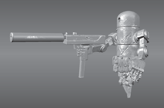
As mentioned before, Bertie is a robot from Ashley Wood's various comic books and paintings. Even though I have all the books that his images are in, an Internet search also found collectible action figures of Bertie and various images of those action figures. I first created a reference folder of all the images I found. I also spent a good amount of time looking at the comic books, reading the stories, and thinking up scenarios that Bertie would be in.
Then, I thought of real-world materials and the wear and tear a robot like Bertie would manifest. I did a search for images of WWII tanks, metal barrels, and mechanical robots in extreme conditions and came up with some surfaces that I liked. I then determined the number and nature of paint layers I would need. I envisioned three distinct materials on my model of Bertie: the metal that makes up his body, the leather pouches, and the metal that makes up his gun.
I also determined that I would be working with four diffuse paint layers and one specular layer. The four paint layers would be as follows:
Base coat layer This would be the metal base that Bertie is made from. Through my research, I found that big lumbering machines are made of galvanized metal sheets that are cut and bent into shape. Doing research on the Web and using Photoshop, I made a tileable galvanized metal texture (included as galvanized_steel_tileable.tga on the DVD in the Stencils folder). The Web has multiple tutorials on how to make tileable textures in Photoshop and other applications. As the paint would scratch off Bertie, this layer is what would show up underneath. This layer would mostly take care of the metal portions of Bertie, and I would paint the leather pouches a neutral leather color to set their base coat.
Paint layer The paint layer would include the basic color of Bertie's different parts. His body would be a dark greenish-gray, the leather pouches would be black, and the gun would be dark gray steel.
Weathering layer This would be the grime, rust, and wear-and-tear layer.
Decal This layer would include all the spray-painted or glued-on insignia and stickers.
I also planned to include a specular layer that would distinguish between the various specularity areas of Bertie's body, gun, and leather pouches.
To start, you will make the base coat layer, which is the galvanized metal that will show up through scratches on the edges or when paint is scraped off.
You will be using two paint tools in this first section to create the base coat layer. They are the Paint Brush and the Projection tool:
Paint Brush This is the standard workhorse painting brush. It uses the chosen stamp and color to paint on the surface of your model. The Strength setting controls the opacity of your stroke. You can adjust the various properties to get the effects that you want with your stroke.
Projection tool This is one of the most useful and powerful tools in Mudbox. It allows you to paint portions of your stencil image onto the surface of your 3D model. It is useful for painting real-world textures from digital photos and images right onto the surface of your model. Make sure to retain the relationship of the stencil and the zoom level of your model. What you projection-paint is the exact representation of the stencil on the surface of the model at the zoom level at which you are on the model. For example, if you zoom out on the model so it is small on the screen and projection-paint on it, when you zoom back in, you will lose the detail of your stencil and get a distorted and blocky texture. This is because at that zoom level, you didn't paint enough texture information on the surface to account for the details of the stencil. Make sure you are projection-painting the stencil at the detail level that relates to the zoom level of your model, and refrain from zooming in and out to maintain the scale of your stencil on the surface.
To create the base coat layer, follow these steps:
Either load your last saved version of Bertie, or load the
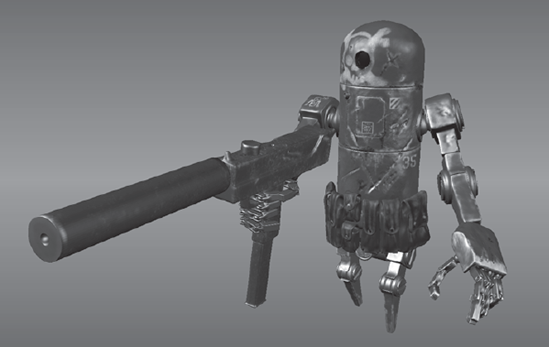
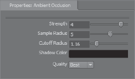
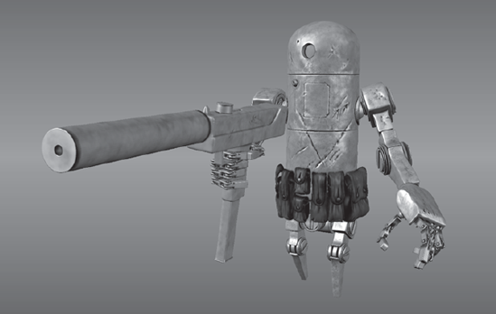
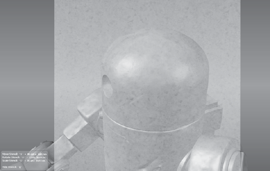
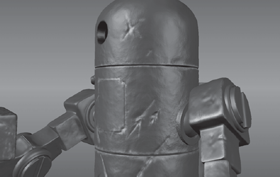
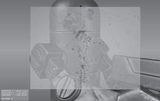
bertie_stage_06.mudfile from the Chapter 4 folder from the DVD. This is my final project file for this chapter (Figure 4.3).Tumble the camera around and observe the various surface details on Bertie. Click the Viewport Filters tab and turn on Ambient Occlusion by clicking the circle to the left of it in the display column with an icon of an eye as the column heading. This darkens the various crevices to give the model surface a more realistic look. I will be going into depth as to what the settings are for the Ambient Occlusion viewport filter in Chapter 9, "Lighting and Rendering," but for now, choose a Strength setting of 4, a Sample Radius setting of 5, and a Cutoff Radius of 1.16. Leave Shadow Color blank, and choose a Quality setting of Best (see Figure 4.4) because it will render a better view of Bertie for you to look at. Note the various surface details.
You will be going through the steps in this chapter to create your own version of a painted Bertie, but in the interest of saving space on the DVD to include more information for you, I unfortunately need to put you through a few extra steps of loading the final version and subtracting out layers and steps to get to the beginning of the stage. From the Select/Move Tools tray, click the Objects selection tool and click on any part of Bertie. After he is selected, click anywhere outside Bertie in the 3D view to remove the highlight. This will leave Bertie selected. In the Layers tray, click the Paint button and notice the five paint layers. Starting with the diffuse group, start from the top and click the little dot next to each one of the diffuse paint layers to hide them until you get to the
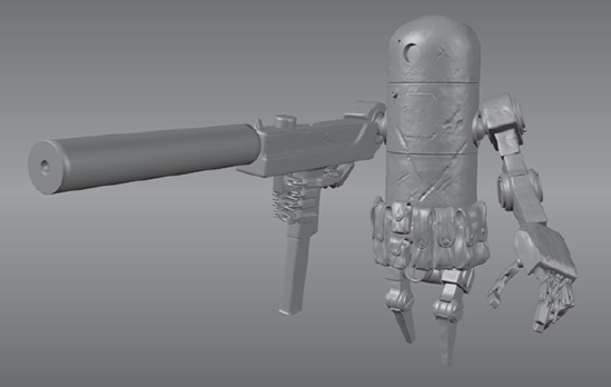
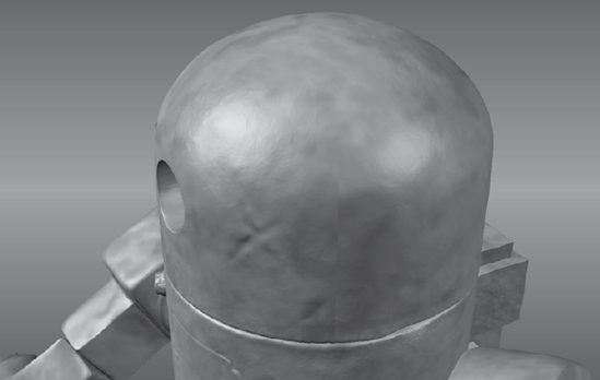
base_coatlayer (Figure 4.5). It is a pretty convincing paint-stripped metal robot. Now turn off the specular layer to see how much of the realism disappears.In the Layers tray, right-click each of the paint layers and select Delete Selected from the menu. This might take a little bit of time while Mudbox processes each of the deletions, but it is unfortunately necessary to save room on the DVD for the material in the book. Then, turn off Ambient Occlusion in the viewport filter to get back to the original Bertie sculpt that you did in the preceding chapter (Figure 4.6). Save the scene just in case you need to start back from this stage and don't want to go through deleting all the layers. I have done a little bit more surface detailing using the process familiar to you from Chapter 3, "Detail-Sculpting an Imported Model," of using the Spray tool from the Sculpt Tools tray and a stamp. In this case, I used the
bw_clifface.tifstamp to add more of a rough surface to Bertie after seeing pictures of tanks that had the same painted metal effect.For the material, leave everything as the default Mudbox material. You could change the color of your material to white, but it will not make any difference after adding the texture layers.
You are now at the starting point and need to add the base coat to Bertie. You could paint on the base coat, but it is easier to import a tileable texture of galvanized metal. I created this one in Photoshop by using some references and various filters, and then using the Offset filter. You can find numerous free tutorials online explaining how to make a texture tileable in Photoshop. The result of my work is shown in Figure 4.7, which I have supplied for you on the DVD. To import a tileable texture, go to the Layers tray and click the Paint button. From the Layers tray's window menu, click Import Layer. From the DVD
Stencilsfolder, selectgalvanized_steel_tileable.tgato load it as a paint layer. Double-click the name of the layer and type in the name base_coat.For the most part, the tileable layer covers most of your model pretty well, except for some seams (Figure 4.8). To get rid of the seams, you will use the same texture as a stencil and paint over the seams.

Next, you will scale the stencil to match what you have on the model. Notice the help messages on the bottom left of the screen. Click and hold down S on the keyboard and right-click and drag to scale up the image. Scale it up so it roughly matches the texture on the robot in Figure 4.9. Click the Projection tool in the Paint Tools tray and paint over the seam. Because this pattern is so random, this works really well to hide the seams. Press Q to hide your stencil and examine your work. Notice that you have very easily gotten rid of the seam. Do the same for all the other seams that you feel stand out on the model. There are four on the head, one on the parts of the center body, and many on the edges of the arms. Do this for practicing projection painting, but don't worry about getting every seam because most of this layer will remain hidden. When you are finished, click on the Stencil tray and click Off to turn off your stencil.
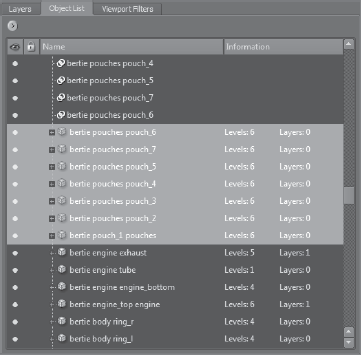
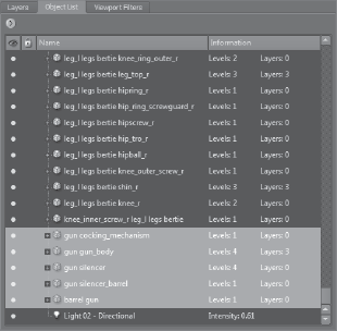
You now will put a different base coat on the ammo pouches because they are not made of metal. First, you will need to hide everything but the pouches to make it easier to work on them and not affect the rest of the model. In the Object List, select all the pouches either by clicking on the topmost pouch and then holding down the Shift key and clicking the bottommost pouch, or by holding down the Ctrl key and clicking each pouch in the Object List (Figure 4.10). As you select the pouches, they become highlighted with a yellowish sheen in the 3D View.
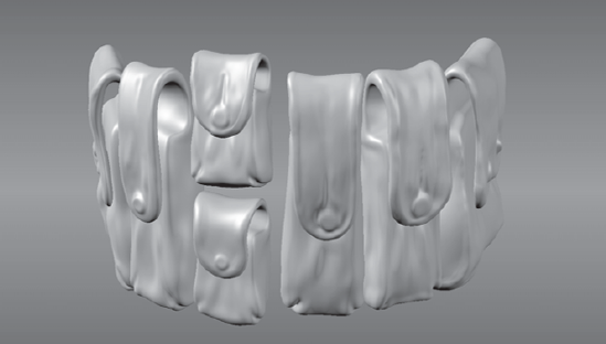
Choose Display → Hide Unselected to hide the rest of Bertie and to display just the pouches (Figure 4.11). From the Select/Move Tools tray, click the Objects selection tool and click anywhere in the 3D view to deselect the pouches.
From the Paint Tools tray, select the Paint Brush tool. In the Properties tray for the Paint Brush tool, pick a dark gray or dark green color. With a large brush size and strength of 100, quickly apply uniform paint to the pouches.
Press U or choose Display → Show All to redisplay all of Bertie.
Save your work. Then right-click the
base_coatpaint layer in the list of Paint Layers and click Export Selected from the drop-down menu. Save the file as base_coat.tga.
The next layer to be painted on is the paint layer. This will include the paint that is applied to Bertie, his gun, and his leather pouches. You will also strip away some of the paint in areas that could be scratched to reveal the galvanized metal beneath it. You will again block in the major swaths of paint and then texture the gun and pouches afterward.
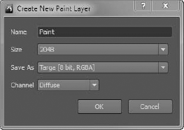
Click the Layers window drop down menu and select New Layer from the drop-down menu. Create a new diffuse paint layer with a size of 2048 × 2048 (2K) and use the Save As Targa [8 bit, RGBA] format (
.tga). Call itpaint(Figure 4.12).Right-click the layer you just created and click Export Selected. Export it as
paint.tga. Now right-click it again and click Delete Selected. You could have skipped this step and just created your image in Photoshop, but this process automatically creates an alpha channel for you.Load the
paint.tgafile into Photoshop or your favorite 2D painting application and fill it with a uniform military dark gray-green or any other color of your choice and save it back out as a 24-bit.tgafile. You can alternately use thecamo.tifcamouflage pattern I have supplied in theStencilsfolder on the DVD. However, you will have to use the same technique we used with the galvanized metal texture to projection-paint the camo pattern on the seams.Click the Layers window drop down menu, click Import Layer, and re-import the
paint.tgafile. Make sure it imports on top of thebase_coatlayer.Select the Paint Brush tool and then a black color. Color the two holes on Bertie's head black.
Select the Paint Erase tool from the Paint Tools tray, and reduce the size to a small size such as 2 or 4, and select a strength of around 10. Choose the
bw_bristol2.tifstamp, and start erasing areas that you feel might have paint chipped or scratched off, such as the borders of the hatch, the insides of the scratched and gouged areas on the model's surface, the edges where Bertie's head and torso would turn, and the sharp edges of the arms, legs, and fingers (Figure 4.13).Look at references of paint chipping off tanks, tractors, and construction vehicles to get some ideas of how paint would chip or scratch off a painted surface. If you make mistakes, you can use Undo to go back a few steps, or you can delete the paint layer and re-import a pristine version of it. You may also want to save different versions of your paint layer by exporting texture map versions such as
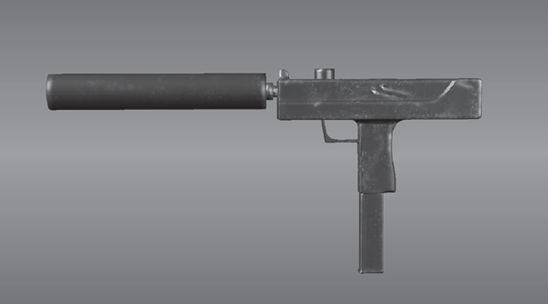
paint_slight.tgaorpaint_extreme.tga.When you are happy with your results, it is time to move on to the gun. Select all the gun parts in the Object List (Figure 4.14) and click Display → Hide Unselected. From the Select/Move Tools tray, click the Objects icon and click anywhere except on the gun in the 3D view to deselect the gun.

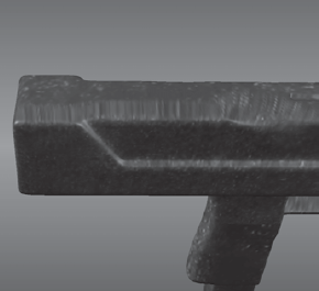
From the Paint Tools tray, select the Projection tool and start painting on the gun. Notice that as you paint on a surface that faces you, and your brush goes over the edges, you get streaks when you rotate the model (Figure 4.15).
This is overcome with two easy steps. First, make sure your brush fits on the surface you are painting and does not go over the edge. Then rotate the gun so that the top edge of the gun is facing you at an angle, as in Figure 4.15, and projection-paint on the angle. This is a good exercise for you to practice projection painting and not have any streaks because you will be working on flat, angular shapes as well as the cylindrical shape of the silencer.
Remember that you can move, rotate, and scale the stencil by holding down the S key and clicking and dragging with the middle, left, and right buttons of the mouse. You can also press the Q key to hide the stencil and view your model; another press of the Q key toggles the stencil back into view.
After you are finished applying the stencil as evenly as you can, it is time to paint over it with a dark gunmetal gray while letting some of the underlying details show. Pick the Paint Brush tool and a very dark gray color. Set your strength to about 2. Gently paint on top of the stencil pattern, letting bits and pieces of it show through to get a realistic metal finish (Figure 4.16).
Use the same process to color the leather pouches. Find a leather reference or shoot your own. Isolate the pouches by selecting them and hiding the rest of the model. Use your images as stencils and projection-paint the pouches.
Save your scene, and then right-click the paint layer in the list of Paint Layers and click Export Selected from the drop-down menu. Save it as
paint.tga.
In addition to using the Paint Brush and Projection tools, you also used the Paint Erase tool in this section.
Paint Erase is used to remove paint from the currently active paint layer. If a model has multiple paint layers, erasing paint on one layer reveals the visible layers below it.
For the weathering layer, you will add some more scratches, rust, dirt, and various other elements that would be the effects of a battle environment on Bertie. In this section, you will use two more painting tools, the Dry Brush tool and the Pencil tool. The only painting tool you will not use in this chapter is the Clone tool.
The Dry Brush tool is used to paint in areas that are either raised or recessed. By default, the Dry Brush tool paints protruded areas on your model; pressing Ctrl will paint recesses. The distance in from the top of a protruded area or the distance out from the bottom of a recessed area is controlled by the tool strength.
The Pencil tool is used to draw thin, sharp lines.
The Clone tool is similar to the Clone tool in Photoshop, which is used to sample paint on one area of a model and to apply it onto another area of the same model. To use the Clone tool, Ctrl+click the region you want the paint to be copied from. This sets the location of the starting point from which the Clone tool copies the paint. Then position the Clone tool where you want the cloned paint to appear and begin painting.
To create the weathering layer, follow these steps:
Click the Layers window drop down menu and select New Layer. Create a new diffuse paint layer with a size of 2048 × 2048 (2KB) and the Save As Targa [8 bit, RGBA] format (
.tga), and call itweathering.Use the Paint Brush tool to paint some dirt and scratches on Bertie.
Use the Projection tool and some of the rust textures in the
Stencilsfolder on the DVD to paint some rusty areas on Bertie (Figure 4.17). Use some of the references you gathered as a guide to paint some rust streaks and spots.Find some surface areas where water would pool or areas where leaks would have made the surface scratches and dents rust over time. Paint some rust on those areas (Figure 4.18). Based on the
Rust Stages.jpgimage in theChapter 4 eferencefolder, notice that rust has a more orange and light red color in deeper, fresher areas and gets more of a dull, dark, red sheen on the outer edges.Using the Dry Brush tool and a dark brown color, paint some dirt on areas that that have raised, sculpted surface patterns. This is a perfect brush to add a patina to your model.
Use the Pencil tool to draw fine lines to fill in scratches and areas where you want to add some fine detail.
Save your scene. Right-click the paint layer in the list of Paint Layers and click Export Selected from the drop-down menu. Save it as
weathering.tga.

For the decal layer, you will use 512 × 512 bitmaps as stencils and paint insignia on Bertie:
Click the Layers window drop down menu and select New Layer from the drop-down menu. Create a new 2K TGA paint layer and call it
Decal.In the Image Browser, navigate to the
StencilsDecalsfolder on the DVD. I have created 11 decals you can use on Bertie. These are simple.tifimage files with an alpha layer. You can load them in Photoshop to modify them. I have also included an empty template calleddecal_template.tifyou can use to paint on to create your own decals. You can also use this template to make a 512 × 512 stamp too.Pick a decal and set it as a stencil. Use the S key + left, middle, or right button combinations to scale, position, and rotate the decal.
Using the Projection tool, and the
bw_bristol2.tifstamp, gently draw out the stencil on the surface of the model. If you set your tool Strength to 3, you can apply the stencil in an additive way, which gives it a more realistic look.Save your scene, and then right-click the decal layer in the list of Paint Layers and click Export Selected from the drop-down menu. Save it as
decal.tga.
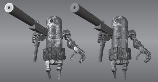
The specular layer is a grayscale image that specifies what degree of specularity our surface has. We can indicate which parts are shiny and which parts are not. As you can see in Figure 4.19, the image on the left has a specular layer, and the image on the right does not. The image on the left looks far more realistic.
Click the Layers window drop-down menu and select New Layer from the drop-down menu. Create a new 2KB TGA specular layer and call it
specular. You need to specify Specular as the channel in the Create New Paint Layer dialog box.Note that the specular channel is not in the same grouping as the diffuse layers.
In the interest of time, I imported the
galvanized_steel_tileable.tgaimage as the base specular layer, and used the Paint Brush tool to paint on areas that will be shinier by choosing light gray or white, and areas that will not be shiny with black.Because the robot and gun are of different metals, you can apply a different specular value to the gun than the rest of Bertie.
Notice that if we do a good job with the specularity, we will have a very realistic model, even if we turn the rest of the layers off (Figure 4.20).
Rusty areas are not specular, so make sure not to apply specularity to them. Some of the decals could be less or more reflective, so apply some specularity to them as needed.
Save your scene. Then right-click the specular layer in the list of Paint Layers and click Export Selected from the drop-down menu. Save it as
specular.tga.
Mudbox allows us to paint a specular map in real time so we can see the final results as we are working on the model.
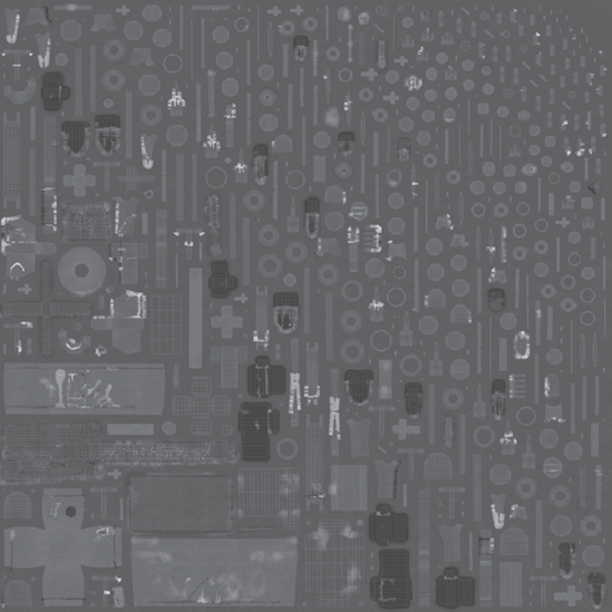
Now that you are finished texture-painting the model, you can take the textures into Photoshop for further manipulation. Load the Bertie_map_composite.psd file (Figure 4.21) into Photoshop and notice the various layers and their opacity. This would be a good place to paint details that you were not able to do in Mudbox, because Photoshop has numerous brushes and layer-compositing tools that you can manipulate to get the exact look you are going for.
In this chapter, you have gone through texture-painting an imported model of Bertie the robot. You have seen how critical a good UV layout and efficient UV shell distribution in UV space are to the texture-painting process. You have learned the difference between materials and textures and how you need to reverse-engineer the look of objects around you to determine their material properties and their texture layers.
You also have learned about paint and texture layers and their functions in Mudbox. You have seen how in Mudbox you can use opacity levels and layer order to control how layers are composited on top of one another. You have learned the importance of gathering and compiling reference material to aid in the modeling and texture-painting process. And finally, you texture-painted Bertie with various layers to get the final result.