


Installation and configuration
This chapter shows how to install and configure IBM FlashSystem V9000. The system environmental requirements, cabling, and management are described. Installation from the initial setup procedure through configuring the system for use is demonstrated.
This chapter includes the following topics:
6.1 Installation overview
Installation and initial configuration of IBM FlashSystem V9000 requires the completion of various tasks. An IBM Service Support Representative (SSR) installs a single building block without switches. All other configuration is done by IBM lab services. An SSR is responsible for the physical installation only. After this is done, the customer can then set up the system.
|
Important: The customer worksheets listed beginning in section 4.2.1, “Racking considerations” on page 117 must be completed before the installation, because they determine the location of the components in the rack.
|
6.1.1 Tasks for the IBM SSR or IBM lab-based services
During installation, the IBM SSR or the IBM lab-based services does the tasks described in this section. To learn about the steps that will be performed, limitations, and requirements, see the “Installing” topic at the FlashSystem V9000 web pages in the IBM Knowledge Center:
Hardware installation
To install the FlashSystem V9000 hardware, an IBM SSR or IBM lab-based services must complete the following tasks:
1. Install the AC2 control enclosures and AE2 storage enclosure in the rack.
2. Connect the components as planned using Fibre Channel (FC) either in a direct attach configuration or with FC switches for internal, and with switched fabrics for the host, the Ethernet management switch, and to the power distribution units.
3. Connect the components, using FC with or without switches, the Ethernet management switch, and connecting the components to the power distribution units:
– For a fixed building block (BB) installation, the SSR completes the cabling.
– For a scalable BB installation, IBM lab-based services completes the cabling.
|
Note: For details about the procedure to power up FlashSystem V9000, see the FlashSystem V9000 IBM Knowledge Center:
|
Initial setup tasks
After the hardware is installed in the rack and cabled to meet the configuration you want, an IBM SSR or IBM lab-based services conducts the initial installation and configuration by performing the following tasks:
1. Connect a workstation to an AC2 control enclosure Technician port.
2. Configure the V9000 clustered system with a name and management IP address.
3. Use the web browser to go to the management IP address of the cluster, and follow the steps of the setup wizard in the management GUI to set up call home using information from the customer-supplied worksheets, as shown in Chapter 4, “Planning” on page 111. Also complete the expansion enclosure and creation the MDisks.
4. If a scalable solution is being installed, an extra expansion or scalable building block is added to an existing system; the IBM SSR or IBM lab-based services logs in to the control enclosure management GUI and adds the new building block to the scaled system from the system page.
6.1.2 First customer involvement
After the IBM SSR or IBM lab-based services completes the service setup process, you log in to the AC2 control enclosure and complete the following tasks by using the customer setup wizard:
1. Change the system password.
2. Set the date and time.
3. Create I/O groups (if applicable).
4. Confirm the call home settings that the IBM SSR or IBM lab-based services entered.
5. Configure licensed functions.
6. Create storage pools.
At the completion of the setup wizard, the setup wizard creates storage arrays and assigns the MDisks on the AE2 storage enclosures to the storage pools.
6.2 IBM FlashSystem V9000 physical specifications
The IBM FlashSystem V9000 is installed in a standard 19-inch equipment rack. The IBM FlashSystem V9000 building block is 6U high and 19 inches wide. A standard data 42U 19-inch data center rack can be used to populate with the maximum FlashSystem V9000 configuration to use up to 36U. For a description of physical dimensions, see 2.2.4, “Physical specifications” on page 48.
6.3 Installing the hardware
The IBM SSR is responsible for physically installing FlashSystem V9000.
This process involves installing the two control enclosures and the storage enclosure. These three enclosures form a 6U building block. For a scalable building block, additional components, such as Fibre Channel switches and an Ethernet switch are also installed.
When installed, the components of the FlashSystem V9000 appear as shown in Figure 6-1. Only 8 Gbps Fibre Channel attachment can be used for direct attach.
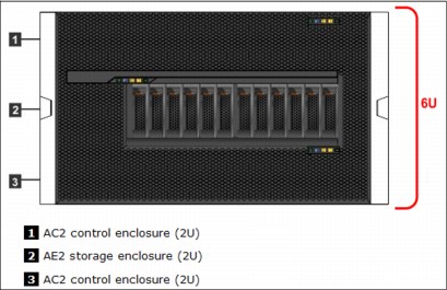
Figure 6-1 View of the FlashSystem V9000 front panel
6.4 Connecting the components
The AE2 storage enclosure and AC2 control enclosures can be connected to create a fixed building block or a scalable building block:
•The IBM Service Support Representative (SSR) is responsible for connecting (cabling) the three enclosures in a fixed building block.
•Lab-based services is responsible for cabling the AC2 control enclosures, the AE2 storage enclosure, and the Fibre Channel switches and Ethernet switch in a scalable building block.
The detailed interface protocol and connection diagrams for the following FlashSystem V9000 configurations are available in 2.1.6, “Protocol support” on page 31:
6.4.1 Connecting the components in a fixed building block
The IBM SSR is responsible for connecting the components of a fixed building block (BB).
To create a fixed building block, you create direct links between the AE2 storage enclosure and the two AC2 control enclosures, and also connect the hosts or external storage to the AC2 control enclosures.
To improve performance and provide redundancy, both AC2 control enclosures are connected to both canisters in the AE2 storage enclosure.
Figure 6-2 on page 191 illustrates the interface protocols and maximum number of connections supported for a FlashSystem V9000 fixed building block for a five-host, 8 Gbps Fibre Channel configuration. There are also redundant cluster links between the two AC2 control enclosures.
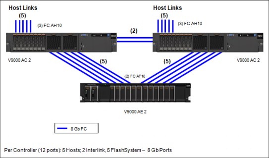
Figure 6-2 Fixed building block protocols and connections for 8 FC Gbps configuration
For more diagrams of supported protocols and connections for IBM FlashSystem V9000 fixed and scalable building blocks for following interface protocols, see “Fixed building block protocols and connections” on page 316.
|
Note: For the fixed BB 8 Gbps configuration, you need two FC ports (AC2 to AC2) and five FC ports (AC2 to AE2), the remaining five FC ports can be used for host or external storage attachment.
|
A sample cable connection table can be downloaded from the V9000 web page in the IBM Knowledge Center by using the following steps:
1. Go to the following web page:
2. Click the Planning topic in the Table of Contents.
3. In the Planning section, select Planning for the hardware installation (customer task).
4. Click Planning worksheets for fixed building blocks.
6.4.2 Connecting the components in a scalable building block
IBM lab-based services is responsible for cabling the building block components.
Cabling involves installing the network and storage data cables that are internal to the IBM FlashSystem V9000 scaled building blocks.
Figure 6-3 shows a conceptual view of a typical cabling example of one building block with an added AE2 storage enclosure.
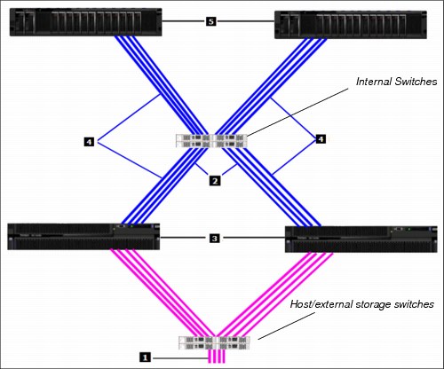
Figure 6-3 One building block and one additional AE2 storage enclosure connection
The numbers in the figure have the following meanings:
1. Host and external storage connections
2. Redundant cluster links between the AC2 control enclosures
3. AC2 control enclosures
4. Fibre Channel connections to the AE2 storage enclosures
5. AE2 storage enclosures
Remember that one building block contains two AC2 control enclosures and one AE2 storage enclosure. Your final configuration can be up to four building blocks and four additional AE2 storage enclosures.
For internal Fibre Channel switches, a minimum of two switches are needed for redundancy purposes on a 16 Gbps configuration and four switches for an 8 Gbps configuration. Switches that IBM suggests can be used, or any other switches can be used with the relevant attention on the open access method that is used by the AC2 control enclosure to reach the AE2 storage enclosure.
Host connections to the AC2 control enclosures can be these connections:
•Direct/switched Fibre Channel connections (16 Gbps or 8 Gbps)
•Fibre Channel Over Ethernet or ISCSI (10 Gbps Ethernet links)
The rear view of the AC2 control enclosure is shown in Figure 6-4.
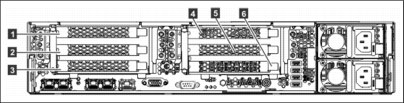
Figure 6-4 AC2 controller enclosure rear view
For more details about interconnecting the cables to the AC2 control enclosure and to the AE2 storage enclosure in a scalable configuration, see Chapter 2, “FlashSystem V9000 architecture” on page 19 and see “Scalable building block protocols and connections with 8 Gb interconnect fabric” on page 32.
A sample cable connection table can be downloaded from the IBM FlashSystem V9000 pages in the IBM Knowledge Center by using the following steps:
1. Go to the following web page:
2. Click the Planning topic in the Table of Contents.
3. In the Planning section, select Planning for the hardware installation (customer task).
4. Click Planning worksheets for scalable building blocks.
For comprehensive examples and configuration guidelines on the following two preferred methods for port utilization in a FlashSystem V9000 scalable environment, see Appendix A, “Guidelines: Port utilization in an IBM FlashSystem V9000 scalable environment” on page 557:
•FlashSystem V9000 port utilization for infrastructure savings
This method reduces the number of required customer Fibre Channel ports attached to the customer fabrics. This method provides high performance and low latency but performance might be port limited for certain configurations. Intra-cluster communication and AE2 storage traffic occur over the internal switches.
•FlashSystem V9000 port utilization for performance
This method uses more customer switch ports to improve performance for certain configurations. Only ports designated for intra-cluster communication are attached to private internal switches. The private internal switches are optional and all ports can be attached to customer switches.
Following the cabling guidelines in this appendix, for the FlashSystem V9000 port utilization for performance method, can result in performance improvements up to 40% for sequential reads and up to 80% for sequential writes.
6.4.3 Ethernet cabling
IBM lab-based services is responsible for cabling components to the Ethernet switch.
The internal connectivity Ethernet switch provides management connections for the FlashSystem V9000.
Figure 6-5 shows a typical wiring diagram for cabling the components to the Ethernet switch.
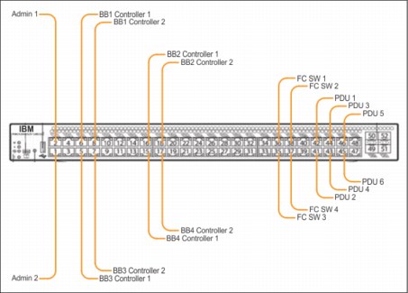
Figure 6-5 Ethernet switch wiring diagram
Switch port usage depends on the speed:
•If two 16 Gbps FC switches are used rather than four 8 Gbps FC switches, only two of the four Ethernet connections for FC switches are needed.
•Redundant Ethernet management links for AC2 control enclosures are not necessary to protect them from management link and port failures. The AC2 control enclosures function as a pair in an I/O Group, and, if there is a node failure, the partner AC2 control enclosure in the I/O group (or another AC2 control enclosure in the cluster) takes over management of the I/O group or cluster.
6.4.4 Scaling from one to two, three, or four building blocks
IBM lab-based services is responsible for the configuration tasks that are involved in scaling from one scalable building block to two, three, or four scalable building blocks.
Before you begin
Be sure these actions are complete before you scale the environment:
•The building block components must be installed in the rack in the specified locations.
•The building block components must be cabled.
•The first scalable building block must be operational.
Procedure
Follow this procedure to add a new building block:
1. Power on the components for the new building blocks.
2. Log on to the management GUI of the existing system. The system recognizes that there are new candidate enclosures and displays a graphic that shows the new enclosures.
3. Place the cursor over the graphic of a new enclosure, and then click to run the wizard that adds the new enclosure to the system.
4. When adding more flash capacity, the wizard prompts you to select whether to configure the storage for maximum performance or maximum availability:
– Maximum performance places all of the flash memory enclosure’s capacity into a single pool, causing volumes to be striped across all enclosures, and providing maximal performance. If a single full flash memory enclosure failure occurs, the whole storage will be offline.
– Maximum availability creates one pool (managed disk group) per flash memory enclosure. Each pool is then scoped to the specific enclosure, which creates a failure domain. If a catastrophic failure of one enclosure occurs, only one pool is affected.
5. From the networking section of the GUI, add the management IP addresses for the new building blocks. For details, see 4.3.1, “Management IP addressing plan” on page 125.
For more information about various interface setups, see Appendix A, “Guidelines: Port utilization in an IBM FlashSystem V9000 scalable environment” on page 557.
6.5 Initial customer setup
After the service setup of the new system is complete, you can use the management GUI to input the initial setup information.
Before you begin, be sure that you have the following information:
•The cluster management IP address of the system entered by the IBM SSR
•The IP address of a Network Time Protocol (NTP) server, for automated setting of date and time
•Licensed function information
•The Single Mail Transfer Protocol server IP address
•Any email contacts you want to be added in the notification mails
6.5.1 License agreement and password change
This section explains how to start the customer setup wizard.
|
Tips: Later, you will need the cluster management IP address (<management_ip_address>) that the IBM SSR entered.
|
Complete the following steps:
1. Open a supported browser and go to the following address:
http://<management_ip_address>
2. To continue, read and accept the FlashSystem V9000 product license (Figure 6-6).
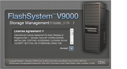
Figure 6-6 License agreement page: click Accept
3. After accepting the license, enter the current password (passw0rd with a zero in place of the letter “O”) and click the Log in arrow (Figure 6-7).
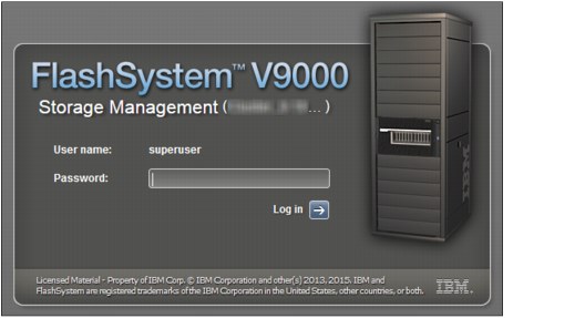
Figure 6-7 Login page
4. You can change the password in the next window (Figure 6-8).
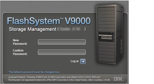
Figure 6-8 Superuser password change panel
6.5.2 System Setup wizard
This section guides you through the configuration wizard, see start page (Figure 6-9 on page 198).
You might need the following information (if the IBM SSR has not yet entered it):
•IP address of an NTP server
•IP address of the Single Mail Transfer Protocol server
|
Note: If the IBM SSR entered this information in the initial GUI, these values are displayed and you can verify them.
|
You will need the following information:
•Licensed function information
•The email and contacts you want to be added to the “notification mails”
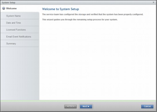
Figure 6-9 First wizard panel, click Next
6.5.3 System name change
You can change the system name by completing the following steps:
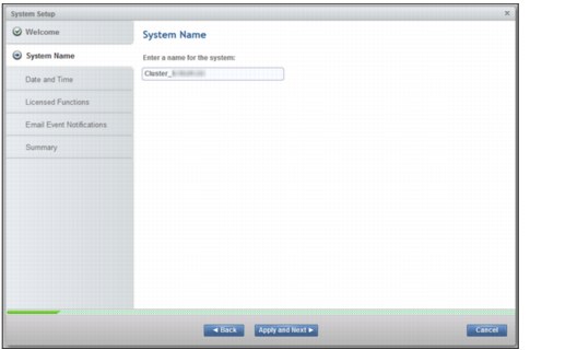
Figure 6-10 System Name change
2. The next window displays the result of the System Name change. On error, you can click Cancel, or Close to continue (see Figure 6-11).
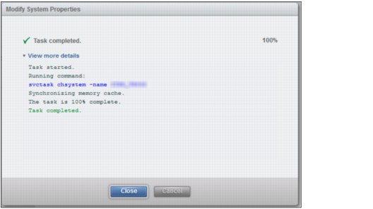
Figure 6-11 System Name change completion window
6.5.4 Date and time setup
In the next step, you set the date and time. The two options are as follows:
•Enter the date and time manually or based on an external NTP server.
•Synchronize the logs with all others systems using the same NTP server. This is the preferred option.
|
Note: If during the initial setup, the IBM SSR entered any information, you can validate the information by clicking Apply and Next.
|
Depending on your time and date selection, you see two separate pages (Figure 6-12 and Figure 6-13).
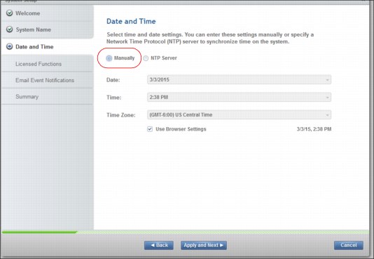
Figure 6-12 Manual time and date setting (not preferred selection)
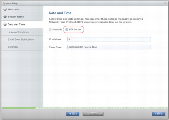
Figure 6-13 Time and date using an NTP server (preferred selection)
The next window shows the results of the date and time change (Figure 6-14). On error, you can click Cancel, or click Close to continue.
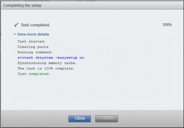
Figure 6-14 Date and Time change completion window
6.5.5 Licensed functions
To provide the correct values for the licensed functions (Figure 6-15), refer to the licenses feature code that you purchased. Select the Encryption check box to start the encryption wizard after you complete the Licensed functions wizard. For more details about setup and configuration for encryption, see 9.4.2, “Encryption” on page 371.
|
Note: Enter only the purchased values of licensed functions. Inaccurate licensed functions data can compromise the IBM support response.
|
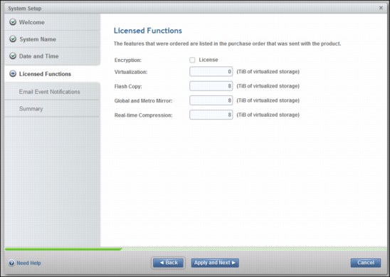
Figure 6-15 Licensed functions
6.5.6 Email Event Notifications
Email Event Notifications is the final step. If the IBM SSR already entered the system location and the email server, validate the data and alter the values if not correct. Figure 6-16 shows the main panel.
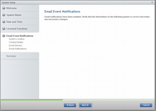
Figure 6-16 Email event notifications, click Next
Validate or enter the system location (Figure 6-17).
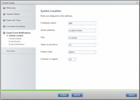
Figure 6-17 Physical system location
In the Contact Details (Figure 6-18 on page 205) page, validate or set the person who will resolve issues on the system.
|
Tip: The value in the Email address field will be used by the FlashSystem V9000 to send email messages for heartbeat, call home, or events. This address must be authorized by your SMTP server. Usually a “while list” mechanism is the way to do this. Be sure to involve the SMTP support team when you set up the value in the Email address field.
|
Other information (Figure 6-18) is used by the IBM support team to contact your support team, so be sure that the information is accurate.
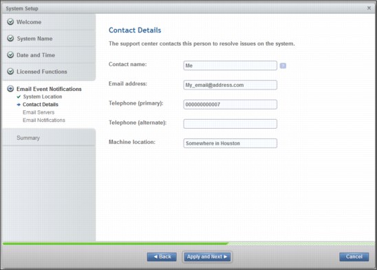
Figure 6-18 Contact Details
Validate or enter the information about the Email Servers (SMTP server IP address) page (Figure 6-19). You can add more than one server by clicking the plus sign (+) button.
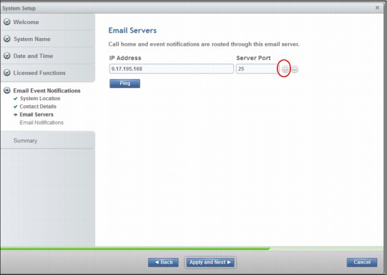
Figure 6-19 Email Servers (SMTP IP address)
Add any person who needs to be aware of events that are raised by IBM FlashSystem V9000.
As shown in Figure 6-20, you can select the levels of detail you want to see. The best approach is to start with the default values and then add details if needed.
Click the plus sign (+) button to add email addresses.
|
Note: The first email address is the IBM service center address. Be sure that the SMTP server allows email messages to destination addresses. Your SMTP support team might be able to check this. The automatic call home uses this address to trigger IBM intervention on your system. This address is periodically tested using the heartbeat.
|
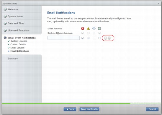
Figure 6-20 Email Notifications addresses
6.5.7 Summary of changes
The initial setup is now completed. Figure 6-21 shows a summary of all data. Read the summary information carefully. You can click Back to correct data, or click Next to validate the data.
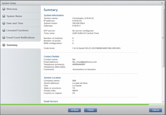
Figure 6-21 Summary of all changes
6.5.8 Encryption setting
To set encryption, complete the following steps:
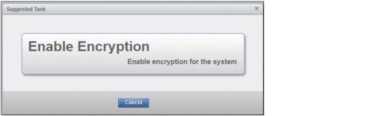
Figure 6-22 Encryption startup wizard
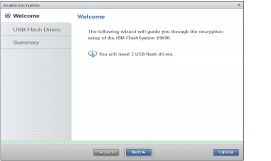
Figure 6-23 Locate 3 USB flash drives and select Next
3. Insert the IBM USB keys into the system, as shown in Figure 6-24. Use two keys in one node and one key in the other; the extra key will be removed later.
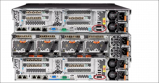
Figure 6-24 Insert the IBM USB keys into the AC2 Controllers
4. As shown in Figure 6-25, USB key count increments (1) as each key is inserted; when the keys are created click Next (2).
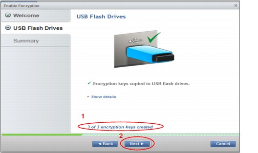
Figure 6-25 Create the Encryption keys
|
Tips: Remove one of the USB keys and store it in a safe place. If security policies allow, leave the two remaining keys in the control enclosure so they are available if the storage enclosure restarts.
Remember, if the encryption keys are not present, storage enclosure reboot is not possible.
|
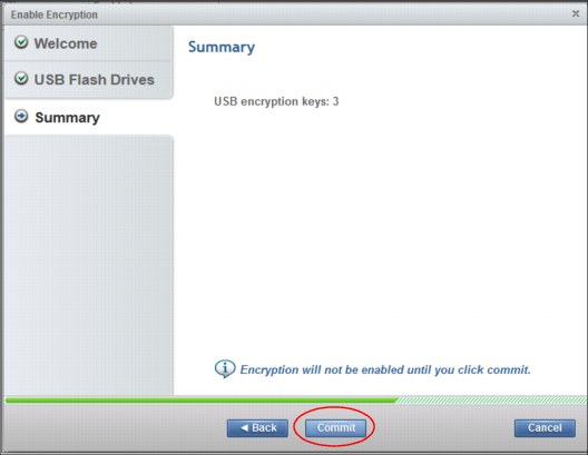
Figure 6-26 Commit to make the encryption effective
6. The confirmation information (Figure 6-27) indicates that the AE2 storage enclosures are now encrypted. Click Close to continue.
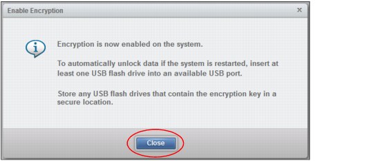
Figure 6-27 System is now encrypted
..................Content has been hidden....................
You can't read the all page of ebook, please click here login for view all page.