


Configuring settings
The Settings section of the IBM FlashSystem V9000 graphical user interface (GUI), as shown in Figure 9-1 on page 340, is described in this chapter. The Settings function covers various options for monitoring, configuring network interfaces, and extracting support logs. It also covers remote authentication and the firmware update process.
This chapter includes the following topics:
9.1 Settings menu
You can use the Settings panel to configure system options for event notifications, security,
IP addresses, FC connectivity, and preferences related to display options in the management GUI.
IP addresses, FC connectivity, and preferences related to display options in the management GUI.
The Settings menu includes five options:
•Notifications (alerting)
•Network (management and service)
•Security (remote authentication with Lightweight Directory Access Protocol (LDAP))
•System (time settings, firmware update, and so on)
•Support (extract support logs)
•GUI Preferences (customize the GUI)
9.1.1 Opening the Settings menu
Hover the cursor over the Settings function icon to view the Settings menu (Figure 9-1).

Figure 9-1 Settings menu
9.2 Notifications menu
FlashSystem V9000 can use Simple Network Management Protocol (SNMP) traps, syslog messages, and call home email to notify you and IBM Support when significant events are detected. Any combination of these notification methods can be used simultaneously.
9.2.1 Email and call home
The call home feature transmits operational and event-related data to you and IBM through a Simple Mail Transfer Protocol (SMTP) server connection in the form of an event notification email. When configured, this function alerts IBM service personnel about hardware failures and potentially serious configuration or environmental issues.
Configuration process
Setting up call home involves providing a contact that is available 24 x 7 if a serious call home occurs. IBM support strives to report any issues to our clients in a timely manner; having a valid contact is important to achieving service level agreements.
The procedure for configuring call home is similar to the initialization of the IBM FlashSystem V9000, which also offers configuration of email event notifications. The initial system setup is described in 6.5.2, “System Setup wizard” on page 197.
The steps to enable call home are to configure the following information:
•System Location: Where is the system located?
•Contact Details: Who is IBM to contact in case of call home?
•Email Servers: What is the IP address of the SMTP email server?
•Email Notifications: Who else requires notification through email?
This procedure assumes call home was not configured during initial installation. The procedure to update contact information or add extra notifications is basically the same. Simply edit the notifications.

Figure 9-2 Select Notifications
2. If call home is not set up, the pop-up area opens (Figure 9-3). Initiate the configuration wizard, by clicking Enable Notifications.
. 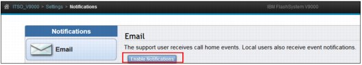
Figure 9-3 Enable Notifications
3. The Email Event Notifications wizard starts (Figure 9-4). It briefly describes the benefits of call home. Read through it and then click Next.
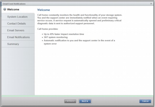
Figure 9-4 Configuring Call home enables IBM to provide excellent service
4. System Location panel (Figure 9-5) is important for ensuring that any open support tickets have the correct equipment location. Complete the form and click Next.
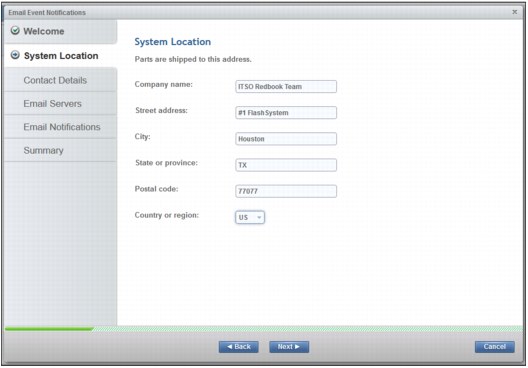
Figure 9-5 System Location panel
|
Note: The State or province and Country or region fields must be configured correctly to ensure that IBM support is able to react on call home calls from the system. Hover the cursor to the right of State or province field, and click the window that displays these codes.
|
5. On the Contact Details panel (Figure 9-6) specify a contact available 24 x 7. We must be able to reach a valid contact if an urgent situation exists. Click Apply and Next.
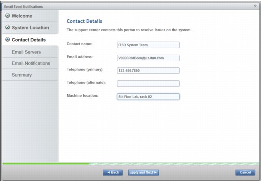
Figure 9-6 IBM support uses this contact 24 x 7
6. The Configuring Email Settings panel (Figure 9-7) shows the results. It also shows the CLI version of the dialog. Click Close.
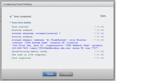
Figure 9-7 Commands run to register the contact and send inventory every 7 days
7. Enter your SMTP gateway IP address (Figure 9-8). You can click Ping to ensure that there is a response to the address. Click Apply and Next to move to the next panel.
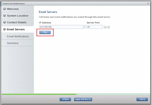
Figure 9-8 Specify and test the SMTP Gateway
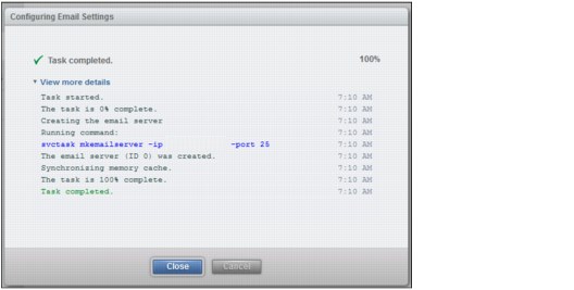
Figure 9-9 SMTP Gateway for all email is defined
9. Optional: You can configure event notifications to additional email recipients. An email notification to IBM Support is automatically configured, but normally clients prefer to be notified if issues occur that need attention.
Client event notifications are valuable if email transport to IBM fails. An email transport error can occur in an SMTP server outage, or if the SMTP server IP address is changed without the call home function of the IBM FlashSystem V9000 being updated correctly.
See Figure 9-10. Enter any additional users for email notifications (1). You can use the plus sign (+) or minus sign (-) operators (2) to manage the list.
|
Tip: You can tailor the types of notifications that you want to receive by using the check boxes. Hover over the icons to see what type of notification it is.
|
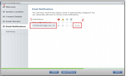
Figure 9-10 Email notifications are configured here; this page can be edited later
10. Review the summary page information that you entered in the wizard (Figure 9-11).
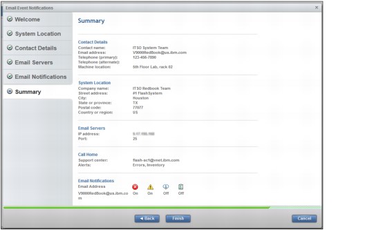
Figure 9-11 Completed call home setup
11. Review the command results, which are displayed in the Configuring Email Settings window (Figure 9-12). It indicates that the mail service started. Click Close.
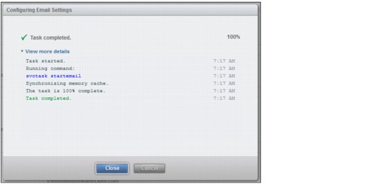
Figure 9-12 Results of starting the email service
12. After the wizard completes, you are returned to the notifications Email page (Figure 9-13). You see the same settings. Click Edit (1) to enable and select Test (2) in the Call Home section. This automatically sends a call home to IBM and create a problem management record (PMR). IBM support uses the primary contact to confirm receipt of the call home.
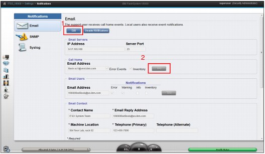
Figure 9-13 Use edit mode to test call home
|
Tip: Testing call home is important to ensure that the system is correctly registered with IBM. Test call home by submitting an Email Notification test after the Event Notification wizard finishes. If configured correctly, IBM Support will contact you during regular business hours.
|
9.2.2 SNMP
Simple Network Management Protocol (SNMP) is a standard protocol for managing networks and exchanging messages. The system can send SNMP messages that notify personnel about an event. You can use an SNMP manager to view the SNMP messages that the system sends.
In the SNMP configuration menu, you can configure one or more SNMP servers. For each of these SNMP servers, you configure the following information:
•IP address
•SNMP server port (The default is port 162.)
•SNMP community (The default is public.)
•Event type (The default is Alerts but it can be changed to All events.)
As shown in Figure 9-14, do these steps:
1. Select the SNMP tab.
2. Select Actions → Add.
3. Complete the details in the Add SNMP Server form that opens.
4. Click Download MIB to download the Management Information Base (MIB) file.
This MIB file is used for SNMP to configure a network management program to receive SNMP messages that are sent by the system. This file can be used with SNMP messages from all versions of the software.
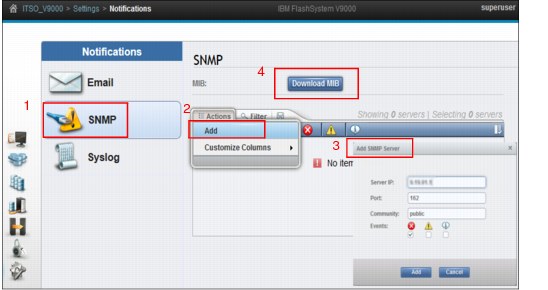
Figure 9-14 Add the SNMP Servers
Various SNMP trap receiver products are on the market. These are known as SNMP managers. IBM Tivoli NetView® or IBM Tivoli Enterprise Console® can be used as IBM SNMP managers.
9.2.3 Syslog
The syslog protocol is a standard protocol for forwarding log messages from a sender to a receiver on an IP network. The IP network can be either IPv4 or IPv6. The system can send syslog messages that notify personnel about an event.
The IBM FlashSystem V9000 can transmit syslog messages in either expanded or concise format.
As shown in Figure 9-15, you can do these tasks:
1. Use a syslog manager to view the syslog messages that the system sends. The system uses the User Datagram Protocol (UDP) to transmit the syslog message.
2. Specify up to a maximum of six syslog servers using the plus sign (+).
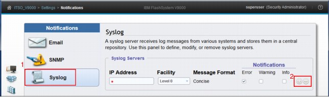
Figure 9-15 Complete the Syslog Form
In the Syslog configuration section (Figure 9-15), you can configure one or more syslog servers. For each of these servers, you configure the following information:
•IP address.
•Facility: This determines the format for the syslog messages and can be used to determine the source of the message.
•Notifications: The default is Alerts/Error but it can be customized to show Warning and Informational Notifications also).
There are various syslog server products on the market. Many of these products are no-charge products that can be downloaded from the Internet.
9.3 Network
Select Network from the Settings menu (Figure 9-16) to manage the management IP addresses for the system, service IP addresses for the nodes, Ethernet, and Fibre Channel configurations.
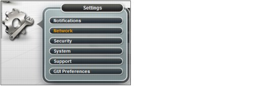
Figure 9-16 Select Network from the Settings menu
9.3.1 Management IP address
One Management IP address is defined when the system is initialized. The system supports multiple IP addresses to manage interfaces, such as the GUI and the CLI for the system. On the Settings > Network page (Figure 9-17), select Management IP Addresses. The current selection is outlined the figure.
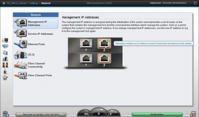
Figure 9-17 Change Management IP address or add a redundant address
9.3.2 Service IP addresses
On the Settings → Network page, the Service IP Addresses (Figure 9-18) are used to access the service assistant tool, which you can use to complete service-related actions on the node. The system has two nodes and each must have a different service address. If a node is in the service state, it does not operate as a member of the system.
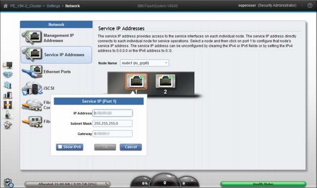
Figure 9-18 Set Service IP addresses for each node
|
Tip: Connecting Ethernet to the storage enclosure is optional. FlashSystem V9000 storage enclosures can be managed through the Service Assistant described in Chapter 10, “Service Assistant Tool” on page 399.
|
9.3.3 Ethernet ports
Ethernet ports for each node are on the rear of the system and are used to connect the system to iSCSI-attached hosts, and to other systems that are part of remote-copy partnerships. The Ethernet Ports panel indicates whether a specific port is being used for a specific purpose. You can modify how the port is used by selecting Actions → Modify.
Use the Ethernet Ports panel (Figure 9-19) to display and change how Ethernet ports on the system are being used.
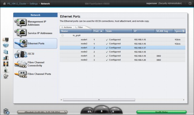
Figure 9-19 Examine Ethernet port connections to the controller
Change settings for Ethernet ports
For each Ethernet port, a maximum of one IPv4 address and one IPv6 address can be designated. Each port can be simultaneously used for remote copy over IP and as an iSCSI target for hosts. You can also configure Ethernet ports exclusively for remote copy. If you are using remote copy between a local and remote system using Ethernet ports, you must specify which ports are used for remote copy operations by creating a remote copy group.
The remote copy group indicates the set of local and remote Ethernet ports that can access each other through a long-distance IP connection. For a successful partnership to be established between two systems, the remote copy group must contain at least two ports, one from the local system and the other from the remote system. You can configure more than two ports from the same system in the remote copy group to enable IP connection failover if either the local or remote system experiences a node or port failure.
Modify IP address
To change the IP address of an Ethernet port select the port and click Actions → Modify IP Settings. The resulting dialog is shown in Figure 9-20 on page 353.
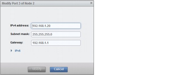
Figure 9-20 Modify IP address for a port
Modify iSCSI hosts
iSCSI is enabled for IPv4 as default for each Ethernet port with a configured IP address. iSCSI can additionally be enabled and disabled for both IPv4 and IPv6. To enable or disable iSCSI for a port from the Settings → Network menu click Actions → Modify iSCSI hosts. The resulting dialog is shown in Figure 9-21.
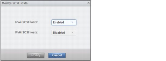
Figure 9-21 Enable or disable iSCSI for a port
Modify remote copy
The following leading practices apply to setting up IP partnerships:
•If you have one inter-site link, configure one remote-copy port group.
•If you have two inter-site links, configure two remote-copy port groups.
•If you have one remote-copy group, configure at least one port from each node in one I/O group in that remote-copy port group. For systems with more than one I/O group, add ports from a second I/O group to the remote-copy group.
•If you have two remote-copy groups and one I/O group, configure one port on each system from one node in the first remote-copy group, then configure a port from the other node in the second remote-copy port group. For systems with more than one I/O group, add ports from a second I/O group to each of the two remote-copy groups.
|
Note: No more than two inter-site links or remote-copy port groups are supported.
|
To enable or disable iSCSI for a port click Actions → Modify Remote Copy. Configure the Ethernet port for remote copy Group 1. The resulting dialog is shown in Figure 9-22.
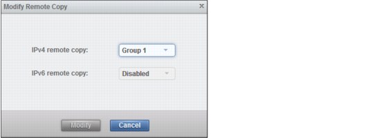
Figure 9-22 Modify Remote Copy
When remote copy has been configured on both systems and when they can communicate, a partnership can be configured and remote copy can be configured and enabled.
For more information about configuring remote copy and partnerships, see the following IBM Redbooks publication:
Implementing the IBM System Storage SAN Volume Controller V7.4, SG24-7933
Modify VLAN settings
VLAN tagging is a mechanism used by system administrators for network traffic separation at the Layer 2 level for Ethernet transport. Although network traffic separation can be configured at the layer 3 level using IP subnets, VLAN tagging supports traffic separation at the layer 2 level.
FlashSystem V9000 supports VLAN tagging for both iSCSI host attachment and IP replication. Hosts and remote-copy operations can connect to the system through Ethernet ports. Each of these traffic types have different bandwidth requirements, which can interfere with each other if they share the same IP connections. VLAN tagging creates two separate connections on the same IP network for different types of traffic. The system supports VLAN configuration on both IPv4 and IPv6 connections.
When a VLAN ID is configured for the IP addresses used for either iSCSI host attach or IP replication on FlashSystem V9000, appropriate VLAN settings on the Ethernet network and servers must also be properly configured in order to avoid any connectivity issues. After VLANs have been configured, changes to VLAN settings will disrupt iSCSI or IP replication traffic to and from FlashSystem V9000.
During VLAN configuration for each IP address individually, the user must be aware that if VLAN settings for the local and failover ports on two nodes of an iogroup are different, switches must be configured so that failover VLANs are configured on the local switch ports. The switches must also be conigured so that failover of IP addresses from failing node to surviving node succeeds. In cases where this is not done, the user experiences loss of paths to FlashSystem V9000 storage during a node failure.
To change VLAN settings for a pair of ports, select and right-click the port to be changed and click Modify VLAN. Select node1 port 2, as shown in Figure 9-23.
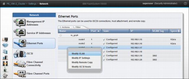
Figure 9-23 Modifying VLAN settings
Select Enable and type in the VLAN-tag to be enabled, as shown Figure 9-24.
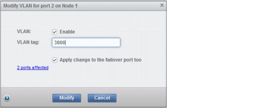
Figure 9-24 Enter VLAN tag
Two ports are affected. A port on one node corresponds to the same port on the partner node because nodes work in clusters.
Click the 2 ports affected link to view additional details, and then Modify, as shown in Figure 9-25.
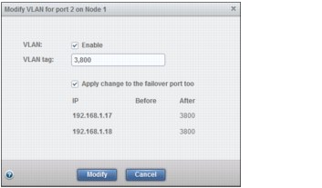
Figure 9-25 Enable VLAN tag 3800
The wizard requests confirmation that you are about to change VLAN tags for two ports. Click Yes, as shown in Figure 9-26.
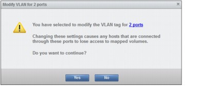
Figure 9-26 Confirm changes
The Modify Ethernet Port VLAN tag CLI commands run. Click Close to finish the configuration changes, as shown in Figure 9-27.
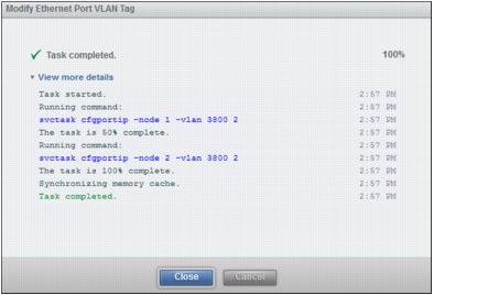
Figure 9-27 CLI commands run
The two ports now use modified VLAN-tags, which shows on the Ethernet Ports panel (Figure 9-28).
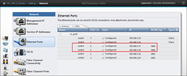
Figure 9-28 VLAN has been changed for two ports
For more information of configuring VLAN tagging, see the following Redbooks publication:
Implementing the IBM System Storage SAN Volume Controller V7.4, SG24-7933
9.3.4 iSCSI
Volumes can be mapped to a host to allow access for a specific server to a set of volumes. A host within the FlashSystem V9000 is a collection of host bus adapter (HBA) worldwide port names (WWPNs) or iSCSI qualified names (IQNs) that are defined on the specific server. The host IQN name can be obtained from the host iSCSI initiator software and in FlashSystem V9000 the host is configured to reflect this IQN name. For more information about how to configure a FlashSystem V9000 iSCSI host, see “Hosts in a FlashSystem V9000 configured with iSCSI interface cards” on page 323.
To change iSCSI node name and alias click Settings → Network → iSCSI. The iSCSI Configuration panel displays, as shown in Figure 9-29.
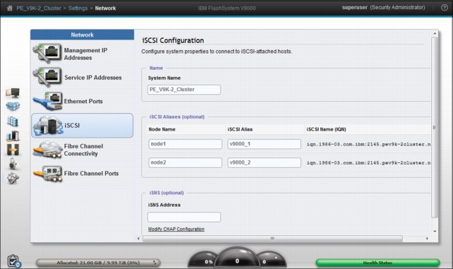
Figure 9-29 iSCSI configuration
|
Note: Changing a node name also changes the iSCSI-qualified name (IQN) of the node and might require reconfiguration of all iSCSI-attached hosts for the node.
|
iSCSI authentication
Authentication of the host server from the FlashSystem V9000 system is optional and disabled by default. The user can choose to enable the Challenge Handshake Authentication Protocol (CHAP) authentication, which involves sharing a CHAP secret between the FlashSystem V9000 system and the host. The FlashSystem V9000, as authenticator, sends a challenge message to the specific server (peer). The server responds with a value that is checked by the FlashSystem V9000. If there is a match, the FlashSystem V9000 acknowledges the authentication. If not, the FlashSystem V9000 ends the connection and does not allow any I/O to volumes.
A CHAP secret can be assigned to each FlashSystem V9000 host object. The host must then use CHAP authentication to begin a communications session with a node in the system. A CHAP secret can also be assigned to the system.
Volumes are mapped to hosts, and LUN masking is applied by using the same methods that are used for FC LUNs.
Because iSCSI can be used in networks where data security is a concern, the specification supports separate security methods. For more information about securing iSCSI, see Securing Block Storage Protocols over IP, RFC3723, which is available at this website:
9.3.5 Fibre Channel
Use the Fibre Channel Connectivity panel (Figure 9-30) to display the Fibre Channel connectivity between nodes, storage systems, and hosts. FlashSystem V9000 individual components are selected (1). Click Show Results (2) to populate the panel. You can save the report by clicking the Save icon (3).
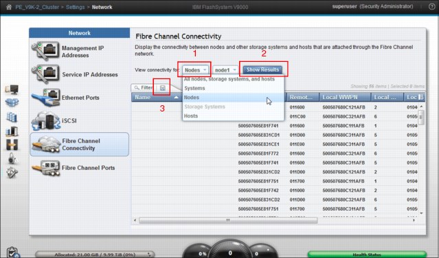
Figure 9-30 Fibre Channel Connectivity window
9.3.6 Fibre Channel ports
You can use the Fibre Channel Ports panel (Figure 9-31) in addition to SAN fabric zoning to restrict node-to-node communication. You can indicate specific ports to prevent communication between nodes in the local system or between nodes in a remote-copy partnership. This port specification is called Fibre Channel port mask.
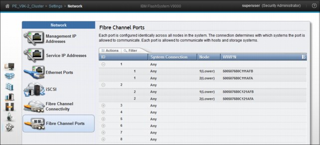
Figure 9-31 Fibre Channel Port types
9.4 Security menu
Select Security from the Settings menu (Figure 9-32) to manage the security of the system, including remote authentication and encryption.
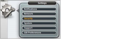
Figure 9-32 Select Security from the Settings Menu
Remote Authentication
When remote authentication is configured, users authenticate with their domain user and password rather than a locally created user ID and password. Remote authentication gives you central access control. If someone leaves the company, you only need to remove access at the domain controller, which means that no orphan user IDs remain on the storage system. As shown in the Remote Authentication panel (Figure 9-33), click Configure Remote Authentication (1) to see choices and to launch the wizard. Click Global Actions to refresh the LDAP cache (2).
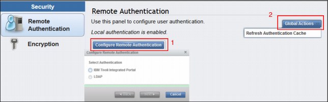
Figure 9-33 Remote Authentication panel
Encryption
IBM FlashSystem V9000 provides encryption, which protects against the potential exposure of sensitive user data and user metadata that are stored on discarded, lost, or stolen flash modules. Protection of encrypted data is enforced by encryption keys stored on external USB flash drives inserted in the controller component. A USB flash drive with a valid encryption key must be placed in one of the USB connectors of the FlashSystem V9000 controller nodes during power up, upgrades, restart, and many repair actions. Figure 9-34 shows the Encryption panel.
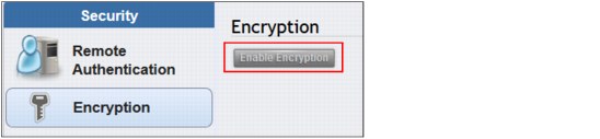
Figure 9-34 Enable Encryption
|
Note: The Enable Encryption button is disabled if either this system is already encrypted or encryption has not been enabled.
|
9.4.1 Configure remote authentication
When a FlashSystem V9000 system is created, the authentication settings default to local, which means that the IBM FlashSystem V9000 contains a local database of users and their privileges. Users can be created on the system and can log in using the user accounts they are given by the local superuser account.
You can create two types of users (local and remote) who can access the system. These types are based on how the users authenticate to the system.
Local users are authenticated through the authentication methods that are on the IBM FlashSystem V9000.
If the local user needs access to the management GUI, a password is needed for the user. If the user requires access to the command-line interface (CLI) through Secure Shell (SSH), either a password or a valid SSH key file is necessary. Local users must be part of a user group that is defined on the system.
A remote user is authenticated on a remote service with Lightweight Directory Access Protocol (LDAP) as configured in the Settings → Security section of the FlashSystem V9000 GUI (see “Remote Authentication” on page 361). Remote users have their roles defined by the remote authentication service.
Remote authentication is disabled by default and can be enabled to authenticate users against LDAP servers.
A user who needs access to the CLI must be configured as a local user on the IBM FlashSystem V9000.
Remote users do not need to be configured locally; they only need to be defined on the LDAP server.
User groups define roles that authorize the users within that group to a specific set of privileges on the system.
For users of the FlashSystem V9000 system, you can configure authentication and authorization using the CLI and the GUI as configured in the Users and User Groups menu.
For more information about configuring remote authentication and authorization for users of the IBM FlashSystem V9000, see these topics about remote authentication at the IBM FlashSystem V9000 web page in the IBM Knowledge Center:
•Managing security:
•Working with local and remote users:
Reasons for using remote authentication
Use remote authentication for the following reasons:
•Remote authentication saves you from having to configure a local user on every IBM storage system that exists in your storage infrastructure.
•If you have multiple LDAP enabled storage systems, remote authentication makes it more efficient to set up authentication.
•The audit log shows the domain user name of the issuer when commands are run. The domain user name is more informative than a local user name or just superuser.
•Remote authentication gives you central access control. If someone leaves the company, you only need to remove access at the domain controller, which means that there are no orphan user IDs left on the storage system.
Preparing the LDAP server
The first step in configuring LDAP is to prepare the LDAP server. We use a Microsoft Windows 2008 R2 Enterprise server, which we promoted to be a Domain Controller by using the dcpromo command. Next, we added the Active Directory Lightweight Directory Services computer role.
The privileges that the LDAP user gets on the IBM FlashSystem V9000 are controlled by user groups on the storage system. There must be matching user groups on the Active Directory (AD) server and on the IBM FlashSystem V9000, and the LDAP users must be added to the AD server group.
In our example (Figure 9-36), we create a group called FlashAdmin, which we use to manage our FlashSystem V9000 storage device.
To create this group, we need to log on to the AD Domain Controller and configure Active Directory. Complete the following steps:
1. An easy way to configure Active Directory from the AD controller is to go to Start → Run, type dsa.msc, and click OK. The Active Directory Users and Computers management console opens (Figure 9-35).
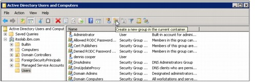
Figure 9-35 Active Directory Users and Computers window to create a new group
2. Click the Create a new group in the current container icon. The New Object - Group window opens (Figure 9-36).
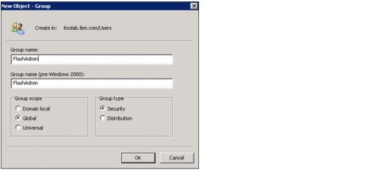
Figure 9-36 Active Directory to create a FlashAdmin group
3. Specify FlashAdmin for the new group name, keep the remaining default values, and click OK.
4. Highlight the users that you want to add to the FlashSystem V9000 storage administrator group and click the Adds the selected objects to a group you specify icon (Figure 9-37).
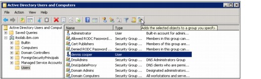
Figure 9-37 Adds the selected objects to a group you specify
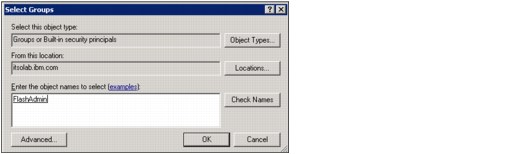
Figure 9-38 Active Directory Select Groups window to add users to the FlashAdmin group
Any other users that might be added to the FlashAdmin group get the same privileges on our FlashSystem V9000.
If other users with different privileges are required, another group on the IBM FlashSystem V9000 with different privileges is required. A group on the AD server with a matching name is also required.
Our LDAP server is now prepared for remote authentication.
Enabling remote authentication on FlashSystem V9000
The next step in configuring remote authentication for the IBM FlashSystem 900 is to specify the authentication server, test connectivity, and test whether users can authenticate to the LDAP server:
1. Select Settings → Security, and on the Security menu, click Remote Authentication. The default authentication method is Local authentication is enabled (Figure 9-39). Click Configure Remote Authentication.
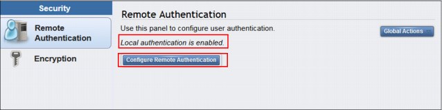
Figure 9-39 Configure Remote Authentication
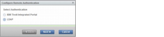
Figure 9-40 Remote Authentication wizard (step 1 of 4)
3. Select Microsoft Active Directory, and for Security, select None (Figure 9-41). Click Advanced Settings to expand it.
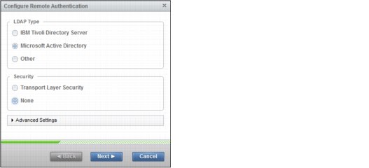
Figure 9-41 Remote Authentication wizard (step 2 of 4)
4. Any user with authority to query the LDAP directory can be used to authenticate. In our example, our Active Directory domain is itsolab.ibm.com, so we use the Administrator login name on the Domain itsolab.ibm.com to authenticate. Click Next (Figure 9-42).
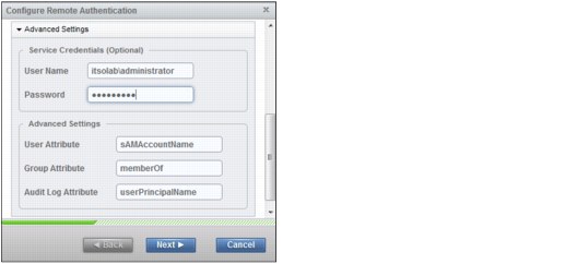
Figure 9-42 Remote Authentication wizard (step 3 of 4)
5. Type the IP address of the LDAP server and the LDAP Group Base Domain Name (DN) for Microsoft Active Directory.
You can obtain the LDAP User and Group Base DN for Microsoft Active Directory by using the following commands:
dsquery user -name <username>
dsquery group -name <group name>
To look up the Base DN, we log on to the LDAP server and run the following commands (Example 9-1).
Example 9-1 Checking the LDAP server for the Base DN
C:UsersAdministrator>dsquery group -name FlashAdmin
"CN=FlashAdmin,CN=Users,DC=itsolab,DC=ibm,DC=com"
C:UsersAdministrator>
The Base DN that we need to enable LDAP authentication requires only the domain part of the output in Example 9-1.
6. In the Base DN (Optional) field in the Configure Remote Authentication window (Figure 9-43), we type the following text:
DC=itsolab,DC=ibm,DC=com
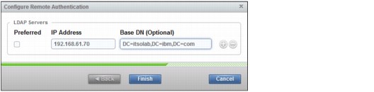
Figure 9-43 Remote Authentication wizard (step 4 of 4)
7. Click Finish to return to the Settings > Security window.
Figure 9-44 shows that LDAP is enabled and the window shows the preferences of the configured LDAP server.
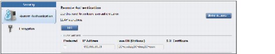
Figure 9-44 Remote Authentication is enabled
Creating the FlashSystem V9000 LDAP-enabled user group
The first part of our LDAP configuration is complete. However, we need to create a new user group on our FlashSystem 9000 with a name that matches the name that we configured on the LDAP server. We configured the name FlashAdmin on the LDAP server.
Complete the following steps:
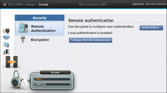
Figure 9-45 Select Users
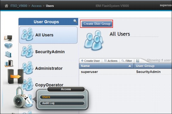
Figure 9-46 Create a new user group
3. The Create User Group window opens (Figure 9-47). For the Group Name, enter FlashAdmin, select Security Administrator, and select the Enable for this group check box under LDAP.
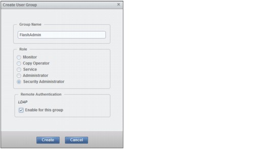
Figure 9-47 Select Security Administrator
|
Note: If the Remote Authentication field is not visible in the Create User Group window, remote authentication is disabled in Settings → Security.
|
Our new user group is created and enabled for remote authentication (Figure 9-48).
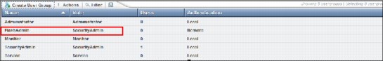
Figure 9-48 Remote user is created
Testing LDAP authentication
At this point, you can log out the superuser and log in with the LDAP user. However, before you do that, the Remote Authentication window provides a capability to test LDAP.
Complete the following steps:
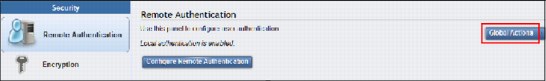
Figure 9-49 Test LDAP Connections
The Test LDAP Connections task window opens (Figure 9-50) and displays the CLI command that tests the connection. In a successful connection to the LDAP server, the Task completed message is displayed.
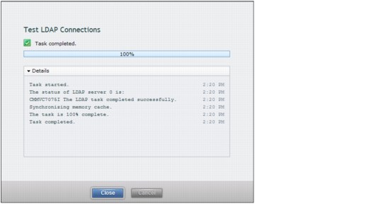
Figure 9-50 Remote Authentication: Test LDAP connections CLI result
2. From the Global Actions menu, you can also test whether the authentication for a specific user is functional. Click Test LDAP Authentication.
3. The next window opens (Figure 9-51). Type the user credentials of the LDAP user for whom you want to test authentication and click Test.
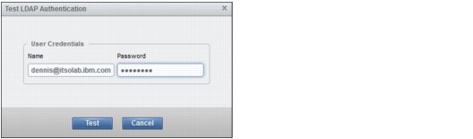
Figure 9-51 Remote Authentication: Test LDAP Authentication
When you click Test, the CLI command window opens (Figure 9-52):
– If the authentication is successful, you see the same output as in Figure 9-50 on page 369.
– If the test is unsuccessful, you see the message in Figure 9-52.
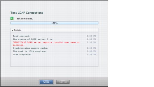
Figure 9-52 Remote Authentication: Test unsuccessful
Logging in as an LDAP user
Assuming that remote authentication is successful, the superuser user can now log out and the LDAP user can log in (Figure 9-53).
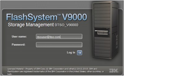
Figure 9-53 Login window for the LDAP user
Configuring remote authentication is complete.
9.4.2 Encryption
IBM FlashSystem V9000 provides optional encryption of data at rest, which protects against the potential exposure of sensitive user data and user metadata that are stored on discarded, lost, or stolen flash modules. Encryption of system data and system metadata is not required, so system data and metadata are not encrypted.
AES-XTS 256-bit data-at-rest encryption with local key management
Two functions are added to the encryption feature:
•Hot Encryption Activation: Adding an encryption license to a previously initialized system
•Encryption Rekey: Changing the encryption key on a previously initialized system
If you want to use encryption, ensure that you purchase Feature Code (FC) AF14: Encryption Enablement Pack (Plant).
Data Encryption Methology
The IBM FlashSystem V9000 data encryption uses the Advanced Encryption Standard (AES) algorithm, with a 256-bit symmetric encryption key in XTS mode. This encryption mode is known as XTS–AES–256, which is described in the IEEE 1619–2007 data encryption standard. The data encryption key itself is protected by a 256-bit AES key wrap when it is stored in non-volatile form. There are two layers of encryption used with stored data, first on the data being protected, and second on the data encryption key itself.
Protection Enablement Process (PEP)
The Protection Enablement Process (PEP) transforms a system from a state that is not protection-enabled to a state that is protection-enabled.
The PEP establishes a secret encryption access key to access the system, which must be stored and made available for use later, whenever the system needs to be unlocked. The secret encryption access key must be stored outside the system on a USB drive, which the system reads to obtain the key. The encryption access key must also be backed up to other forms of storage.
With FlashSystem V9000 two functions comprise the encryption capability:
•Hot Encryption Activation
Allows an unencrypted FlashSystem to be encryption-enabled while the system is running, without affecting customer data.
•Nondisruptive Rekey
Permits creating a new encryption access key that supersedes the existing key on a running FlashSystem without affecting customer data.
Encryption can be enabled in three ways:
•Activating encryption using the GUI
•Activating encryption using the CLI
•Creating new encryption keys (Rekey)
Consider these aspects of handling encryption and encryption keys:
•Keeping encryption keys from more systems on the same USB flash drives (stacking)
•Making copies of encryption keys
•Storing copies of USB flash drives holding encryption keys
•Leaving encryption keys in or out of the system during normal operation
FlashSystem V9000 can enable Encryption either during initialization using the setup wizard or after the system is initialized. When the encryption Feature Code AF14 is purchased IBM sends a total of three USB flash drives.
When V9000 encryption is activated, an encryption key is generated by the system to be used for access to encrypted data that is stored on the system. The GUI starts a wizard that guides you through the process of copying the encryption key to multiple USB flash drives. The following actions are considered preferred practices for copying and storing encryption keys:
1. Make copies of the encryption key on at least three USB flash drives to access the system.
2. In addition, copy the encryption keys to other forms of storage to provide resiliency and to mitigate risk, if, for example, the three USB flash drives are from a faulty batch of drives.
3. Test each copy of the encryption key to ensure that the key is recognized before writing any user data to the initialized system.
4. Securely store all copies of the encryption key. As an example, any USB flash drives that are not left inserted into the system can be locked in a safe. Take comparable precautions to securely protect any other copies of the encryption key stored to other forms of storage.
9.4.3 Enable the encryption license using V9000 GUI without Volumes
To install the encryption license on a previously initialized system, complete these steps:

Figure 9-54 Navigate to Licensed functions
2. In the Licensed Functions panel (Figure 9-55), select the License check box to activate the encryption license, and click Apply Changes.
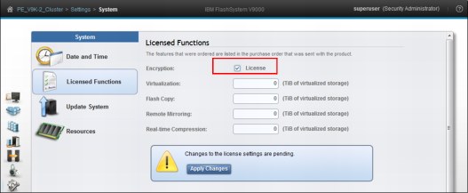
Figure 9-55 Activate the encryption license
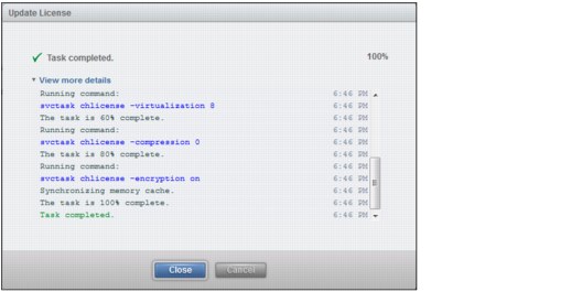
Figure 9-56 License Updated
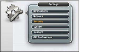
Figure 9-57 Open the Security panel
5. On the Settings > Security page, click Encryption, and then click Enable Encryption (Figure 9-58).
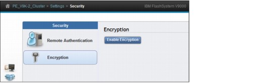
Figure 9-58 Enable Encryption
6. The enable Encryption wizard is activated (Figure 9-59). Locate three USB flash drives and click Next.
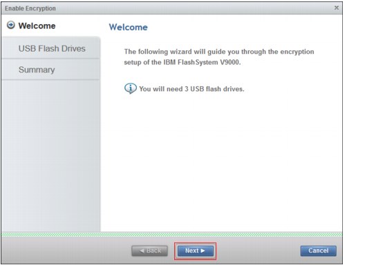
Figure 9-59 Encryption setup of FlashSystem V9000
7. Insert the IBM USB keys into the system (Figure 9-60), using two keys in one node and one key in the other. The extra key will be removed later.
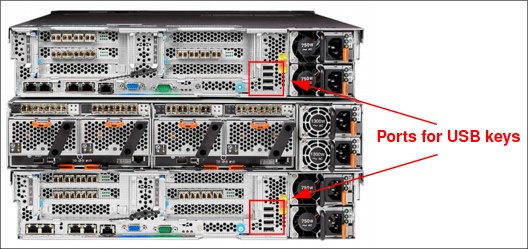
Figure 9-60 Set the IBM USB keys in the system
8. As shown in Figure 9-61, the USB key count is incremented (1) as each key is inserted. When the keys are created, click Next (2).
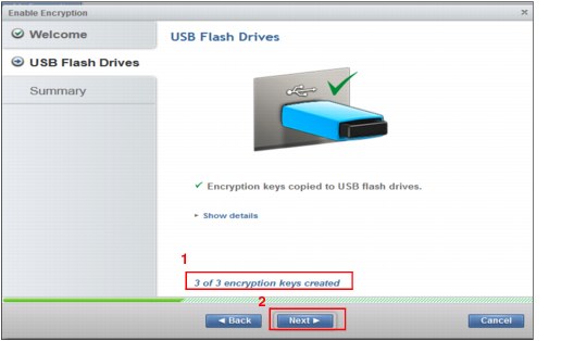
Figure 9-61 Create the encryption keys
|
Tip: Remove one of the USB keys and store it in a safe place. If security policies allow, leave the two remaining keys in the controller so they are available if the storage enclosure restarts. Canisters do restart during upgrades.
Remember if the encryption keys are not present, a storage enclosure reboot is not possible.
|
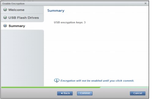
Figure 9-62 Commit to make the encryption effective
10. A confirmation window opens (Figure 9-63). The AE2 storage enclosure is now encrypted. Click Close.
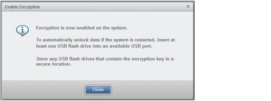
Figure 9-63 System is now encrypted
11. Review the Encryption panel to see that the system is encrypted (Figure 9-64).
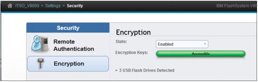
Figure 9-64 System is now Encrypted
12. If an event for the Encryption License occurs, such as the one shown in Figure 9-65, open the event panel and correct the event.
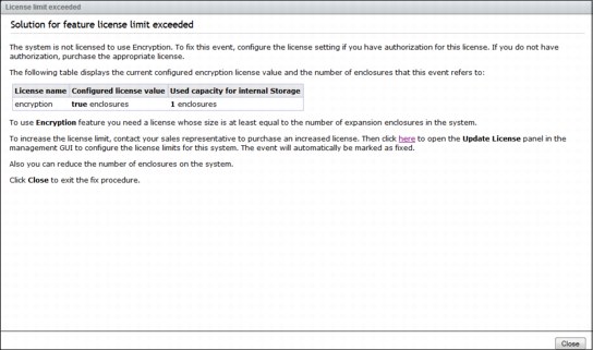
Figure 9-65 Example of an Encryption license event
13. To activate encryption on a previously initialized system, work with a support representative to complete the following steps:
a. Select Settings → System → Licensed Functions in the management GUI to enable the license (Figure 9-55 on page 373).
b. Select Settings → Security → Encryption in the management GUI, and click Enable Encryption (Figure 9-58 on page 374).
c. When the confirmation window opens in the Encryption panel, select Yes to indicate that you purchased the license and want to activate encryption.
In the wizard, you are prompted to insert the required number of USB flash drives into the system. When the system detects the USB flash drives, encryption keys automatically are copied on the USB flash drives. Ensure that you create any extra copies for backups. You can leave the USB flash drives inserted into the system. However, the area where the system is located must be secure to prevent keys being lost or stolen. If the area where the system is located is not secure, remove all the USB flash drives from the system and store securely.
Create several backup copies of the keys on either USB flash drives or another external storage media and store securely, if you have not done so.
Working with an encrypted FlashSystem V9000
At FlashSystem V9000 storage enclosure startup (power on) or to access data on an encrypted system, the encryption key must be provided by an outside source so the key is available. The encryption key is read from the USB flash drives on the V9000 controller created during system initialization. If you want the system to reboot automatically, a USB flash drive with the encryption keys must be left inserted in each controller node. Each V9000 storage enclosure must have these keys available in a controller so that both canisters have access to the encryption key when the enclosure powers on.
This method requires that the physical environment (where the system is located) be secure to ensure that an unauthorized person cannot make copies of encryption keys on the USB flash drives in order to gain access to data stored on the system.
|
Securing the USB keys: The standard practice is to implement secure operations by locking the USB keys in a secured location and not having them inserted into the controllers on the system. The storage enclosure remains offline until the USB key is manually inserted in one of the controllers.
|
To access encrypted data, FlashSystem V9000 encryption keys are required and are used only from the USB flash drive copies. Additional online copies can be made on other forms of storage; the keys are read from USB drives only when the storage controller canister restarts. The encryption key cannot be recovered or regenerated by IBM if all user-maintained copies are lost or unrecoverable.
|
Note: Encryption keys or data from FlashSystem V9000 cannot be recovered or regenerated by IBM on an encryption-enabled system if encryption keys are lost.
|
9.4.4 Handling encryption using CLI
The FlashSystem V9000 CLI can be used to enable encryption while the FlashSystem V9000 is running. This is a non-destructive procedure when handled correctly. An important step is to engage IBM support to ensure that the proper procedures are followed.
|
Note: Handling encryption using CLI involves numerous risks. To protect and preserve data, contact IBM Support for assistance with this procedure.
|
9.5 System menu
Select Settings → System (Figure 9-66). The System page opens where you can set the time and date for the cluster, perform software updates for the cluster, and set GUI preferences to manage licensed functions.
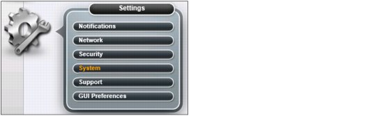
Figure 9-66 System selection
9.5.1 Date and Time option
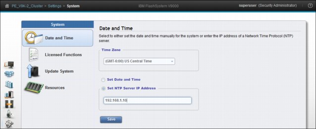
Figure 9-67 Date and Time panel
The preferred method for setting the date and time is to configure a Network Time Protocol (NTP) server. By using an NTP server, all log entries are stamped with an accurate date and time, which is important in troubleshooting. An example might be a temporarily broken FC link that caused a path failover at a connected host. To investigate the root cause of this event, you need to compare logs from the host, logs from the storage area network (SAN) switches, and logs from the IBM FlashSystem 900. If the date and time are not accurate, events cannot be easily compared and matched, which makes a root cause analysis much more difficult.
9.5.2 Licensed functions
The base license that is provided with your system includes the use of its basic functions. However, the extra licenses, listed in this section, can be purchased to expand the capabilities of your system. Administrators are responsible for purchasing extra licenses and configuring the systems within the license agreement, which includes configuring the settings of each licensed function on the system.
The base 5639-RB7 license entitles FlashSystem V9000 (machine type 9846/9848) to all the licensed functions, such as Virtualization, FlashCopy, Global and Metro Mirroring, and Real-time Compression. Any connected storage that is not a FlashSystem V9000 requires the External Virtualization license that is a per terabyte (or tebibyte, which is TiB) capacity unit of metric. TiB measures volume sizes in binary, so 1 GiB equals 1,073,741,824 bytes, which is 1024 to the power of three; where TB measures volume sizes in decimal, so 1 GB equals 1,000,000,000 bytes, which is 1000 to the power of three.
You use the Licensed Functions window in the System Setup wizard to enter External Virtualization licenses purchased for your system.
The system supports the following licensed functions for internal storage:
•Encryption
The system provides optional encryption of data at rest, which protects against the potential exposure of sensitive user data and user metadata that is stored on discarded, lost, or stolen storage devices. Encryption is licensed on a storage enclosure basis.
•External storage virtualization
The system does not require a license for its own control and expansion enclosures; however, a capacity-based license is required for any external systems that are being virtualized.
•FlashCopy
The FlashCopy function copies the contents of a source volume to a target volume. This license is capacity-based.
•Remote Copy (Global and Metro Mirror)
The remote-copy function enables the use of Metro Mirror and Global Mirror functions. This function enables you to set up a relationship between volumes on two systems, so that updates that are made by an application to one volume are mirrored on the other volume. The volumes can be in the same system or on two different systems. This license is capacity-based.
•Real-time Compression
With the compression function, data is compressed as it is written to the drive, saving additional capacity for the system. This license is capacity-based.
For more details about the base licensed features for FlashSystem V9000 internal storage, and for optional licensed features offered with FlashSystem V9000 for external storage, see section 2.5.2, “Software and licensing” on page 68.
Also see IBM FlashSystem V9000 Product Guide, TIPS1281 on the following website:
Figure 9-68 highlights two areas:
1. Changing the Flash Copy license from 0 TiB to 6 TiB (1).
2. The Apply Changes box (2) is automatically incremented.
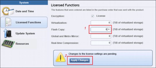
Figure 9-68 Licensed Functions pane
9.5.3 Update software
Concurrent upgrade is the default way to upgrade the FlashSystem V9000 system. All components of the system are upgraded including the AC2 controllers and AE2 storage enclosures. Performance is affected during heavy I/O load. We suggest that you plan a three-hour change window for your upgrades. This time can vary depending on your system configuration.
The V9000 system must be in a pristine state for upgrade to be allowed to start. Failures need to be resolved before starting upgrade.
We demonstrate how to update firmware through the GUI of the FlashSystem V9000. Before you start a system update, ensure that the system has no errors that might interfere with a successful update. Be sure that the errors are corrected.
|
Tip: Firmware release notes often contain the latest information about specifics of an upgrade. There is also an upgrade test utility that examines the system that can be run non-disruptively in advance of an upgrade. For more details about the upgrade test utility see 13.3.6, “Using the V9000 Software Upgrade Test Utility” on page 535.
The current firmware for the system can be downloaded from the Internet (if the system has access), or it can be downloaded by the administrator from the following web page:
|
The high-level view of the concurrent upgrade is shown in Figure 9-69.
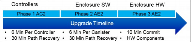
Figure 9-69 Upgrade overview
A single building block takes approximately 2.5 hours for code upgrade. Add 15 minutes for each extra AC2 controller; extra enclosures do not matter.
Host path recovery is an important part of the V9000 upgrade process. There are intentional waits to ensure that paths have recovered before upgrade proceeds to the next component. The remaining figures in this section show various stages of the upgrade.
Firmware update is initiated from the Update System page (Figure 9-70).
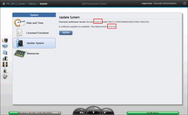
Figure 9-70 Update System panel
On this page, notice our current software level:
•Current version is 7.4.1.1
•Update version 7.5.1.0 is available
Before starting the firmware update, download the new firmware image file and the update test utility. The current firmware for the system can be downloaded from the Internet (if the system has access), or it can be downloaded by the administrator from the following address:
A firmware download requires an appropriate maintenance agreement or that the system is covered under warranty. When downloading firmware from IBM, the client must validate coverage by entering the system model number and serial number. The system model number and serial number are on the printed serial number label on the system.
|
Note: A firmware download from IBM is possible only if the system has an appropriate maintenance agreement or if the machine is under warranty.
|
You can update the FlashSystem V9000 firmware through the Settings menu. This update is referred to as Concurrent Code Load (CCL). Each controller and storage enclosure in the system automatically updates in sequence while maintaining interrupted accessibility for connected hosts.
The upgrade is concurrent. The process runs the upgrade utility and immediately starts the update if no problems are found. The test upgrade utility and code upgrade are started simultaneously, but run serially, with the test upgrade utility run first.
|
Note: The test utility cannot be run independently from the GUI.
|
To initiate CCL, select Settings → System → Update System. On the Update System panel, click Update (Figure 9-71).
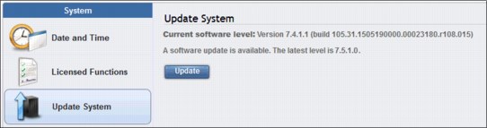
Figure 9-71 Update System panel
The Update System wizard begins (Figure 9-72) by requesting you to select the test utility and the update package. When you click Update, both files are uploaded and the running of the test utility begins. If the test utility does not find any issues, the upgrade begins.
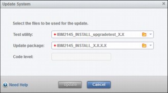
Figure 9-72 Test utility and firmware selection
Click the folder icon to locate the correct test utility and update package. The procedure for selecting the test utility file is shown in Figure 9-73.
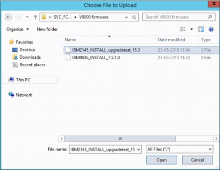
Figure 9-73 Upgrade test utility file selection
The purpose of running the test utility is to verify that no errors exist and that the system is ready to update. If any issue is discovered by the test utility, the firmware update stops and issues a message to the administrator about which problems to fix before the update system procedure can be repeated.
|
Tip: The upgrade test utility can be run multiple times by using the CLI. Details care in “Using the V9000 Software Upgrade Test Utility from the command line” on page 536.
|
The procedure for selecting the update package is shown in Figure 9-74.
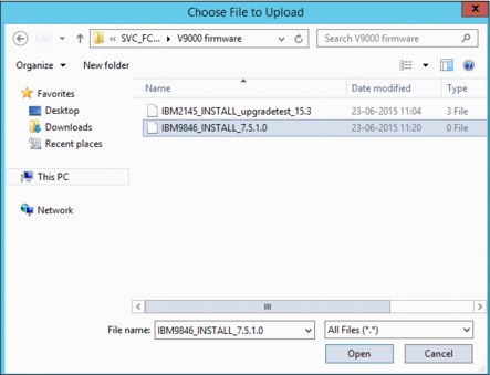
Figure 9-74 Update package file selection
Figure 9-75 shows that we selected the appropriate files for test utility and update package and we selected the target code level.
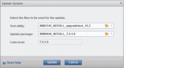
Figure 9-75 Test utility and firmware selection
The system inserts the current code level automatically, or the administrator can specify a different firmware level. In our example, we are updating to 7.5.1.0. Click Update to proceed.
The Update System panel opens where you can select Automatic update or Service Assistant Manual update. We select Automatic update and click Finish as shown in (Figure 9-76).
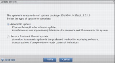
Figure 9-76 Update System panel
The update test utility and update package files are uploaded to the FlashSystem V9000 controller nodes, and then the firmware update for the entire system proceeds automatically.
The initial part of the Update System procedure is shown in Figure 9-77.
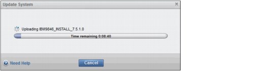
Figure 9-77 Code uploading panel
If any errors are identified by the test utility, they are indicated in the Update System panel. Any hardware error prevents the system update from proceeding. If an error is identified, take the correct actions to resolve the error identified by the update test utility.
|
Tip: During the upgrade, the GUI might go offline temporarily as the V9000 Controllers are restarted during the upgrade. Refresh your browser to reconnect.
|
The Concurrent Code Load (CCL) firmware update is now running in the background. While the system updates, the progress is shown in the progress indicators (Figure 9-78). In this figure, the health status bar in Figure 9-78 is showing red while the node is offline for update.
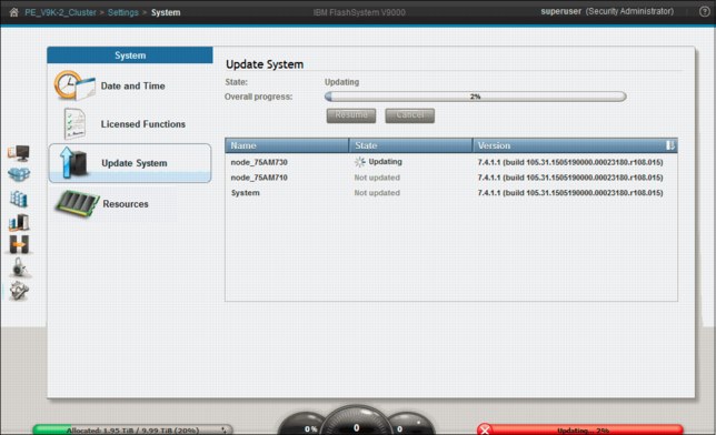
Figure 9-78 Updating system controller
The system can be operated normally while it is upgrading; however, no changes can be made until the firmware update completes. If you are trying to fix an error condition, you see the message shown in Figure 9-79 (Fixes cannot be applied while the system is being upgraded).

Figure 9-79 Fixes cannot be applied while upgrading
During the update, various messages display in the Update System window (Figure 9-80). The first controller completes its update and the second controller starts to update.
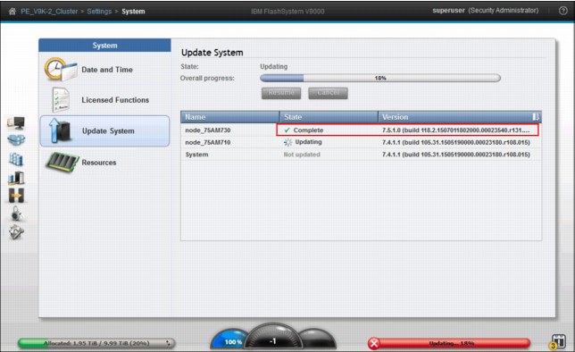
Figure 9-80 Update System panel, one node completed
|
Tip: Host path recovery is often quicker than the time the V9000 pauses; the system takes a conservative approach to ensure that paths are stabilized before proceeding.
|
After completing the update to the second V9000 controller, node the upgrade process moves to the storage enclosure. When the Update System wizard completes, the system returns to a healthy status. The system now has the current firmware (Figure 9-81).
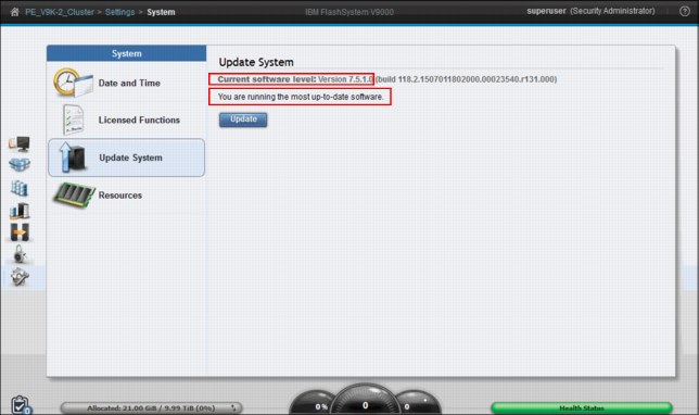
Figure 9-81 Firmware update is now complete
During the hardware update, all individual components in the system are being firmware-updated. For example, the I/O ports are updated, during which time they are being taken offline for update one-by-one.
|
Tip: Customer change windows for update should include the entire upgrade process.
|
As an alternative to upgrading firmware through the GUI, you can use the FlashSystem V9000 CLI. The process is described in the IBM Knowledge Center:
Search for the “Updating the software automatically using the CLI” topic.
9.5.4 Resources
Copy Services features and RAID require that small amounts of volume cache be converted from cache memory into bitmap memory to enable the functions to operate. If you do not have enough bitmap space allocated when you try to use one of the functions, you cannot complete the configuration. As an example, if bitmap space is too low, trying to expand a mirrored volume fails until the allocated bitmap space has been expanded.
Table 9-1 describes the amount of bitmap space necessary to configure the various copy services functions and RAID.
Table 9-1 Examples of memory required
|
Feature
|
Grain size
|
1 MB of memory provides the following volume capacity for the specified I/O group
|
|
Metro Mirror or Global Mirror
|
256 KB
|
2 TB of total Metro Mirror or Global Mirror volume capacity
|
|
FlashCopy
|
256 KB
|
2 TB of total FlashCopy source volume capacity
|
|
FlashCopy
|
64 KB
|
512 GB of total FlashCopy source volume capacity
|
|
Incremental FlashCopy
|
256 KB
|
1 TB of total incremental FlashCopy source volume capacity
|
|
Incremental FlashCopy
|
64 KB
|
256 GB of total incremental FlashCopy source volume capacity
|
|
Volume mirroring
|
256 KB
|
2 TB of mirrored volume capacity
|
In Figure 9-82 we change the memory limit for Volume Mirroring from the default of 20 MiB to 40 MiB. Type in the new amount of bitmap space and click Save.
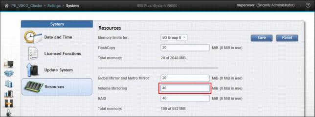
Figure 9-82 Change bitmap space for Volume Mirroring
|
Remember: If you do not have enough bitmap space allocated when you try to use one of the functions, you cannot complete the configuration.
|
9.6 Support menu
You can download support packages that contain log files and information that can be sent to support personnel to help troubleshoot the system. You can either download individual log files or download statesaves, which are dumps or live dumps of system data.
9.6.1 Download support package
Click Settings → Support when log files are requested by IBM Support. IBM Support often requests log files when responding to an automatic support case is opened by the call home function or a support case is opened by the FlashSystem V9000 administrators.
|
Tip: Log files are needed in most of the support cases processed for the V9000. Clients who upload these logs when the support ticket number is available often have issues resolved quicker than waiting for IBM support to ask for them.
|
The system administrator downloads the requested support package from the system and then uploads it to IBM Support. IBM Support then analyzes the data.
To download a support package, follow these steps, as shown in Figure 9-83:
1. Select Settings → Support and click Download Support Package.
2. Select the type of support package to download (we selected Standard logs), and then click Download.
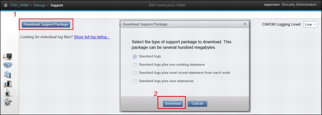
Figure 9-83 Download support package panel
You can download the following types of support packages:
•Standard logs: Contains the most recent logs that were collected for the system. These logs are most commonly used by support to diagnose and solve problems.
•Standard logs plus one existing statesave: Contains the standard logs for the system and an existing statesave from any of the nodes in the system. Statesaves are also known as dumps or livedumps.
•Standard logs plus the most recent statesave from each node: Contains the standard logs for the system and the most recent statesave from each of the nodes on the system.
•Standard logs plus new statesave: Generates a new statesave (live dump) for all of the nodes in the system and packages them with the most recent logs.
IBM Support usually requests that you click Standard logs to begin an investigation. The length of time to download these logs from the IBM FlashSystem V9000 can be in the range of minutes to an hour, depending on the situation and the size of the support package that is downloaded. The download is initiated by clicking Download (Figure 9-83 on page 392).
Figure 9-84 shows that you can monitor the details of the running command. When this completes, it is replaced with the save-file form.
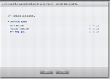
Figure 9-84 Generating the support package
The destination of the support package file is the system where the web browser was launched. Figure 9-85 shows the next step of saving the support package file on our system.
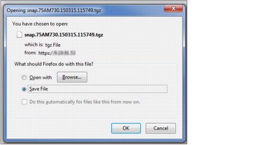
Figure 9-85 Saving the Snap File
IBM Support usually requests log files to be uploaded to a specific problem management record (PMR) number, using Enhanced Customer Data Repository (EcuRep) as the upload method to IBM. EcuRep is at the following address:
9.6.2 Download individual log files
You can select individual logs to download to review or send them directly to IBM Support. You can also increase CIMOM1 logging levels to add details to the support packages on the CIMOM-related events. However, increasing the logging level can affect system performance and is best used temporarily when you are resolving issues on the system.
After analyzing the uploaded support package, IBM Support might request additional files. To locate these files, select Settings → Support and click Show full log listing. This option supports the download of specific and individual log files.
An example is shown in Figure 9-86:
1. Select a single error log file.
2. Click Actions → Download.
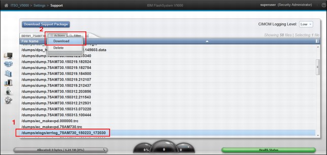
Figure 9-86 Download specific file dialog
|
Note: Log files are saved from each of the components of the system.
|
9.6.3 Deleting log files
You can also delete certain types of log files from the system. To preserve the configuration and trace files, any files that match the following wildcard patterns cannot be deleted:
•*svc.config*
•.trc
•.trc.old
|
The Delete option: When the Delete option is not available, the file cannot be deleted because it is being used by the system.
|
Figure 9-87 shows the deletion process:
1. Select an old snap file.
2. Click Actions → Delete.
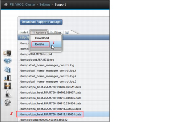
Figure 9-87 Deleting individual files
|
Tip: Systems running in production for a long time might require that old files be cleaned up before upgrades. Snaps with statesaves are large files, for example.
|
9.6.4 GUI Preferences
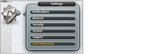
Figure 9-88 GUI Preferences selection
This GUI Preferences panel opens (Figure 9-89). Use this panel manipulate behaviors in the GUI. The panel has four sections:
1. Refresh GUI Objects
2. Knowledge Center
3. Extent Sizes
4. Accessibility
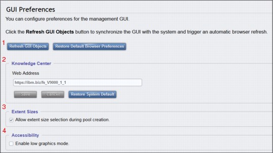
Figure 9-89 GUI Preferences panel
Refresh GUI Objects or Restore Default Browser Preferences
Click either of the following buttons:
•Refresh GUI Objects
Causes all the panels in the GUI to be refreshed. FlashSystem V9000 management interface keeps the majority of windows up-to-date in real time. This operation provides you with a mechanism to initiate a refresh of all the panels.
•Restore Default Browser Preferences
Causes any settings that are changed in the browser to revert to their default settings.
Knowledge Center
You can customize the online documentation that IBM provides, referred to as the IBM Knowledge Center. IBM offers customers opportunities to participate in beta test programs. This option can be used to change the web address to point to alternate documentation.
Extent Sizes
Consistent extent sizes are an important factor when migrating VDisks between pools on the V9000. Clearing Allow extent size selection during pool creation means that the user is not offered the option to change the extent size from the default presented by the system.
Accessibility
By selecting Enable low graphics mode, the user can customize the GUI to use less bandwidth. This option is available primarily for slow Internet connections; most clients do not need to change this parameter.
1 Common Information Model Object Manager (CIMOM)
..................Content has been hidden....................
You can't read the all page of ebook, please click here login for view all page.