


Guidelines: Port utilization in an IBM FlashSystem V9000 scalable environment
To maximize the full potential of performance and low latency of IBM FlashSystem V9000 (FlashSystem V9000) with FlashCore technology in a scalable environment, several important items must be considered in configuring your environment. For example, host, internal and external storage, intra-cluster, and optional Remote Copy ports must be properly designated and zoned in order to optimize performance and properly isolate the types of Fibre Channel traffic.
This appendix compares and provides guidelines for two suggested methods of port utilization that can be implemented, depending on your requirements:
•FlashSystem V9000 port utilization for infrastructure savings
This method reduces the number of required customer Fibre Channel ports that are attached to the customer fabrics. This method provides high performance and low latency but performance might be port-limited for certain configurations. Intra-cluster communication and AE2 storage traffic occur over the internal switches.
•FlashSystem V9000 port utilization for performance
This method uses more customer switch ports to improve performance for certain configurations. Only ports that are designated for intra-cluster communication are attached to private internal switches. The private internal switches are optional and all ports can be attached to customer switches.
Following the cabling guidelines in this appendix, for the FlashSystem V9000 port utilization for performance method, can result in performance improvements up to 40% for sequential reads and up to 80% for sequential writes.
Random workloads can also see performance benefits with the performance method because more host ports are available when compared with the infrastructure savings method. This benefit is more pronounced for a FlashSystem V9000 solution that includes dedicated ports for remote copy.
A.1 Overview
FlashSystem V9000 provides a flexible architecture for assigning port resources. Two primary methods of port utilization in a Fibre Channel environment are suggested depending on your needs:
•FlashSystem V9000 port utilization for infrastructure savings
•FlashSystem V9000 port utilization for performance
Comparison of port utilization methods
The infrastructure savings method has dedicated internal switches for the FlashSystem V9000 AE2 storage enclosure connections and also intra-cluster communication with a reduced number of customer host facing ports.
The performance method uses the customer fabric for all connections (with the option to use dedicated internal switches for intra-cluster communication). The ports have designated purposes based on fabric attachment, zone assignments, and port masking. This method provides shared-use ports that use the full bidirectional capabilities of Fibre Channel.
The performance method has up to 80% improved sequential write performance and 40% improved sequential read performance when compared with the infrastructure savings method.
Either method can designate host ports for remote copy and mirroring. The performance method has the least effect on overall system performance when ports are designated to remote copy.
Either method supports attachment to external storage. In both cases, zones in the customer fabric are required for attaching external storage.
The infrastructure savings method requires up to four types of zones: open zoning, host zones, with optional remote copy zones, or external storage zones.
The method for performance requires up to four types of zones; host zones, storage zones (internal/external), intra-cluster zones, with optional remote copy zones.
The infrastructure savings method has specific port cabling suggestions for the AE2 storage enclosures and AC2 controller nodes that are calculated to support connections and nondisruptive scalability for up to eight AC2 controller nodes and eight AE2 storage enclosures (four building blocks plus four AE2 storage enclosures). For details, see A.3, “Guidelines: The infrastructure savings method” on page 564.
The performance method requires customer planning to ensure nondisruptive scalability. For details, see A.2, “Guidelines: The performance method” on page 559.
A.2 Guidelines: The performance method
The performance method for port utilization provides shared use of ports that uses the full bidirectional capabilities of Fibre Channel.
Figure A-1 lists the connections to the two AC2 control enclosures, including the cluster connections to the switches that are internal to the building block, and host and storage connections to switches that are external to the building block.
The building blocks connect to two SAN fabrics within the building block (BB), and two customer fabrics external to the building block.
If you are not doing remote copy (Metro Mirror or Global Mirror), the ports designated for remote copy can be used for host/storage. Depending on the remote copy bandwidth, you might also use only one port per node. Figure A-1 provides an example of port utilization that designates ports for intra-cluster traffic, ports for host/storage traffic, and dedicated ports for remote copy.
|
Note: The performance method requires customer planning to ensure nondisruptive scalability.
|

Figure A-1 Cabling and port connections in scalable environment with port utilization for performance
|
Note: When comparing the port utilization for infrastructure savings in Figure A-6 on page 564 with the port utilization for performance listing in Figure A-1 on page 559, you see that the customer fabric port connection mapping and usage is much higher in the port utilization for performance method. This method provides shared-use ports that take advantage of the full bidirectional capabilities in Fibre Channel, resulting in higher performance.
|
Port mask
Figure A-1 on page 559 also lists the port masks (localfcportmask and partnetfcportmask) to use with these port designations.
Figure A-2 shows an example from the FlashSystem V9000 GUI that displays Fibre Channel port masks (localfcportmask and partnetfcportmask). This information is displayed when you select Settings → Network → Fibre Channel Ports → Actions → Modify Connection → View details.
Deviations from the usage of the table shown in Figure A-1 on page 559 requires corresponding changes to the port masks. The port masks are used to limit intra-cluster and remote copy traffic to designated ports. Proper zoning is still required.
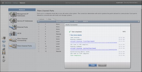
Figure A-2 Modify Fibre Channel port connection displays port mask
The following sections further detail the port assignment configurations for performance from Figure A-1 on page 559. We provide port assignment guidelines per FlashSystem V9000 control enclosures (AC2), and also the corresponding port assignments per FlashSystem V9000 storage enclosure (AE2) in a FlashSystem V9000 scalable environment for the following configurations for best performance and lowest latency:
Port assignments: 8 x 16 Gbps scalable building block
Figure A-3 depicts port assignments for an 8 x 16 Gbps scalable building block (BB) from the performance method (Figure A-1 on page 559). Port assignments are suggested for the scalable FlashSystem V9000 control enclosure (AC2) and corresponding FlashSystem V9000 storage enclosure (AE2), for optimal use of customer switch ports for improved performance.
|
Note: The zoning examples in A.4, “Guidelines: Zoning” on page 566 are all based on the 8 X 16 Gbps (Figure A-3). These zoning examples are similar for the 12 X 8 Gbps and the 8 X 8 Gbps + 4 X 16 Gbps scalable BB examples. The principles are the same for each of the following configurations, but do need to be modified based on the type and number of ports in each configuration.
|

Figure A-3 Performance method (port assignments: 8 x 16 Gbps scalable BB)
Port assignments: 12 x 8 Gbps scalable building block
Figure A-4 shows port assignments for a 12 x 8 Gbps scalable BB from the performance method (Figure A-1 on page 559). Port assignments are suggested for the scalable FlashSystem V9000 control enclosure (AC2) and corresponding FlashSystem V9000 storage enclosure (AE2) for optimal use of customer switch ports for improved performance.

Figure A-4 Performance method (port assignments: 12 x 8 Gbps scalable BB)
Port assignments: 8 x 8 Gbps + 4 x 16 Gbps scalable building block
Figure A-5 shows port assignments for an 8 x 8 Gbps + 4 X 16 Gbps scalable BB from the performance method (Figure A-1 on page 559).
Port assignments are suggested for the scalable FlashSystem V9000 control enclosure (AC2) and corresponding FlashSystem V9000 storage enclosure (AE2) for optimal use of customer switch ports for improved performance.
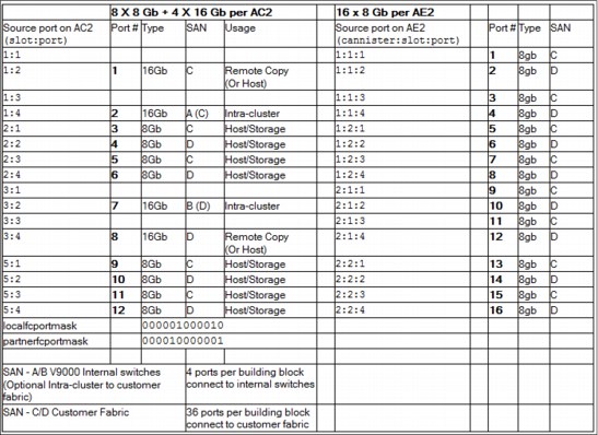
Figure A-5 Performance method (port assignments: 8 x 8 Gbps + 4 x 16 Gbps scalable BB)
A.3 Guidelines: The infrastructure savings method
The infrastructure savings method for port utilization provides a dedicated port setup. The ports are used either for host, storage, or intra-cluster communication. This method has dedicated internal switches for the FlashSystem V9000 AE2 storage enclosure connections and also intra-cluster communication with a reduced number of customer host facing ports.
Figure A-6 shows the connections to the two AC2 control enclosures, including the cluster connections to the switch that is internal to the building block. Host, remote copy, and external storage connections to switches that are external to the building block are shown.
The building blocks connect to two SAN fabrics within the building block (BB), and two customer fabrics external to the building block.

Figure A-6 Cabling and port connections in scalable environment for minimum infrastructure effect
The infrastructure savings method has specific port cabling guidelines for the AE2 storage enclosures and AC2 controller nodes. The guidelines are calculated to support connections and nondisruptive scalability for up to eight AC2 controllers nodes and eight AE2 storage enclosures (four building blocks plus four AE2 storage enclosures).
FlashSystem V9000 Scale-up and Scale-out Cabling and rules
The following diagram (Figure A-7) details the suggested scale-up and scale-out cabling for the first building block (BB1) for the infrastructure savings method using two 48-port Brocade switches and 16 Gbps ports for storage and intra-cluster communication.
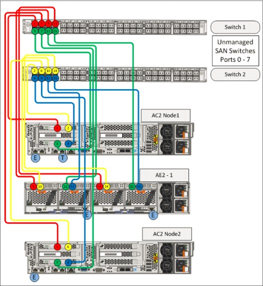
Figure A-7 FlashSystem V9000 BB1 Scale-up and Scale-out cabling - Infrastructure savings
The following cabling rules apply for this FlashSystem V9000 Scale-up and scale-out configuration:
•Slot 1 and 3: Intra-cluster and AE2 connectivity
– Port 1 from each 16 Gbps HBA goes to Switch 1
– Port 2 from each 16 Gbps HBA goes to Switch 2
•Slot 2 and 5: Host connectivity options
Four port 8 Gbps, 2 port 16 Gbps, 10 Gbps, FCoE
A.4 Guidelines: Zoning
This topic lists the zoning guidelines for FlashSystem V9000 port utilization for both the performance and infrastructure savings methods.
Port utilization method for performance
The method for performance requires up to four types of zones: host zones, storage zones (internal and external), intra-cluster zones, or with optional remote copy zones. They can be defined as follows:
•One cluster zone per fabric
•One host zone per fabric per node
•One storage zone per fabric per node
•One remote copy zone per fabric per node (if needed)
Figure A-8 shows an overview of the zoning that is configured for the performance method.

Figure A-8 FlashSystem V9000 scalable solution: Zoning for performance
Figure A-9 shows an example for zoning storage and host based on the tables for 8 x 16 Gbps building blocks. The same AC2 ports are used for both storage and host connections but in separate zones.
|
Tip: You do not want your local host ports to be in the same zone as the storage ports. The purpose of the two zones is to prevent hosts from accessing the FlashSystem V9000 managed storage directly.
|
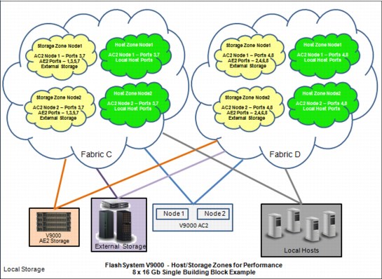
Figure A-9 FlashSystem V9000 scalable solution: Zoning storage and hosts for performance
Figure A-10 shows zoning remote copy and port connections for intra-cluster, based on the tables for 8 x 16 Gbps building blocks. Designated ports are used for both types of traffic.
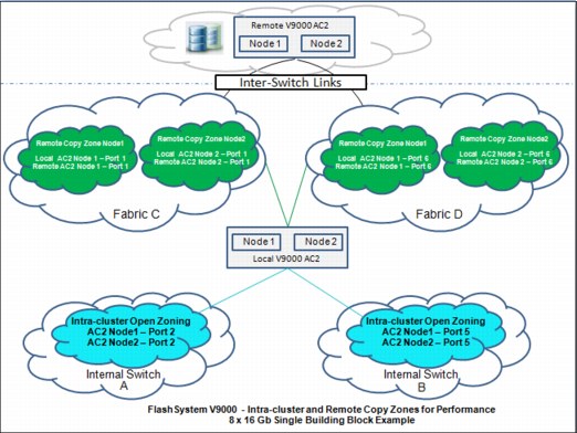
Figure A-10 FlashSystem V9000 scalable solution: Zoning remote copy and port connections for intra-clusters for performance
Port utilization method for infrastructure savings
The infrastructure savings method requires up to four types of zones:
•Open zoning
•Host zones
•Remote copy zones (optional)
•External storage zones
These zones are described as follows:
•Open zoning on internal switches
AC2 and AE2 components are connected as documented at the FlashSystem V9000 web page in the IBM Knowledge Center; see the “Installing” topic:
|
Note: These connections are done by a service provider.
|
•One host zone per fabric per node
•One external storage zone per fabric per node
•One Remote Copy zone per fabric per node (if needed)
Figure A-11 shows an overview of the zoning configured for the infrastructure savings method.
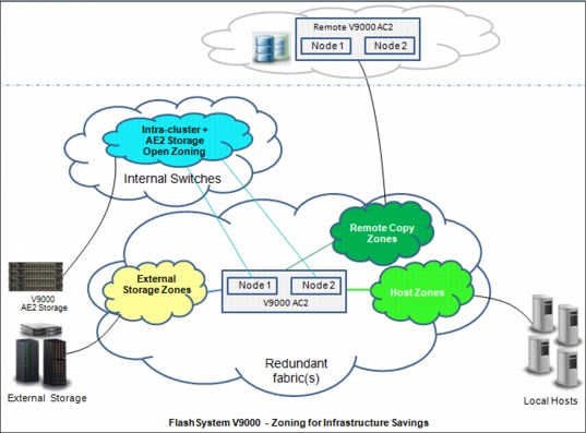
Figure A-11 FlashSystem V9000 scalable solution: Zoning for infrastructure savings
A.5 Summary
Guidelines are provided for two methods or port utilization in a scalable FlashSystem V9000 environment.Depending on customer requirements, the following methods of port utilization can be put into practice:
•FlashSystem V9000 port utilization for performance
This method uses more customer switch ports to improve performance for certain configurations. Only ports designated for intra-cluster communication are attached to private internal switches. The private internal switches are optional and all ports can be attached to customer switches.
•FlashSystem V9000 port utilization for infrastructure savings
This method reduces the number of required customer Fibre Channel ports that are attached to the customer fabrics. This method provides high performance and low latency but performance might be port-limited for certain configurations. Intra-cluster communication and AE2 storage traffic occur over the internal switches.
By following the port utilization cabling and zoning guidelines in this appendix, you can maximize the full potential of performance and low latency of IBM FlashSystem V9000 in enterprise-scalable environments.
A.6 Supported environments
FlashSystem V9000 can be used in different port utilizations. To check for supported switches, use the IBM System Storage Interoperation Center (SSIC):
Use the following values for your search:
•For “Storage Family,” select “IBM System Storage Enterprise Flash”
•For “Storage Version,” select “FlashSystem V9000 7.5.x”
•For “Connection Protocol,” select “Fibre Channel”
Validate that the intended FC switches are listed in the “SAN or Networking” list.
If there are additional host-side details, such as platform, OS, or multipathing, that restricts your switch selection. Choose the appropriate selections in the appropriate lists.
..................Content has been hidden....................
You can't read the all page of ebook, please click here login for view all page.