
Chapter 10
The Geometry Shader
The geometry shader stage is an optional stage that sits between the vertex and pixel shader stages. While the vertex shader inputs vertices, the geometry shader inputs entire primitives. For example, if we were drawing triangle lists, then the geometry shader program would be executed for each triangle T in the list:
for(UINT i = 0; i < numTriangles; ++i)
OutputPrimitiveList = GeometryShader( T[i].vertexList );
Notice the three vertices of each triangle are input into the geometry shader. The main advantage of the geometry shader is that it can create or destroy geometry. For example, the input primitive can be expanded into one or more other primitives, or the geometry shader can choose not to output a primitive based on some condition. Note that the output primitives need not be the same type as the input primitive; for instance, a common application of the geometry shader is to expand a point into a quad (two triangles).
The primitives output from the geometry shader are defined by a vertex list. Vertex positions leaving the geometry shader must be transformed to homogeneous clip space. After the geometry shader stage, we have a list of vertices defining primitives in homogeneous clip space. These vertices are projected (homogeneous divide), and then rasterization occurs as usual.
Objectives:
![]() To learn how to program geometry shaders.
To learn how to program geometry shaders.
![]() To understand how the billboard algorithm can be implemented efficiently using the geometry shader.
To understand how the billboard algorithm can be implemented efficiently using the geometry shader.
![]() To discover auto-generated primitive IDs and some of their applications.
To discover auto-generated primitive IDs and some of their applications.
![]() To learn how to create and use texture arrays, and understand why they are useful.
To learn how to create and use texture arrays, and understand why they are useful.
10.1 Programming Geometry Shaders
Programming geometry shaders is a lot like programming vertex or pixel shaders, but there are some differences. The following code shows the general form:
[maxvertexcount(N)]
void ShaderName (
PrimitiveType InputVertexType InputName [NumElements],
inout StreamOutputObject<OutputVertexType>OutputName)
{
// Geometry shader body…
}
We must first specify the maximum number of vertices the geometry shader will output for a single invocation. This is done by setting the max vertex count before the shader definition:
[maxvertexcount(N)]
where N is the maximum number of vertices the geometry shader will output for a single invocation. The number of vertices a geometry shader can output per invocation is variable, but it cannot exceed the defined maximum.
The geometry shader takes two parameters: an input parameter and an output parameter. (Actually, it can take more, but that is a special topic; see §10.2.4.) The input parameter is always an array of vertices — one vertex for a point, two for a line, three for a triangle, four for a line with adjacency, and six for a triangle with adjacency. The vertex type of the input vertices is the vertex type returned by the vertex shader (e.g., VS_OUT). The input parameter must be prefixed by a primitive type, describing the type of primitives being input into the geometry shader. This can be any one of the following:
![]() point: The input primitives are points.
point: The input primitives are points.
![]() line: The input primitives are lines (lists or strips).
line: The input primitives are lines (lists or strips).
![]() triangle: The input primitives are triangles (lists or strips).
triangle: The input primitives are triangles (lists or strips).
![]() lineadj: The input primitives are lines with adjacency (lists or strips).
lineadj: The input primitives are lines with adjacency (lists or strips).
![]() triangleadj: The input primitives are triangles with adjacency (lists or strips).
triangleadj: The input primitives are triangles with adjacency (lists or strips).
Note: The input primitive into a geometry shader is always a complete primitive (e.g., two vertices for a line, three vertices for a triangle). Thus the geometry shader does not need to distinguish between lists and strips. For example, if you are drawing triangle strips, the geometry shader is still executed for every triangle in the strip, and the three vertices of each triangle are passed into the geometry shader as input.
The output parameter always has the inout modifier. Additionally, the output parameter is always a stream type. A stream type stores a list of vertices that define the geometry the geometry shader is outputting. A geometry shader adds a vertex to the outgoing stream list using the intrinsic Append method:
void StreamOutputObject<OutputVertexType>::Append(OutputVertexType v);
A stream type is a template type, where the template argument is used to specify the vertex type of the outgoing vertices (e.g., GS_OUT). There are three possible stream types:
![]() PointStream<OutputVertexType>: A list of vertices defining a point list.
PointStream<OutputVertexType>: A list of vertices defining a point list.
![]() LineStream<OutputVertexType>: A list of vertices defining a line strip.
LineStream<OutputVertexType>: A list of vertices defining a line strip.
![]() TriangleStream<OutputVertexType>: A list of vertices defining a triangle strip.
TriangleStream<OutputVertexType>: A list of vertices defining a triangle strip.
The vertices output by a geometry shader form primitives; the type of output primitive is indicated by the stream type (PointStream, LineStream, TriangleStream). For lines and triangles, the output primitive is always a strip. Line and triangle lists, however, can be simulated by using the intrinsic RestartStrip method:
void StreamOutputObject<OutputVertexType>::RestartStrip();
For example, if you wanted to output triangle lists, then you would call RestartStrip each time three vertices were appended to the output stream.
Below are some specific examples of geometry shader signatures:
// EXAMPLE 1: GS outputs at most 4 vertices. The input primitive is
// a line. The output is a triangle strip.
//
[maxvertexcount(4)]
void GS(line VS_OUT gIn[2],
inout TriangleStream<GS_OUT> triStream)
{
// Geometry shader body…
}
//
// EXAMPLE 2: GS outputs at most 32 vertices. The input primitive is
// a triangle. The output is a triangle strip.
//
[maxvertexcount(32)]
void GS(triangle VS_OUT gIn[3],
inout TriangleStream<GS_OUT> triStream)
{
// Geometry shader body…
}
//
// EXAMPLE 3: GS outputs at most 4 vertices. The input primitive
// is a point. The output is a triangle strip.
//
[maxvertexcount(4)]
void GS(point VS_OUT gIn[1],
inout TriangleStream<GS_OUT> triStream)
{
// Geometry shader body…
}
The following geometry shader illustrates the Append and RestartStrip methods; it inputs a triangle, subdivides it (see Figure 10.1), and outputs the four subdivided triangles:
struct VS_OUT
{
float3 posL : POSITION;
float3 normalL : NORMAL;
float4 diffuse : DIFFUSE;
float4 spec : SPECULAR;
};
struct GS_OUT
{
float4 posH : SV_POSITION;
float3 posW : POSITION;
float3 normalW : NORMAL;
float4 diffuse : DIFFUSE;
float4 spec : SPECULAR;
};
[maxvertexcount(8)]
void GS(triangle VS_OUT gIn[3],
inout TriangleStream<GS_OUT> triStream)
{
GS_OUT gOut;
// Same materials for all vertices.
gOut.diffuse = gIn[0].diffuse;
gOut.spec = gIn[0].spec;
// Use face normal for vertex normals.
float3 e0 = gIn[1].posL - gIn[0].posL;
float3 e1 = gIn[2].posL - gIn[0].posL;
float3 n = normalize( cross(e0, e1) );
gOut.normalW = mul(float4(n, 0.0f), gWorld);
// Compute edge midpoints.
float3 m0 = 0.5f*(gIn[0].posL+gIn[1].posL);
float3 m1 = 0.5f*(gIn[1].posL+gIn[2].posL);
float3 m2 = 0.5f*(gIn[2].posL+gIn[0].posL);
// 1
// *
// /
// /
// m0*-----*m1
// / /
// / /
// *-----*-----*
// 0 m2 2
float3 v[6];
v[0] = gIn[0].posL;
v[1] = m0;
v[2] = m2;
v[3] = m1;
v[4] = gIn[2].posL;
v[5] = gIn[1].posL;
// We can draw the subdivision in two strips:
// Strip 1: bottom three triangles
// Strip 2: top triangle
for(int i = 0; i < 5; ++i)
{
gOut.posW = mul(float4(v[i], 1.0f), gWorld);
gOut.posH = mul(float4(v[i], 1.0f), gWVP);
triStream.Append(gOut);
}
triStream.RestartStrip();
gOut.posW = mul(float4(v[1], 1.0f), gWorld);
gOut.posH = mul(float4(v[1], 1.0f), gWVP);
triStream.Append(gOut);
gOut.posW = mul(float4(v[5], 1.0f), gWorld);
gOut.posH = mul(float4(v[5], 1.0f), gWVP);
triStream.Append(gOut);
gOut.posW = mul(float4(v[3], 1.0f), gWorld);
gOut.posH = mul(float4(v[3], 1.0f), gWVP);
triStream.Append(gOut);
}
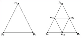
Figure 10.1: Subdividing a triangle into four equally sized triangles. Observe that the three new vertices are the midpoints along the edges of the original triangle.
Once a geometry shader has been implemented, we must bind it to an effect pass if it is to be used when rendering:
technique10 TreeBillboardTech
{
pass P0
{
SetVertexShader(CompileShader(vs_4_0, VS()));
SetGeometryShader(CompileShader(gs_4_0, GS()));
SetPixelShader(CompileShader(ps_4_0, PS()));
}
}
Note: Given an input primitive, the geometry shader can choose not to output it. In this way, geometry is “destroyed” by the geometry shader, which can be useful for some algorithms.
Note: If you do not output enough vertices to complete a primitive in a geometry shader, then the partial primitive is discarded.
10.2 Tree Billboards Demo
10.2.1 Overview
When trees are far away, a billboarding technique is used for efficiency. That is, instead of rendering the geometry for a fully 3D tree, a picture of a 3D tree is painted on the quad (see Figure 10.2). From a distance, you cannot tell that a billboard is being used. However, the trick is to make sure that the billboard always faces the camera (otherwise the illusion would break).
Assuming the y-axis is up and the xz-plane is the ground plane, the tree billboards will generally be aligned with the y-axis and just face the camera in the xz-plane. Figure 10.3 shows the local coordinate systems of several billboards from a bird’s-eye view — notice that the billboards are “looking” at the camera.

Figure 10.2: A tree billboard texture with alpha channel.

Figure 10.3: Billboards facing the camera.
So given the center position C = (Cx, Cy, Cz) of a billboard in world space and the position of the camera E = (Ex, Ey, Ez) in world space, we have enough information to describe the local coordinate system of the billboard relative to the world space:

And recall that the world matrix takes the form:

Note that the billboard matrix differs for each billboard, so it must be computed for each billboard.
For this demo, we will construct a list of point primitives (D3D10_PRIMITIVE_TOPOLOGY_POINTLIST) that lie slightly above a land mass. These points represent the centers of the billboards we want to draw. In the geometry shader, we will expand these points into billboard quads. In addition, we will compute the world matrix of the billboard in the geometry shader. Figure 10.4 shows a screenshot of the demo.

Figure 10.4: Screenshot of the Tree Billboards demo.
As Figure 10.4 shows, this sample builds off the Clip Pixel demo from Chapter 8. Most of the billboard-specific code occurs in the TreeSprites.h, TreeSprites.cpp, and tree.fx files.
Note: An inefficient implementation of billboards would draw the billboards one-by-one: For each billboard, the CPU would compute the world matrix, set the world matrix to the effect file, and then draw the billboard. With our approach, all the billboards can be drawn with a single draw call, and the GPU computes the world matrix instead of the CPU, thereby freeing the CPU to do other work.
10.2.2 Vertex Structure
We use the following vertex structure for our billboard points:
struct TreeVertex
{
D3DXVECTOR3 centerW;
D3DXVECTOR2 sizeW;
};
D3D10_INPUT_ELEMENT_DESC vertexDesc[] =
{
{"POSITION", 0, DXGI_FORMAT_R32G32B32_FLOAT, 0, 0,
D3D10_INPUT_PER_VERTEX_DATA, 0},
{"SIZE", 0, DXGI_FORMAT_R32G32_FLOAT, 0, 12,
D3D10_INPUT_PER_VERTEX_DATA, 0},
};
The vertex stores a point that represents the center position of the billboard in world space. It also includes a size member, which stores the width/height of the billboard (scaled to world space units); this is so the geometry shader knows how large the billboard should be after expansion (see Figure 10.5). By having the size vary per vertex, we can easily allow for billboards of different sizes.
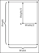
Figure 10.5: Expanding a point into a quad.
Excepting texture arrays (see §10.3), the other C++ code in the TreeSprites.h/.cpp files should be routine Direct3D code by now (creating vertex buffers, effects, invoking draw methods, etc.). Thus we will now turn our attention to the tree.fx file.
10.2.3 Effect File
Since this is our first demo with a geometry shader, we will show the entire effect file here so that you can see how it fits together with the vertex and pixel shaders and the other effect objects. This effect also introduces some new objects that we have not discussed yet (SV_PrimitiveID and Texture2DArray); these items will be discussed next. For now, mainly focus on the geometry shader program GS, which expands a point into a quad and aligns the quad to face the camera, as described in §10.2.1.
//=====================================================================
// tree.fx by Frank Luna (C) 2008 All Rights Reserved.
//
// Uses the geometry shader to expand points into y-axis
// aligned billboards.
//=====================================================================
#include "lighthelper.fx"
cbuffer cbPerFrame
{
Light gLight;
float3 gEyePosW;
float4x4 gViewProj;
};
// Nonnumeric values cannot be added to a cbuffer.
Texture2DArray gDiffuseMapArray;
SamplerState gTriLinearSam
{
Filter = MIN_MAG_MIP_LINEAR;
AddressU = Wrap;
AddressV = Wrap;
};
struct VS_IN
{
float3 centerW : POSITION;
float2 sizeW : SIZE;
};
struct VS_OUT
{
float3 centerW : POSITION;
float2 sizeW : SIZE;
};
struct GS_OUT
{
float4 posH : SV_POSITION;
float3 posW : POSITION;
float3 normalW : NORMAL;
float2 texC : TEXCOORD;
uint primID : SV_PrimitiveID;
};
VS_OUT VS(VS_IN vIn)
{
VS_OUT vOut;
// Just pass data into geometry shader stage.
vOut.centerW = vIn.centerW;
vOut.sizeW = vIn.sizeW;
return vOut;
}
[maxvertexcount(4)]
void GS(point VS_OUT gIn[1],
uint primID : SV_PrimitiveID,
inout TriangleStream<GS_OUT> triStream)
{
//
// Compute 4 triangle strip vertices (quad) in local space.
// The quad faces down the +z axis in local space.
//
float halfWidth = 0.5f*gIn[0].sizeW.x;
float halfHeight = 0.5f*gIn[0].sizeW.y;
float4 v[4];
v[0] = float4(-halfWidth, -halfHeight, 0.0f, 1.0f);
v[1] = float4(+halfWidth, -halfHeight, 0.0f, 1.0f);
v[2] = float4(-halfWidth, +halfHeight, 0.0f, 1.0f);
v[3] = float4(+halfWidth, +halfHeight, 0.0f, 1.0f);
//
// Compute texture coordinates to stretch texture over quad.
//
float2 texC[4];
texC[0] = float2(0.0f, 1.0f);
texC[1] = float2(1.0f, 1.0f);
texC[2] = float2(0.0f, 0.0f);
texC[3] = float2(1.0f, 0.0f);
//
// Compute world matrix so that billboard is aligned with
// the y-axis and faces the camera.
//
float3 up = float3(0.0f, 1.0f, 0.0f);
float3 look = gEyePosW - gIn[0].centerW;
look.y = 0.0f; // y-axis aligned, so project to xz-plane
look = normalize(look);
float3 right = cross(up, look);
float4x4 W;
W[0] = float4(right, 0.0f);
W[1] = float4(up, 0.0f);
W[2] = float4(look, 0.0f);
W[3] = float4(gIn[0].centerW, 1.0f);
float4x4 WVP = mul(W, gViewProj);
//
// Transform quad vertices to world space and output
// them as a triangle strip.
//
GS_OUT gOut;
[unroll]
for(int i = 0; i < 4; ++i)
{
gOut.posH = mul(v[i], WVP);
gOut.posW = mul(v[i], W);
gOut.normalW = look;
gOut.texC = texC[i];
gOut.primID = primID;
triStream.Append(gOut);
}
}
float4 PS(GS_OUT pIn) : SV_Target
{
// Get materials from texture maps.
float3 uvw = float3(pIn.texC, pIn.primID%4);
float4 diffuse = gDiffuseMapArray.Sample( gTriLinearSam, uvw );
// Discard pixel if texture alpha < 0.25. Note that we do this
// test as soon as possible so that we can potentially exit the shader
// early, thereby skipping the rest of the shader code.
clip(diffuse.a - 0.25f);
// Don't light tree billboards, just use texture color.
return diffuse;
}
technique10 TreeBillboardTech
{
pass P0
{
SetVertexShader( CompileShader( vs_4_0, VS() ) );
SetGeometryShader( CompileShader( gs_4_0, GS() ) );
SetPixelShader( CompileShader( ps_4_0, PS() ) );
}
}
10.2.4 SV_PrimitiveID
The geometry shader in this example takes a special unsigned integer parameter with the semantic SV_PrimitiveID.
[maxvertexcount(4)]
void GS(point VS_OUT gIn[1],
uint primID : SV_PrimitiveID,
inout TriangleStream<GS_OUT> triStream);
When this semantic is specified, it tells the input assembler stage to automatically generate a primitive ID for each primitive. When a draw call is executed to draw n primitives, the first primitive is labeled 0, the second primitive is labeled 1, and so on, until the last primitive in the draw call is labeled n–1. In our billboard example, the geometry shader does not use this ID (although a geometry shader could); instead, the geometry shader writes the primitive ID to the outgoing vertices, thereby passing it on to the pixel shader stage. The pixel shader uses the primitive ID to index into a texture array, which leads us to the next section.
Note: If a geometry shader is not present, the primitive ID parameter can be added to the parameter list of the pixel shader:
float4 PS(VS_OUT pIn, uint primID : SV_PrimitiveID) : SV_Target
{
//
Pixel shader body…
}
However, if a geometry shader is present, then the primitive ID parameter must occur in the geometry shader signature. Then the geometry shader can use the primitive ID or pass it on to the pixel shader stage (or both).
Note: It is also possible to have the input assembler generate a vertex ID. To do this, add an additional parameter of type uint to the vertex shader signature with the semantic SV_VertexID.
The following vertex shader signature shows how this is done:
VS_OUT VS(VS_IN vIn, uint vertID : SV_VertexID)
{
// vertex shader body…
}
For a Draw call, the vertices in the draw call will be labeled with IDs 0, 1, …, n–1, where n is the number of vertices in the draw call. For a DrawIndexed call, the vertex IDs correspond to the vertex index values.
10.3 Texture Arrays
10.3.1 Overview
A texture array stores an array of textures. In C++ code, a texture array is represented by the ID3D10Texture2D interface (the same one used for single textures). When creating an ID3D10Texture2D object, there is actually a property called ArraySize that can be set to specify the number of texture elements the texture stores. However, since we have been relying on D3DX for creating textures, we haven’t explicitly set this data member. In an effect file, a texture array is represented by the Texture2DArray type:
Texture2DArray gDiffuseMapArray;
Now, you have to be wondering why we need texture arrays. Why not just do this:
Texture2D TexArray[4];
…
float4 PS(GS_OUT pIn) : SV_Target
{
float4 c = TexArray[pIn.texIndex].Sample(gTriLinearSam, pIn.texC);
This will give an error saying that “sampler array index must be a literal expression.” In other words, it does not like how the array index varies per pixel. This code would work if we specified a literal array index:
float4 c = TexArray[2].Sample(gTriLinearSam, pIn.texC);
But this is less powerful than the first scenario.
10.3.2 Sampling a Texture Array
In the Tree Billboards demo, we sample a texture array with the following code:
float3 uvw = float3(pIn.texC, pIn.primID%4);
float4 diffuse = gDiffuseMapArray.Sample( gTriLinearSam, uvw );
When using a texture array, three texture coordinates are required. The first two texture coordinates are the usual 2D texture coordinates; the third texture coordinate is an index into the texture array. For example, 0.0 is the index to the first texture in the array, 1.0 is the index to the second texture in the array, 2.0 is the index to the third texture in the array, and so on.
In the Tree Billboards demo, we use a texture array with four texture elements, each with a different tree texture (see Figure 10.6). However, because we are drawing more than four primitives, the primitive IDs will become greater than three. Thus, we take the primitive ID modulo 4 (pIn.primID % 4) to map the primitive ID to 0, 1, 2, or 3, which are valid array indices for an array with four elements.

Figure 10.6: Tree billboard images.
One of the advantages of using texture arrays is that we are able to draw a collection of primitives, with different textures, in one draw call. Normally, we would have to do something like this (pseudocode):
SetTextureA();
DrawPrimitivesWithTextureA();
SetTextureB();
DrawPrimitivesWithTextureB();
…
SetTextureZ();
DrawPrimitivesWithTextureZ();
Each set and draw call has some overhead associated with it. With texture arrays, we could reduce this to one set and one draw call:
SetTextureArray();
DrawPrimitivesWithTextureArray();
10.3.3 Loading Texture Arrays
At the time of this writing, there is no D3DX function to load a set of images from file into a texture array. Thus, we have to do this task ourselves. The process is summarized as follows:
1. Create each texture from file individually one-by-one.
2. Create the texture array.
3. Copy each individual texture into the elements of the texture array.
4. Create a shader resource view to the texture array.
The following code shows the details.
void TreeSprites::buildShaderResourceView()
{
//
// Load the texture elements individually from file. These textures
// won't be used by the GPU (0 bind flags), they are just used to
// load the image data from file. We use the STAGING usage so the
// CPU can read the resource.
//
std::wstring filenames[4] =
{
L"tree0.dds",
L"tree1.dds",
L"tree2.dds",
L"tree3.dds"
};
ID3D10Texture2D* srcTex[4];
for(UINT i = 0; i < 4; ++i)
{
D3DX10_IMAGE_LOAD_INFO loadInfo;
loadInfo.Width = D3DX10_FROM_FILE;
loadInfo.Height = D3DX10_FROM_FILE;
loadInfo.Depth = D3DX10_FROM_FILE;
loadInfo.FirstMipLevel = 0;
loadInfo.MipLevels = D3DX10_FROM_FILE;
loadInfo.Usage = D3D10_USAGE_STAGING;
loadInfo.BindFlags = 0;
loadInfo.CpuAccessFlags = D3D10_CPU_ACCESS_WRITE |
D3D10_CPU_ACCESS_READ;
loadInfo.MiscFlags = 0;
loadInfo.Format = DXGI_FORMAT_R8G8B8A8_UNORM;
loadInfo.Filter = D3DX10_FILTER_NONE;
loadInfo.MipFilter = D3DX10_FILTER_NONE;
loadInfo.pSrcInfo = 0;
HR(D3DX10CreateTextureFromFile(md3dDevice,
filenames[i].c_str(),
&loadInfo, 0,
(ID3D10Resource**)&srcTex[i], 0));
}
//
// Create the texture array. Each element in the texture
// array has the same format/dimensions.
//
D3D10_TEXTURE2D_DESC texElementDesc;
srcTex[0]->GetDesc(&texElementDesc);
D3D10_TEXTURE2D_DESC texArrayDesc;
texArrayDesc.Width = texElementDesc.Width;
texArrayDesc.Height = texElementDesc.Height;
texArrayDesc.MipLevels = texElementDesc.MipLevels;
texArrayDesc.ArraySize = 4;
texArrayDesc.Format = DXGI_FORMAT_R8G8B8A8_UNORM;
texArrayDesc.SampleDesc.Count = 1;
texArrayDesc.SampleDesc.Quality = 0;
texArrayDesc.Usage = D3D10_USAGE_DEFAULT;
texArrayDesc.BindFlags = D3D10_BIND_SHADER_RESOURCE;
texArrayDesc.CPUAccessFlags = 0;
texArrayDesc.MiscFlags = 0;
ID3D10Texture2D* texArray = 0;
HR(md3dDevice->CreateTexture2D(&texArrayDesc, 0, &texArray));
//
// Copy individual texture elements into texture array.
//
// for each texture element…
for(UINT i = 0; i < 4; ++i)
{
// for each mipmap level…
for(UINT j = 0; j < texElementDesc.MipLevels; ++j)
{
D3D10_MAPPED_TEXTURE2D mappedTex2D;
srcTex[i]->Map(j, D3D10_MAP_READ, 0, &mappedTex2D);
md3dDevice->UpdateSubresource(texArray,
D3D10CalcSubresource(j, i, texElementDesc.MipLevels),
0, mappedTex2D.pData, mappedTex2D.RowPitch, 0);
srcTex[i]->Unmap(j);
}
}
//
// Create a resource view to the texture array.
//
D3D10_SHADER_RESOURCE_VIEW_DESC viewDesc;
viewDesc.Format = texArrayDesc.Format;
viewDesc.ViewDimension = D3D10_SRV_DIMENSION_TEXTURE2DARRAY;
viewDesc.Texture2DArray.MostDetailedMip = 0;
viewDesc.Texture2DArray.MipLevels = texArrayDesc.MipLevels;
viewDesc.Texture2DArray.FirstArraySlice = 0;
viewDesc.Texture2DArray.ArraySize = 4;
HR(md3dDevice->CreateShaderResourceView(
texArray, &viewDesc, &mTreeMapArrayRV));
//
// Cleanup--we only need the resource view.
//
ReleaseCOM(texArray);
for(UINT i = 0; i < 4; ++i)
ReleaseCOM(srcTex[i]);
The ID3D10Device::UpdateSubresource method uses the CPU to copy memory from one subresource to another (see the SDK documentation for a description of the parameters).
10.3.4 Texture Subresources
Now that we have discussed texture arrays, we can talk about sub-resources. Figure 10.7 shows an example of a texture array with several textures. In turn, each texture has its own mipmap chain. The Direct3D API uses the term array slice to refer to an element in a texture along with its complete mipmap chain. The Direct3D API uses the term mip slice to refer to all the mipmaps at a particular level in the texture array. A subresource refers to a single mipmap level in a texture array element.
Given the texture array index and a mipmap level, we can access a subresource in a texture array. However, the subresources can also be labeled by a linear index; Direct3D uses a linear index ordered as shown in Figure 10.8.

Figure 10.7: A texture array with four textures. Each texture has three mipmap levels.

Figure 10.8: Subresources in a texture array labeled with a linear index.
The following utility function is used to compute the linear subresource index given the mip level, array index, and the number of mipmap levels:
inline UINT D3D10CalcSubresource(
UINT MipSlice, UINT ArraySlice, UINT MipLevels);
10.4 Summary
![]() The geometry shader stage is an optional stage that sits between the vertex and pixel shader stages. The geometry shader is invoked for each primitive sent through the input assembler. The geometry shader can output zero, one, or more primitives. The output primitive type may be different from the input primitive type. The vertices of the output primitives should be transformed to homogeneous clip space before leaving the geometry shader. The primitives output from the geometry shader next enter the rasterization stage of the rendering pipeline. Geometry shaders are programmed side-by-side with vertex and pixel shaders in effect files.
The geometry shader stage is an optional stage that sits between the vertex and pixel shader stages. The geometry shader is invoked for each primitive sent through the input assembler. The geometry shader can output zero, one, or more primitives. The output primitive type may be different from the input primitive type. The vertices of the output primitives should be transformed to homogeneous clip space before leaving the geometry shader. The primitives output from the geometry shader next enter the rasterization stage of the rendering pipeline. Geometry shaders are programmed side-by-side with vertex and pixel shaders in effect files.
![]() The billboard technique is where a quad textured with an image of an object is used instead of a true 3D model of the object. For objects far away, the viewer cannot tell a billboard is being used. The advantage of billboards is that the GPU does not have to waste processing time rendering a full 3D object when a textured quad will suffice. This technique can be useful for rendering forests of trees, where true 3D geometry is used for trees near the camera, and billboards are used for trees in the distance. In order for the billboard trick to work, the billboard must always face the camera.
The billboard technique is where a quad textured with an image of an object is used instead of a true 3D model of the object. For objects far away, the viewer cannot tell a billboard is being used. The advantage of billboards is that the GPU does not have to waste processing time rendering a full 3D object when a textured quad will suffice. This technique can be useful for rendering forests of trees, where true 3D geometry is used for trees near the camera, and billboards are used for trees in the distance. In order for the billboard trick to work, the billboard must always face the camera.
![]() A special parameter of type uint and semantic SV_PrimitiveID can be added to the parameter list of a geometry shader as the following example shows:
A special parameter of type uint and semantic SV_PrimitiveID can be added to the parameter list of a geometry shader as the following example shows:
[maxvertexcount(4)]
void GS(point VS_OUT gIn[1],
uint primID : SV_PrimitiveID,
inout TriangleStream<GS_OUT> triStream);
When this semantic is specified, it tells the input assembler stage to automatically generate a primitive ID for each primitive. When a draw call is executed to draw n primitives, the first primitive is labeled 0, the second primitive is labeled 1, and so on, until the last primitive in the draw call is labeled n–1. If a geometry shader is not present, the primitive ID parameter can be added to the parameter list of the pixel shader:
float4 PS(VS_OUT pIn, uint primID : SV_PrimitiveID) : SV_Target
{
// Pixel shader body…
}
However, if a geometry shader is present, then the primitive ID parameter must occur in the geometry shader signature. Then the geometry shader can use the primitive ID or pass it on to the pixel shader stage (or both).
![]() A texture array stores an array of textures. In C++ code, a texture array is represented by the ID3D10Texture2D interface (the same one used for single textures). In an effect file, a texture array is represented by the Texture2DArray type. When using a texture array, three texture coordinates are required. The first two texture coordinates are the usual 2D texture coordinates; the third texture coordinate is an index into the texture array. For example, 0.0 is the index to the first texture in the array, 1.0 is the index to the second texture in the array, 2.0 is the index to the third texture in the array, and so on. One of the advantages of using texture arrays is that we are able to draw a collection of primitives, with different textures, in one draw call. Each primitive will have an index into the texture array, which indicates which texture to apply to the primitive.
A texture array stores an array of textures. In C++ code, a texture array is represented by the ID3D10Texture2D interface (the same one used for single textures). In an effect file, a texture array is represented by the Texture2DArray type. When using a texture array, three texture coordinates are required. The first two texture coordinates are the usual 2D texture coordinates; the third texture coordinate is an index into the texture array. For example, 0.0 is the index to the first texture in the array, 1.0 is the index to the second texture in the array, 2.0 is the index to the third texture in the array, and so on. One of the advantages of using texture arrays is that we are able to draw a collection of primitives, with different textures, in one draw call. Each primitive will have an index into the texture array, which indicates which texture to apply to the primitive.
10.5 Exercises
1. Consider a circle, drawn with a line strip, in the xz-plane. Expand the line strip into a cylinder with no caps using the geometry shader.
2. An icosahedron is a rough approximation of a sphere. By subdividing each triangle (see Figure 10.1), and projecting the new vertices onto the sphere, a better approximation is obtained. (Projecting a vertex onto a unit sphere simply amounts to normalizing the position vector, as the heads of all unit vectors coincide with the surface of the unit sphere.) For this exercise, build and render an icosahedron. Use a geometry shader to subdivide the icosahedron based on its distance from the camera. For example, if d < 15, then subdivide the original icosahedron twice; if 15 ≤ d < 30, then subdivide the original icosahedron once; if d ≥ 30, then just render the original icosahedron. The idea here is to only use a high number of polygons if the object is close to the camera; if the object is far away, then a coarser mesh will suffice, and we need not waste GPU power processing more polygons than needed. Figure 10.9 shows the three LOD levels side-by-side in wireframe and solid (lit) mode.
Note: The lighting in Figure 10.9 looks wrong because of the phong shading model used, which assumes the underlying surface is smooth. It does not work for faceted geometry like the icosahedron (it is trying to smooth out the facets); however, it works better to model a sphere once more triangles are added.

Figure 10.9: Subdivision of an icosahedron with vertices projected onto the unit sphere.
The vertex and index list for an icosahedron are given below. The vertices are constructed to already lie on the unit sphere.
const float X = 0.525731f;
const float Z = 0.850651f;
// 12 unique vertices
D3DXVECTOR3 pos[12] =
{
D3DXVECTOR3(-X, 0.0f, Z), D3DXVECTOR3(X, 0.0f, Z),
D3DXVECTOR3(-X, 0.0f, -Z), D3DXVECTOR3(X, 0.0f, -Z),
D3DXVECTOR3(0.0f, Z, X), D3DXVECTOR3(0.0f, Z, -X),
D3DXVECTOR3(0.0f, -Z, X), D3DXVECTOR3(0.0f, -Z, -X),
D3DXVECTOR3(Z, X, 0.0f), D3DXVECTOR3(-Z, X, 0.0f),
D3DXVECTOR3(Z, -X, 0.0f), D3DXVECTOR3(-Z, -X, 0.0f)
};
// 20 triangles
DWORD k[60] =
{
1, 4, 0, 4, 9, 0, 4, 5, 9, 8, 5, 4, 1, 8, 4,
1, 10, 8, 10, 3, 8, 8, 3, 5, 3, 2, 5, 3, 7, 2,
3, 10, 7, 10, 6, 7, 6, 11, 7, 6, 0, 11, 6, 1, 0,
10, 1, 6, 11, 0, 9, 2, 11, 9, 5, 2, 9, 11, 2, 7
};
3. A simple explosion effect can be simulated by translating triangles in the direction of their face normals as a function of time. This simulation can be implemented in a geometry shader. For each triangle input into the geometry shader, the geometry shader computes the face normal n, and then translates the three triangle vertices, p0, p1, and p2, in the direction n based on the time t since the explosion started:
p′i = pi + tn for i =0, 1, 2
The face normal n need not be unit length, and can be scaled accordingly to control the speed of the explosion. One could even make the scale depend on the primitive ID, so that each primitive travels at a different speed. Use an icosahedron (not subdivided) as a sample mesh for implementing this effect.
4. This exercise shows that for a Draw call, the vertices in the draw call will be labeled with IDs 0, 1, …, n–1, where n is the number of vertices in the draw call. It also shows that for a DrawIndexed call, the vertex IDs correspond to the vertex index values.
Modify the Tree Billboards demo in the following way. First, change the vertex shader to the following:
VS_OUT VS(VS_IN vIn, uint vertID : SV_VertexID)
{
VS_OUT vOut;
// Just pass data into geometry shader stage.
vOut.centerW = vIn.centerW;
vOut.sizeW = float2(2 + vertID, 2 + vertID);
return vOut;
}
In other words, we size the tree billboard based on the vertex ID of its center. Now run the program; when drawing 16 billboards, the sizes should range from 2 to 17. Now modify the TreeSprites::draw method as follows. Instead of using a single draw call to draw all 16 points at once, use four like so:
md3dDevice->Draw(4, 0);
md3dDevice->Draw(4, 4);
md3dDevice->Draw(4, 8);
md3dDevice->Draw(4, 12);
Now run the program. This time, the sizes should range from 2 to 5. Because each draw call draws four vertices, the vertex IDs range from 0 to 3 for each draw call. Now use an index buffer and four DrawIndexed calls. After running the program, the sizes should return to the range of 2 to 17. This is because when using DrawIndexed, the vertex IDs correspond to the vertex index values.
5. Modify the Tree Billboards demo in the following way. First, remove the “modulo 4” from the pixel shader:
float3 uvw = float3(pIn.texC, pIn.primID);
Now run the program. Since we are drawing 16 primitives, with primitive IDs ranging from 0 to 15, these IDs go outside the array bounds. However, this does not cause an error, as the out-of-bounds index will be clamped to the highest valid index (three in this case). Now instead of using a single draw call to draw all 16 points at once, use four like so:
md3dDevice->Draw(4, 0);
md3dDevice->Draw(4, 4);
md3dDevice->Draw(4, 8);
md3dDevice->Draw(4, 12);
Run the program again. This time there is no clamping. Because each draw call draws four primitives, the primitive IDs range from 0 to 3 for each draw call. Thus the primitive IDs can be used as indices without going out of bounds. This shows that the primitive ID “count” resets to 0 with each draw call.