
12 Scaling Istio in your organization
- Scaling the service mesh in multiple clusters
- Resolving the prerequisites to join two clusters
- Setting up common trust between workloads of different clusters
- Discovering cross-cluster workloads
- Configuring Istio’s ingress gateway for east-west traffic
In the previous chapters, we have seen many of Istio’s features and the capabilities they enable within a mesh on a single cluster. However, a service mesh is not bound to a single cluster; it can span many clusters and provide the same capabilities across all of them. In fact, a mesh’s value increases when more workloads are part of it.
But when would we want a service mesh to span multiple clusters? What are the benefits of a multi-cluster service mesh compared to a single cluster? To answer those questions, let’s revisit the fictitious ACME Inc., which moved to a cloud platform and experienced all the networking complexities added by microservice architectures.
12.1 The benefits of a multi-cluster service mesh
Early in its cloud migration efforts, ACME had the dilemma of how to size its clusters. The company started with a single large cluster but quickly changed that decision. ACME decided on multiple smaller clusters due to their benefits:
-
Improved isolation—Ensures that mishaps of one team won’t affect another
-
Failure boundary—Draws a boundary around possible configurations or operations that could affect an entire cluster and reduces the impact on any other parts of the architecture if a cluster goes down
-
Regulatory and compliance—Restricts services that access sensitive data from other parts of the architecture
-
Increased availability and performance—Runs clusters in different regions for improved availability and routes traffic to the closest clusters to reduce latency
-
Multi- and hybrid clouds—Enables running workloads in different environments, whether different cloud providers or hybrid clouds
During its initial evaluation, ACME considered the ability to expand service meshes across clusters and enable cross-cluster traffic management, observability, and security as the major drivers for opting into service meshes. To support the multi-cluster efforts, the company considered two approaches:
-
Multi-cluster service mesh—A mesh that spans multiple clusters and configures workloads to route cross-cluster traffic. All of this is in accordance with the applied Istio configuration, such as
VirtualService,DestinationRule, andSidecarresources. -
Mesh federation, also known as multi-mesh—Exposes and enables the communication of workloads of two separate service meshes. This option is less automated and requires manual configuration on both meshes to configure service-to-service traffic. However, it’s a good option when meshes are operated by different teams or have strict security isolation needs.
The option that we cover in this book is the multi-cluster service mesh. For mesh federation, you can see the Istio documentation at http://mng.bz/enMz.
12.2 Overview of multi-cluster service meshes
A multi-cluster service mesh connects services across clusters in a way that is fully transparent to the apps, meanwhile maintaining all of the service mesh’s capabilities: fine-grained traffic management, resiliency, observability, and security for cross-cluster communication. Istio implements a multi-cluster service mesh by querying the services in all clusters and then using this queried information to configure service proxies on how to route service-to-service traffic across clusters.
Figure 12.1 shows what’s required to join clusters into a single mesh:
-
Cross-cluster workload discovery—The control planes must discover the workloads in the peer clusters in order to configure the service proxies (the API server of the clusters must be accessible to Istio’s control plane in the opposite cluster).
-
Cross-cluster workload connectivity—Workloads must have connectivity between each other. Awareness of a workload endpoint is not useful unless we can initiate a connection to it.
-
Common trust between clusters—Cross-cluster workloads must mutually authenticate to enable the security features of Istio.
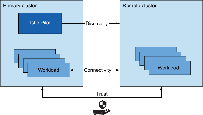
Figure 12.1 A multi-cluster service mesh requires cross-cluster discovery, connectivity, and common trust.
Fulfilling those criteria ensures that clusters are aware of the workloads running in other clusters, that workloads can connect to each other, and that workloads can authenticate and authorize using Istio policies. All of those are preconditions to setting up a multi-cluster service mesh.
12.2.1 Istio multi-cluster deployment models
We distinguish between two types of clusters in multi-cluster service meshes:
-
Primary cluster—The cluster in which Istio’s control plane is installed
-
Remote cluster—The cluster that is remote to the control-plane installation
Based on the availability we want to achieve, we have the following deployment models: primary-remote (shared control plane), primary-primary (replicated control plane), and external control plane.
The primary-remote deployment model (see figure 12.2) has a single control plane managing the mesh, and for that reason, it’s often referred to as the single control plane or shared control plane deployment model. This model uses fewer resources; however, an outage in the primary cluster affects the entire mesh. As such, it has low availability.
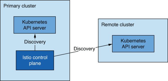
Figure 12.2 Primary-remote deployment model
The primary-primary deployment model (see figure 12.3) has multiple control planes, which ensures higher availability but has the trade-off of requiring more resources. This improves availability as outages are scoped to the clusters in which they occur. We refer to this model as the replicated control plane deployment model.

Figure 12.3 Primary-primary deployment model
The external control plane (see figure 12.4) is a deployment model where all clusters are remote to the control plane. This deployment model enables cloud providers to provide Istio as a managed service.

Figure 12.4 The external control plane deployment model
12.2.2 How workloads are discovered in multi-cluster deployments
Istio’s control plane needs to talk to the Kubernetes API server to gather relevant information to configure the service proxies, such as services and endpoints behind those services. Making requests to the Kubernetes API server is sort of a superpower, as you can look up resource details, query sensitive information, and update or delete resources to the degree of setting the cluster in a bad and irreversible state.
NOTE Although we will cover securing access to a remote Kubernetes API using tokens and role-based access control (RBAC), an astute reader must consider the trade-offs of this approach. See the previous section for how mesh federation can mitigate this risk.
Kubernetes secures access to the API server using RBAC. Kubernetes RBAC is a broad topic—and out of the scope of this book—but we can highlight some of the concepts used to facilitate cross-cluster discovery:
-
Service accounts provide identity to non-human clients such as machines or services.
-
Service account tokens are automatically generated for every service account and represent its identity claim. Tokens are formatted as JSON Web Tokens and are injected by Kubernetes into Pods that can use the tokens to authenticate to the API server.
-
Roles and cluster roles define the set of permissions for identity, such as a service account or a regular user.
Figure 12.5 visualizes the Kubernetes resources that provide authentication and authorization to istiod.

Figure 12.5 Resources that configure the identity and access of istiod
Cross-cluster workload discovery is technically the same. However, as shown in figure 12.6, we need to provide istiod with the service account token of the remote cluster (along with the certificates to initiate a secure connection to the API server, as we see when we get to the concrete examples). istiod uses the token to authenticate to remote clusters and discover workloads running in them.

Figure 12.6 istiod uses the service account credential to query the workload information of the second cluster.
This may sound like an arduous process, but there is nothing to worry about. istioctl automates the process, as we see later in the chapter.
12.2.3 Cross-cluster workload connectivity
The other precondition is that workloads have cross-cluster connectivity. When clusters are in a flat network, such as sharing a single network (like Amazon VPC), or when their networks are connected using network peering, workloads can connect using IP addresses, and the condition is already met! However, when clusters are in different networks, we have to use special Istio ingress gateways that are located at the edge of the network and proxy cross-cluster traffic. Ingress gateways that bridge clusters in multi-network meshes are known as east-west gateways (see figure 12.7). We’ll elaborate on east-west gateways later in this chapter.
12.2.4 Common trust between clusters
The last factor we need to resolve is that clusters in a multi-cluster service mesh must have common trust. Having common trust ensures that workloads of opposite clusters can mutually authenticate. There are two methods to achieve common trust between workloads of opposite clusters. The first uses what we call plug-in CA certificates: user-defined certificates issued from a common root CA. The second integrates an external CA that both clusters use to sign certificates.
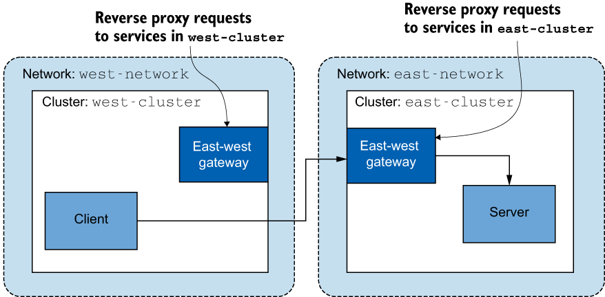
Figure 12.7 East-west gateways reverse proxy requests to the workloads in their respective clusters.
Using plug-in intermediate CA certificates is easy! Instead of letting Istio generate an intermediate CA, you specify the certificate to be used by providing it as a secret on the Istio installation namespace. You do so for both clusters and use intermediate CAs that were both signed by the common root CA. This approach is visualized in figure 12.8.
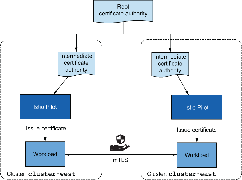
Figure 12.8 Using intermediate CA certificates that are signed by the same root
This method is favorable due to its simplicity; however, it poses a security risk if the intermediate CAs are exposed. Attackers can use them to sign certificates that are trusted until the exposure is detected and the intermediate CA’s certificate is revoked. For this reason, organizations are reluctant to hand over intermediate CAs. The exposure risk can be reduced by only loading the intermediate CAs into memory and not persisting them as Kubernetes secrets into etcd (the datastore where Kubernetes resources such as secrets are stored). An even safer alternative is to integrate an external CA that signs the certificates.
External certificate authority integration
In this solution, istiod acts as a registration authority that validates and approves certificate signing requests (CSRs) stored as Kubernetes CSRs. The Kubernetes CSRs that are approved are submitted to the external CA in one of the following ways:
-
Using cert-manager—Only viable when our external CA is supported by cert-manager (see the supported external issuers: https://cert-manager.io/docs/configuration/external). If that’s the case, then with cert-manager’s istio-csr, we can listen for Kubernetes CSRs and submit them to the external CA for signing. This is discussed in more detail in Jetstack’s blog post at www.jetstack.io/blog/cert-manager-istio-integration.
-
Custom development—Create a Kubernetes controller that listens for approved Kubernetes CSRs and submits them to an external CA for signing. Istio’s documentation on using custom CAs (http://mng.bz/p2JG) can be used as a starting point; however, the solution needs to be adapted to use an external CA instead of self-signing certificates with local keys. After the external CA signs the certificate, it is stored in the Kubernetes CSR, which
istiodforwards to the workload using the Secret Discovery Service (SDS).
In this chapter, we set up common trust between clusters using plug-in CA certificates, because it’s simpler and maintains focus on multi-cluster service meshes. We have now covered at a high level all the required conditions to set up a multi-cluster service mesh.
12.3 Overview of a multi-cluster, multi-network, multi-control-plane service mesh
We’ll set up an infrastructure that mimics real-world enterprise services running in multiple clusters, deployed across different regions, and located in different networks. The infrastructure consists of the following (see figure 12.9):
-
west-cluster—Kubernetes cluster with its private network in the us-west region. This is where we’ll run thewebappservice. -
east-cluster—Kubernetes cluster with its private network in the us-east region. This is where we’ll run thecatalogservice.
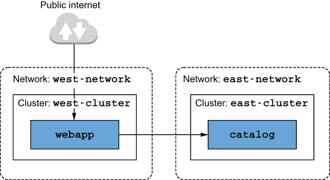
Figure 12.9 Diagram of the multi-cluster service mesh
Having the clusters in two different regions protects us from service outages when disasters occur in one of them. There is no technical reason for the webapp and catalog workloads to be in separate clusters—this is only for demonstration purposes. Whenever possible, workloads that are “chatty” should be in close proximity to reduce latency.
12.3.1 Choosing the multi-cluster deployment model
The multi-network infrastructure dictates that we need to use an east-west gateway to bridge the networks to achieve cross-cluster connectivity but leaves open the decision whether to use the replicated control-plane deployment model or a single control plane. The decision is driven by the business requirements. In ACME’s case, its online store is highly popular: every minute of it being down would cost the business millions, for real! Hence high availability is a top priority, and we’ll use the primary-primary deployment model, where the Istio control plane is deployed in each cluster. Putting it all together, we’ll set up a multi-cluster, multi-network, multi-control-plane service mesh using an east-west gateway to bridge the networks and use the primary-primary deployment model. Let’s get started!
12.3.2 Setting up the cloud infrastructure
For multi-clusters, local environments won’t suffice; we have to use a cloud provider. In the examples that follow, we use Azure. However, you can follow along as soon as you set up two Kubernetes clusters in separate networks in any cloud provider.
The infrastructure consists of two Kubernetes clusters, each located on a different network (see figure 12.9). Their creation is automated with the following script. To execute the script, you need to install the Azure CLI (see http://mng.bz/OG1n) and sign in to get access to your subscription (see http://mng.bz/YgAN). After completing the prerequisites, execute the script to create the infrastructure:
$  sh ch12/scripts/create-clusters-in-azure.sh

== Creating clusters ==
Done

== Configuring access to the clusters for `kubectl` ==
Merged "west-cluster" as current context in ~/.kube/config
Merged "east-cluster" as current context in ~/.kube/config
This script creates the clusters and configures the kubectl command-line tool with two contexts: west-cluster and east-cluster. You can specify the context when executing kubectl commands:
$  kubectl --context="west-cluster" get pods -n kube-system
$  kubectl --context="east-cluster" get pods -n kube-system
Each command prints the list of running Pods in the respective cluster, confirming that the clusters are set up correctly. Let’s create some aliases to save us keystrokes by not having to type the context all the time:
$  alias kwest='kubectl --context="west-cluster"'
$  alias keast='kubectl --context="east-cluster"'
With the aliases kwest and keast, the previous commands are reduced to
kwest get pods -n kube-system
keast get pods -n kube-system
Much neater! With the infrastructure created, the next step is to set up intermediate certificates and establish common trust between clusters.
12.3.3 Configuring plug-in CA certificates
In chapter 9, when we covered bootstrapping of workload identity—which is how workloads get a signed certificate that proves their identity—for simplicity we omitted the fact that Istio generates a CA to sign the certificates upon installation. This generated CA is stored as a secret named istio-ca-secret in the Istio installation namespace and is shared with istiod replicas. The default behavior can be overridden by plugging in our CA, which the Istio CA picks up instead of generating a new one. To do so, we have to store the CA certificates as a secret named cacerts in the installation namespace istio-system, containing the following data (see figure 12.10):
-
root-cert.pem—The root CA’s certificate that issued the intermediate CA. The root CA validates the certificates issued by any of its intermediate CAs, which is key for mutual trust across clusters. -
cert-chain.pem—The concatenation of the intermediate CA’s certificate and the root CA certificate that forms the trust chain.
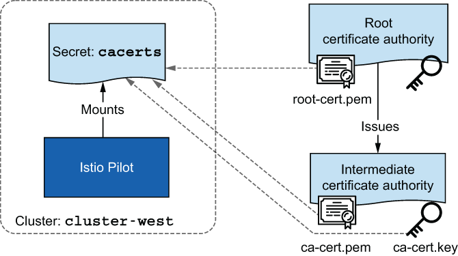
Figure 12.10 The cacerts secret is composed of the root CA’s public key and the intermediate CA’s public and private keys. The private key of the root CA is stored securely outside of the cluster.
For your convenience, the intermediate CAs and the root CA are created in the directory ./ch12/certs. They are generated using the script ./ch12/scripts/generate-certificates.sh, which creates a root CA and uses it to sign two intermediate CA certificates. This results in two intermediate CAs that have common trust.
Applying plug-in CA certificates
Configure the intermediate CAs in each cluster by creating the istio-system namespace and then applying the certificates as secrets named cacerts:
$  kwest create namespace istio-system                      ❶
$  kwest create secret generic cacerts -n istio-system     ❶
       --from-file=ch12/certs/west-cluster/ca-cert.pem     ❶
       --from-file=ch12/certs/west-cluster/ca-key.pem      ❶
       --from-file=ch12/certs/root-cert.pem                ❶
       --from-file=ch12/certs/west-cluster/cert-chain.pem   ❶

$  keast create namespace istio-system                      ❷
$  keast create secret generic cacerts -n istio-system     ❷
       --from-file=ch12/certs/east-cluster/ca-cert.pem     ❷
       --from-file=ch12/certs/east-cluster/ca-key.pem      ❷
       --from-file=ch12/certs/root-cert.pem                ❷
       --from-file=ch12/certs/east-cluster/cert-chain.pem   ❷
❶ Setting up certificates for the west-cluster
❷ Setting up certificates for the east-cluster
With the plug-in certificates configured, we can install the Istio control plane, which picks up the plug-in CA certificates (the user-defined intermediate certificates) to sign workload certificates.
12.3.4 Installing the control planes in each cluster
Before installing Istio’s control plane, let’s add network metadata for each cluster. Network metadata enables Istio to utilize the topology information and configure workloads based on it. Thus workloads can use locality information and prioritize routing traffic to workloads in close proximity. Another benefit when Istio understands the network topology is that it configures workloads to use east-west gateways when routing traffic to workloads in remote clusters that are in different networks.
Labeling networks for cross-cluster connectivity
The network topology can be configured within the Istio installation using the MeshNetwork configuration (http://mng.bz/GG6q). However, it’s a legacy piece of configuration kept only for rare and advanced use cases. The simpler option is to label the Istio installation namespace with network topology information. For us, the Istio installation namespace is istio-system, and the network in the west-cluster is west-network. Thus we label the istio-system in the west-cluster with topology .istio.io/network=west-network:
$  kwest label namespace istio-system
     topology.istio.io/network=west-network
And for the east-cluster, we set the network topology label to east-network:
$  keast label namespace istio-system
     topology.istio.io/network=east-network
With these labels, Istio forms an understanding of the network topology and uses it to decide how to configure workloads.
Installing the control planes using IstioOperator resources
Because we have to make numerous modifications, we are going to use an IstioOperator resource to define the Istio installations for the west-cluster:
apiVersion: install.istio.io/v1alpha1
metadata:
 name: istio-controlplane
 namespace: istio-system
kind: IstioOperator
spec:
  profile: demo
  components:
    egressGateways:                ❶
    - name: istio-egressgateway
      enabled: false
 values:
   global:
     meshID: usmesh                ❷
     multiCluster:
       clusterName: west-cluster   ❸
network: west-network ❹❸ Cluster identifier in the multi-cluster mesh
❹ Network in which this installation is occurring
NOTE Kubernetes clusters can have many tenants and can span many teams. Istio provides the option of installing multiple meshes within a cluster, allowing teams to manage their mesh operations separately. The meshID property enables us to identify the mesh to which this installation belongs.
The previous definition is stored in the file ch12/controlplanes/cluster-west.yaml, and you can install Istio with that configuration using istioctl:
$  istioctl --context="west-cluster" install -y
     -f ch12/controlplanes/cluster-west.yaml

✔ Istio core installed
✔ Istiod installed
✔ Ingress gateways installed
✔ Installation complete
After a successful installation of the west-cluster, you can install the replicated control plane in the east-cluster. The IstioOperator definition for the east-cluster differs from that of the west-cluster only in the cluster name and the network. And because we want both control planes to form the same mesh, we specify the same meshID that we used for the west-cluster installation:
apiVersion: install.istio.io/v1alpha1
metadata:
  name: istio-controlplane
  namespace: istio-system
kind: IstioOperator
spec:
  profile: demo
  components:
    egressGateways:
    - name: istio-egressgateway
      enabled: false
  values:
    global:
      meshID: usmesh
      multiCluster:
        clusterName: east-cluster
      network: east-network
Next, we install the control plane in the east-cluster:
$  istioctl --context="east-cluster" install -y
      -f ch12/controlplanes/cluster-east.yaml

✔ Istio core installed
✔ Istiod installed
✔ Ingress gateways installed
✔ Installation complete
Before moving on, let’s create aliases for the different cluster contexts in istioctl, as we did for kubectl earlier:
$  alias iwest='istioctl --context="west-cluster"'
$  alias ieast='istioctl --context="east-cluster"'
After installing the control planes on both clusters, we have two separate meshes—each running one istiod replica that discovers only local services—and a gateway for ingress traffic (see figure 12.11).

Figure 12.11 Current setup of the meshes
The meshes lack cross-cluster workload discovery and connectivity, which we set up in the following sections. But before proceeding, let’s run some workloads in each cluster. The workloads will come in handy to verify that cross-cluster discovery and connectivity are set up correctly.
Running workloads on both clusters
With the control planes installed, let’s run some workloads. In the west-cluster, we deploy webapp:
$  kwest create ns istioinaction
$  kwest label namespace istioinaction istio-injection=enabled
$  kwest -n istioinaction apply -f ch12/webapp-deployment-svc.yaml
$  kwest -n istioinaction apply -f ch12/webapp-gw-vs.yaml
$  kwest -n istioinaction apply -f ch12/catalog-svc.yaml       ❶
❶ Stub catalog service to which webapp makes requests
In this listing, almost everything makes sense. For example, we create a namespace and label it for auto-injection so that workloads get the sidecar proxies injected. Then we deploy the webapp, including a service for it, and expose this service from the ingress gateway by admitting traffic using a Gateway resource and routing traffic to it with a VirtualService resource.
But why do we need a service for the catalog workload, considering that we want to run it only in the east-cluster? The reason for adding this stub service is that in its absence, the webapp container cannot resolve the fully qualified domain name (FQDN) to any IP address, and thus the request would fail prior to reaching the point where traffic leaves the application and is redirected to the proxy. By adding a stub catalog service, the FQDN is resolved to the service cluster IP and traffic is initiated by the application, which makes it possible for it to be redirected to the Envoy proxy where the actual Envoy configuration exists and handles the cross-cluster routing. This is an edge case that the Istio community plans to fix in upcoming versions when the DNS proxy is enhanced further, which is a topic we will examine in the next chapter.
Let’s install the catalog service in the east-cluster:
$  keast create ns istioinaction
$  keast label namespace istioinaction istio-injection=enabled
$  keast -n istioinaction apply -f ch12/catalog.yaml
Suppose this is our starting point: two clusters, each with workloads that need to connect. But without cross-cluster workload discovery, the sidecar proxies are not configured for the workloads in opposite clusters. Thus our next step is enabling cross-cluster discovery.
12.3.5 Enabling cross-cluster workload discovery
For Istio to be authenticated for querying information from the remote cluster, it needs a service account that defines the identity and role bindings for its permissions. For this reason, Istio, upon installation, creates a service account (named istio-reader-service-account) with the minimal set of permissions that can be used by another control plane to authenticate itself and look up workload-related information such as services and endpoints. However, we need to make the service account token available to the opposite cluster, along with certificates to initiate a secure connection to the remote cluster.
Creating the secrets for remote cluster access
The istioctl utility has the create-remote-secret command, which by default creates the secret for remote cluster access using the default istio-reader-service-account service account. When creating the secret, it’s important to specify the name of the cluster as specified during Istio installation in the IstioOperator (see the earlier listings for the west-cluster and the east-cluster in the section “Installing the control planes using IstioOperator resources”). Pay attention to how the cluster name is used as an identifier for the configuration to access the remote clusters:
$  ieast x create-remote-secret --name="east-cluster"

# This file is autogenerated, do not edit.
apiVersion: v1
kind: Secret
metadata:
  annotations:
    networking.istio.io/cluster: east-cluster
  labels:
    istio/multiCluster: "true"                       ❶
  name: istio-remote-secret-east-cluster
  namespace: istio-system
stringData:
  east-cluster: |
    apiVersion: v1
    kind: Config
    preferences: {}
    clusters:
    - cluster:
        certificate-authority-data: <omitted>        ❷
        server: https://east-clust-dkjqiu.hcp.eastus.azmk8s.io:443
      name: east-cluster
    users:
    - name: east-cluster
      user:
        token: <omitted>                             ❸
    contexts:
    - context:
        cluster: east-cluster
        user: east-cluster
      name: east-cluster
    current-context: east-cluster
❶ Secrets with this label set to true are watched by Istio’s control plane to register new clusters.
❷ CA used to initiate a secure connection to this cluster
❸ Token that represents the identity of the service account
Instead of printing the secret, let’s pipe it to the kubectl command and apply it to the west-cluster:
$  ieast x create-remote-secret --name="east-cluster"
   | kwest apply -f -

secret/istio-remote-secret-east-cluster created
As soon as the secret is created, istiod picks it up and queries workloads in the newly added remote cluster. This is logged in istiod, as shown in its logs:
$ kwest logs deploy/istiod -n istio-system | grep 'Adding cluster'

2021-04-08T08:47:32.408052Z     info
➥Adding cluster_id=east-cluster from
➥secret=istio-system/istio-remote-secret-east-cluster
The logs verify that the cluster is initialized and that the west-cluster control plane can discover workloads in the east-cluster. For a primary-primary deployment, we need to do the opposite as well, configuring the east-cluster to query the west-cluster:
$  iwest x create-remote-secret --name="west-cluster"
   | keast apply -f -

secret/istio-remote-secret-west-cluster created
Now the control planes can query the workloads on the opposite clusters. Does that mean we are done? Not yet! But we are one step closer. Next, we set up cross-cluster connectivity.
12.3.6 Setting up cross-cluster connectivity
In chapter 4, we discussed Istio’s ingress gateway and saw that it’s based on the Envoy proxy. It represents the ingress point for traffic originating in the public network and is directed to the organization’s internal network. This type of traffic is often referred to as north-south traffic. In contrast, traffic between different internal networks—in our instance, the networks of the clusters—is known as east-west traffic (see figure 12.12).

Figure 12.12 North-south and east-west traffic
To simplify east-west traffic, most cloud providers enable peering of virtual networks—provided the network address spaces do not overlap. Services in peered virtual networks initiate direct connections using IPv4 and IPv6 addresses. However, network peering is a cloud-specific feature. Whenever we want to connect clusters in different cloud providers or on-premises where network peering is not possible, the option Istio provides is an east-west gateway. The gateway must be exposed with a load balancer that’s accessible to the workloads of the opposite clusters.
In this section, we set up cross-cluster connectivity and show how it works under the hood. It may seem complicated, but we believe understanding how this works is more important than just making it work. If things go wrong, you should have the knowledge and ability to troubleshoot and restore connectivity.
The east-west gateway’s goal, in addition to being an ingress point for cross-cluster east-west traffic, is to make this process transparent from the teams operating the services. To meet this goal, the gateway must
And service mesh operators shouldn’t have to configure any additional resources! In other words, you shouldn’t have to configure any additional Istio resources! This ensures that there is no difference when routing in-cluster or cross-cluster traffic. In both scenarios, workloads can target services in a fine-grained manner and can initiate mutually authenticated connections. (One nuance is what happens to load balancing when it crosses a cluster boundary. We explore that in the next section.) To understand how this is implemented, we need to introduce two of Istio’s features—SNI clusters and SNI auto passthrough—and how they modify the gateway’s behavior.
Configuring east-west gateways with SNI clusters
East-west gateways are ingress gateways with additional configuration for Server Name Indication (SNI) clusters for every service. But what are SNI clusters? SNI clusters are just like regular Envoy clusters (see chapter 10, section 10.3.2, Querying the Envoy Cluster Configuration subsection), consisting of the direction, subset, port, and FQDN that group a set of similar workloads where traffic can be routed. However, SNI clusters have one key difference: they encode all Envoy cluster information in the SNI. This enables the east-west gateway to proxy encrypted traffic to the cluster specified by the client within the SNI. To take a concrete example, when one client—such as the webapp—initiates a connection to a workload in a remote cluster—such as the catalog workload—it encodes the cluster that it targets into the SNI, as shown in figure 12.13.

Figure 12.13 (1) Cluster information is encoded into the SNI. (2) The SNI contains the direction, port, version, and service name that dictates routing decisions.
Thus the client can make fine-grained routing decisions, and the gateway can read the cluster information from the SNI header and then proxy the traffic to the workload intended by the client. All this happens while maintaining a secure and mutually authenticated connection between the workloads.
Installing the east-west gateway with SNI clusters
For a gateway, the configuration of SNI clusters is an opt-in feature that can be enabled by setting the gateway router mode to sni-dnat using the environment variable ISTIO_META_ROUTER_MODE, as shown in the following IstioOperator definition:
apiVersion: install.istio.io/v1alpha1
kind: IstioOperator
metadata:
  name: istio-eastwestgateway                          ❶
  namespace: istio-system
spec:
  profile: empty                                       ❷
  components:
    ingressGateways:
    - name: istio-eastwestgateway                      ❸
      label:
        istio: eastwestgateway
        app: istio-eastwestgateway
      enabled: true
      k8s:
        env:
          - name: ISTIO_META_ROUTER_MODE               ❹
            value: "sni-dnat"                          ❹
          - name: ISTIO_META_REQUESTED_NETWORK_VIEW    ❺
            value: east-network                        ❺
        service:
          ports:
            # redacted for brevity
  values:
    global:
      meshID: usmesh                                   ❻
      multiCluster:                                    ❻
        clusterName: east-cluster                      ❻
      network: east-network                            ❻
❶ The IstioOperator name should not overlap the previous Istio installation.
❷ The empty profile doesn’t install additional Istio components.
❹ The sni-dnat mode adds the SNI clusters required for proxying traffic.
❺ Network in which the gateway routes traffic
❻ Mesh, cluster, and network identifying information
There is quite a lot to unravel in this definition:
-
The name of the
IstioOperatorresource must not be the same as the resource initially used to install the control plane. If the same name is used, the previous installation will be overwritten. -
Setting
ISTIO_META_ROUTER_MODEtosni-dnatconfigures SNI clusters automatically. When not specified, it falls back to thestandardmode, which doesn’t configure SNI clusters. -
ISTIO_META_REQUESTED_NETWORK_VIEWdefines the network traffic is proxied to.
Install the east-west gateway using the previous IstioOperator definition, which is located in the file ch12/gateways/cluster-east-eastwest-gateway.yaml:
$  ieast install -y -f ch12/gateways/cluster-east-eastwest-gateway.yaml

✔ Ingress gateways installed
✔ Installation complete
With the east-west gateway installed and the router mode set to sni-dnat the next step is to expose the multi-cluster mTLS port through the east-west gateway using the SNI auto passthrough mode. Istio is clever and only then configures the gateway with the SNI clusters.
Routing cross-cluster traffic using SNI auto passthrough
To understand SNI auto passthrough, let’s recall that the manual SNI passthrough configures the ingress gateway to admit traffic based on the SNI header (see chapter 4, section 4.4.2). This shows that to route admitted traffic, service operators have to manually define a VirtualService resource (see figure 12.14). SNI auto passthrough, as the name suggests, doesn’t require manually creating a VirtualService to route admitted traffic. It is done using the SNI clusters, which are configured automatically in the east-west gateway when its router mode is set to sni-dnat (figure 12.15).
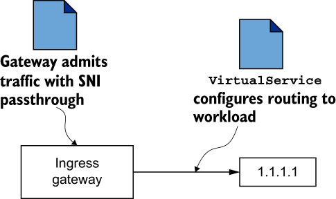
Figure 12.14 Traffic routing with SNI passthrough requires defining VirtualService resources.

Figure 12.15 Traffic routing with SNI auto passthrough uses SNI clusters initialized in the sni-dnat router mode.
SNI auto passthrough mode is configured using the Istio Gateway resource. In the following definition, we use SNI auto passthrough for all traffic where the SNI header matches the expression *.local, which is the case for all Kubernetes services:
apiVersion: networking.istio.io/v1alpha3
kind: Gateway
metadata:
  name: cross-network-gateway
  namespace: istio-system
spec:
  selector:
    istio: eastwestgateway        ❶
  servers:
    - port:
        number: 15443             ❷
        name: tls
        protocol: TLS
      tls:
        mode: AUTO_PASSTHROUGH    ❸
      hosts:
        - "*.local"               ❹
❶ Configuration is applied only to gateways matching the selector.
❷ In Istio, port 15443 is a special port designated for multi-cluster mTLS traffic.
❸ Resolves the destination using the SNI header and uses the SNI clusters
❹ Admits traffic only for SNIs matching the regex *.local
This resource is defined in the file ch12/gateways/expose-services.yaml. Applying it to the cluster exposes workloads of the east-cluster to the west-cluster:
$  keast apply -n istio-system -f ch12/gateways/expose-services.yaml

gateway.networking.istio.io/cross-network-gateway created
Before moving on, let’s do the opposite as well: create an east-west gateway in the west-cluster and expose its services to the workloads in the east-cluster:
$  iwest install -y -f ch12/gateways/cluster-west-eastwest-gateway.yaml
$  kwest apply -n istio-system -f ch12/gateways/expose-services.yaml
Now, let’s verify that SNI clusters are configured by querying the cluster proxy configuration of the east-west gateway and filtering the output to only lines containing the catalog text:
$  ieast pc clusters deploy/istio-eastwestgateway.istio-system
    | grep catalog | awk '{printf "CLUSTER: %s
", $1}'

CLUSTER: catalog.istioinaction.svc.cluster.local
CLUSTER: outbound_.80_._.catalog.istioinaction.svc.cluster.local    ❶
❶ SNI cluster for the catalog service
The output shows the SNI cluster is defined for the catalog workload! And as we configured the gateway with SNI auto passthrough, incoming traffic on the gateway uses the SNI clusters to route to the intended workloads. Istio’s control plane listens for the creation of these resources and discovers that now a path exists to route cross-cluster traffic. Thus it updates all workloads with the newly discovered endpoints in the remote cluster.
Validating cross-cluster workload discovery
Now, as the workloads in the east-cluster are exposed to the west-cluster, we expect that the Envoy clusters of the webapp have an endpoint to the catalog workload. This endpoint should point to the east-west gateway’s address, which proxies the request to the catalog workload in its network. To check this, let’s get the address of the east-west gateway in the east-cluster:
$  keast -n istio-system get svc istio-eastwestgateway
      -o jsonpath='{.status.loadBalancer.ingress[0].ip}'

40.114.190.251
Now, let’s compare it to the address that the workloads in the west-cluster use when routing cross-cluster traffic:
In figure 12.16 we show our output of the previous command.

Figure 12.16 The catalog endpoint refers to the east-west gateway multi-cluster port
If the endpoint of the catalog resource matches the address of the east-west gateway, then the workloads are discovered, and cross-cluster traffic is possible. Considering the proxy configuration, everything is set up correctly. Let’s trigger a request manually and make this the final validation:
$  EXT_IP=$(kwest -n istio-system get svc istio-ingressgateway
     -o jsonpath='{.status.loadBalancer.ingress[0].ip}')

$  curl http://$EXT_IP/api/catalog -H "Host: webapp.istioinaction.io"

[
  {
    "id": 0,
    "color": "teal",
    "department": "Clothing",
    "name": "Small Metal Shoes",
    "price": "232.00"
  }
]
Hooray! We see that when we triggered a request to the ingress gateway, it was routed to the webapp in the west-cluster. Then it was resolved to the catalog workload in the east-cluster, which in the end served the request. With that, we have validated that the multi-cluster, multi-network, multi-control plane service mesh is set up and workloads are discovered across clusters; they can initiate mutually authenticated connections using east-west gateways as a passthrough.
Let’s recap what was required to set up a multi-cluster service mesh:
-
Cross-cluster workload discovery by providing each control plane with access to the peer cluster, using the
kubeconfigcontaining the service account token and certificates. The process was facilitated usingistioctl, and we only applied it to the opposite clusters. -
Cross-cluster workload connectivity by configuring east-west gateways to route traffic between workloads in different clusters (that reside in different networks) and labeling each cluster with network information so that Istio knows the network workloads reside in.
-
Configuring trust between clusters by using a common root of trust that issues the intermediate certificates of the opposite clusters.
That’s just a few steps, and they are mostly automated to set up multi-cluster service meshes. In the next section, let’s verify some of the service-mesh behaviors across clusters.
12.3.7 Load-balancing across clusters
In chapter 6, we promised to explore cross-cluster, locality-aware load balancing. And now, with the multi-cluster service mesh at hand, we are ready to do so. To demonstrate this, we’ll deploy two sample services, each of which is configured to return the name of the cluster in which the workload is running. Thus we can easily determine the locality of the workload that served the request.
Let’s deploy the first service in the west-cluster:
$  kwest apply -f                                      ❶
ch12/locality-aware/west/simple-backend-deployment.yaml

$  kwest apply -f
ch12/locality-aware/west/simple-backend-svc.yaml        ❷

$  kwest apply -f
ch12/locality-aware/west/simple-backend-gw.yaml         ❸

$  kwest apply -f
ch12/locality-aware/west/simple-backend-vs.yaml         ❹
❶ Deploys a simple backend deployment in the west-cluster
❷ Kubernetes service for the simple backend deployment
❸ Applies a Gateway resource to admit traffic
❹ Applies a VirtualService resource that routes traffic from the Gateway to the simple backend workloads
As soon as the resources are created, we make a request to the service in the west-cluster and see that it returns the cluster name:
$  curl -s $EXT_IP -H "Host: simple-backend.istioinaction.io" | jq ".body"

"Hello from WEST"
Now we can deploy the service in the east-cluster:
$  keast apply -f ch12/locality-aware/east/simple-backend-deployment.yaml
$  keast apply -f ch12/locality-aware/east/simple-backend-svc.yaml
With the services running in both clusters, their endpoints are configured in the ingress gateway, and requests are load-balanced between them (see figure 12.17).

Figure 12.17 Cross-cluster load balancing
By default, Istio load-balances between workloads using the round-robin algorithm. Thus traffic is load-balanced equally:
$  for i in {1..10}; do curl --max-time 5 -s $EXT_IP
    -H "Host: simple-backend.istioinaction.io" | jq .body; done

"Hello from EAST"
"Hello from WEST"
<...>
That’s good! However, performance can be improved further using locality-aware load balancing so workloads prioritize routing traffic to workloads within their locality. We mentioned in previous chapters that cloud providers add the locality information into nodes as labels. Istio uses this information retrieved from the labels to configure the locality of workloads.
Verifying locality-aware routing across clusters
Because we created the multi-cluster service mesh in Azure, the nodes are labeled with locality information from the cloud provider, as shown in this output:
$ kwest get nodes -o custom-columns="
NAME:{.metadata.name},
REGION:{.metadata.labels.topology.kubernetes.io/region},
ZONE:{metadata.labels.topology.kubernetes.io/zone}"         ❶

NAME                                REGION   ZONE
aks-nodepool1-31209271-vmss000003   westus   0
❶ Formats the output to show the node name, region, and zone
As expected, the node in the west-cluster is labeled with the westus region. Checking the east-cluster shows the eastus region. This information is picked up by istiod and propagated to the workloads when configuring the endpoints:
$ iwest pc endpoints deploy/istio-ingressgateway.istio-system
    --cluster
    'outbound|80||simple-backend.istioinaction.svc.cluster.local'
    -o json

[{
  "name": "outbound|80||simple-backend.istioinaction.svc.cluster.local",
  "addedViaApi": true,
  "hostStatuses": [
      {
          "address": <omitted>,
          "stats": <omitted>,
          "healthStatus": {
              "edsHealthStatus": "HEALTHY"
          },
          "weight": 1,
          "locality": {
              "region": "westus",    ❶
              "zone": "0"            ❶
          }
      },
      {
          "address": <omitted>,
          "stats": <omitted>,
          "healthStatus": {
              "edsHealthStatus": "HEALTHY"
          },
          "weight": 1,
          "locality": {
              "region": "eastus",    ❷
              "zone": "0"            ❷
          }
      }
  ],
  "circuitBreakers": <omitted>
}]
❶ Locality information of the workload in the west-cluster
❷ Locality information of the workload in the east-cluster
The output shows that both endpoints have locality information. Recall from chapter 6 that in order for Istio to use locality information, passive health checking is required. Let’s apply a destination rule that uses outlier detection to passively check the health of the endpoints:
After the configuration propagates, which usually takes a couple of seconds, we can verify that requests use the locality information and are routed within the same cluster:
$  for i in {1..10}; do curl --max-time 5 -s $EXT_IP
      -H "Host: simple-backend.istioinaction.io" | jq .body; done

"Hello from WEST"
"Hello from WEST"
"Hello from WEST"
<...>
As expected, all requests are routed within the west-cluster, which is the closest to the ingress gateway that’s routing the traffic. Because all the routing decisions are made in the Envoy proxy, we can conclude that the control plane must have modified its configuration, which explains the different behavior. Let’s see how the configuration was modified by printing it again:
$  iwest pc endpoints deploy/istio-ingressgateway.istio-system
      --cluster
      'outbound|80||simple-backend.istioinaction.svc.cluster.local'
      -o json

[{
  "name": "outbound|80||simple-backend.istioinaction.svc.cluster.local",
  "addedViaApi": true,
  "hostStatuses": [
      {
          <omitted>
          "weight": 1,
          "locality": {
              "region": "westus",
              "zone": "0"
          }
      },
      {
          <omitted>
          "weight": 1,
          "priority": 1,    ❶
          "locality": {
              "region": "eastus",
              "zone": "0"
          }
      }
  ],
  "circuitBreakers": <omitted>
}]
❶ Priority of 1 for the second host
Now we see the priority field that specifies the priority for traffic to be routed to this host. The highest priority is 0 (the default, when not specified)—that is why it’s missing from the host in westus, which has the highest priority. A value of 1 has a lower priority, and so on. When hosts with the highest priority are unavailable, traffic is routed to those with a lower priority. Let’s verify this.
Verifying cross-cluster failover
To simulate that the simple backend deployment is failing, we can configure it to fail requests by setting the environment variable ERROR_RATE to 1. Let’s do so for the workload in the west-cluster:
$  kwest -n istioinaction set env
      deploy simple-backend-west ERROR_RATE='1'
After some time passes, outlier detection detects that the host is unhealthy and routes traffic to the workload in the east-cluster, which has the second-highest priority:
$  for i in {1..10}; do curl --max-time 5 -s $EXT_IP
      -H "Host: simple-backend.istioinaction.io" | jq .body; done

"Hello from EAST"
"Hello from EAST"
"Hello from EAST"
<...>
This shows the cross-cluster failover in action: traffic was routed to the east-cluster because the workloads with the highest priority failed the passive health checks.
NOTE As seen in this detailed walkthrough, cross-cluster traffic traverses the opposite cluster’s east-west gateway and is treated as an SNI passthrough. This has implications for load balancing once traffic reaches the remote cluster. Since this call is an SNI/TCP connection and the gateway does not terminate the TLS connection, the east-west gateway can only forward the connection as is to the backend service. This opens a connection from the east-west gateway to the backend service and does not have request-level load-balancing capabilities. Thus, on failover or load balancing across multiple clusters, the load is balanced or failed over from the client’s point of view but not necessarily balanced evenly across all instances on the remote cluster.
Verifying cross-cluster access control using authorization policies
The last feature we will verify is access control across clusters. Recall that access control requires that traffic is mutually authenticated between workloads, producing reliable metadata that can be used to decide whether to admit or deny traffic. To demonstrate this, let’s come up with a scenario. Suppose we want to admit traffic to the service only if its source is Istio’s ingress gateway; otherwise, the traffic is denied. A policy to achieve that is defined and stored in the file ch12/security/only-ingress-policy.yaml. Apply it to the east-cluster:
$  keast apply -f ch12/security/allow-only-ingress-policy.yaml

authorizationpolicy.security.istio.io/allow-only-ingress created
Before executing any requests, let’s clean up the service from the west-cluster so that only the instance in the east-cluster serves the traffic:
$ kwest delete deploy simple-backend-west -n istioinaction

deployment.apps "simple-backend-west" deleted
After the update is propagated, we can test the policy by triggering a request from a workload in the west-cluster. For that we will run a temporary Pod:
$  kubectl run -i --rm --restart=Never sleep --image=curlimages/curl
--command -- curl -s simple-backend.istioinaction.svc.cluster.local

RBAC: access denied
As expected, the request was denied. Meanwhile, triggering a request to the ingress gateway and having the request routed from the gateway results in a successful response:
$  curl --max-time 5 -s $EXT_IP
    -H "Host: simple-backend.istioinaction.io" | jq .body

"Hello from EAST"
We can see that the policy admitted the traffic originating from the ingress gateway. This shows that workloads were mutually authenticating across clusters, and policies could use the authenticated data encoded into the identity certificates for access control.
All our examples of load balancing, locality-aware routing, cross-cluster failover, mutually authenticated traffic, and access control demonstrate that workloads in multi-cluster service meshes can use all of Istio’s capabilities regardless of the cluster in which they run. And they do so without requiring any additional configuration.
NOTE Remember to clean up resources in the cloud provider. If you are using Azure, you can execute the script $ sh ch12/scripts/cleanup-azure-resources.sh.
Hopefully, this chapter has shown you how Istio can scale within your organization and incorporate multiple clusters into a single mesh and why this is important for many organizations. In the next chapter, we integrate virtual machines into the service mesh, which is a highly desirable feature for mature enterprises that have to operate legacy workloads.
Summary
-
Istio supports three multi-cluster service mesh deployment models: single control plane (primary-remote), replicated control planes (primary-primary), and external control plane.
-
We can establish common trust across clusters using plug-in CA certificates by installing intermediate certificates in the
istio-systemnamespace. -
Cross-cluster workloads are discovered in replicated control-plane deployment models using service accounts as an identity in the remote cluster and making the service account token available to the opposite cluster as a secret.
-
We can bridge the networks of multi-network service meshes using east-west gateways. The
sni-dnatrouter mode configures SNI clusters to route cross-cluster traffic in a fine-grained manner. -
The east-west gateway can be configured to auto passthrough traffic and route based on the automatically configured SNI clusters.
-
Istio’s capabilities work across clusters in the same way they do within a cluster.