Chapter 12
Windows Programming with the Microsoft Foundation Classes (MFC)
- The basic elements of an MFC-based program
- The difference between Single Document Interface (SDI) applications and Multiple Document Interface (MDI) applications
- How to use the MFC Application Wizard to generate SDI and MDI programs
- The files generated by the MFC Application Wizard and what they contain
- How an MFC Application Wizard-generated program is structured
- The key classes in an MFC Application Wizard-generated program, and how they are interconnected
- How to customize an MFC Application Wizard-generated program
You can find the wrox.com code downloads for this chapter on the Download Code tab at www.wrox.com/go/beginningvisualc. The code is in the Chapter 11 download and individually named according to the names throughout the chapter.
THE MFC DOCUMENT/VIEW CONCEPT
When you write applications using the MFC, it implies acceptance of a specific structure for your program, with application data stored and processed in a particular way. This may sound restrictive, but it really isn’t for the most part, and the benefits in speed and ease of implementation far outweigh any disadvantages. The structure of an MFC program incorporates two application-oriented entities — a document and a view — so let’s look at what they are and how they’re used.
What Is a Document?
A document is a collection of data in your application with which the user interacts. Although the word ****document seems to imply something of a textual nature, it isn’t limited to text. It could be data for a game, a geometric model, a text file, a collection of data on the distribution of orange trees in California, or, indeed, anything you want. The term document is just a convenient label for the application data in your program, treated as a unit.
You won’t be surprised to hear that a document is defined as an object of a document class. Your document class is derived from the CDocument class in the MFC library, and you add your own data members to store items that your application requires, and member functions to support processing of that data. Your application is not limited to a single document type; you can define multiple document classes when there are several different kinds of documents involved in your application.
Handling application data in this way enables standard mechanisms to be provided within the MFC for managing a collection of application data as a unit and for storing the data on disk. These mechanisms are inherited by your document class from CDocument, so you get a broad range of functionality built into your application automatically, without having to write any code.
Document Interfaces
You have a choice as to whether your program deals with just one document at a time, or with several. The Single Document Interface (SDI) is supported by the MFC for programs that require only one document to be open at a time. A program using this interface is an SDI application.
For programs needing several documents to be open at one time, you use the Multiple Document Interface (MDI). With the MDI, as well as being able to open multiple documents of one type, your program can also be organized to handle documents of different types simultaneously with each document displayed in its own window. Of course, you need to supply the code to deal with processing all the types of documents you intend to use. In an MDI application, each document is displayed in a child window of the application window. You also have an application variant called the multiple top-level document architecture where each document window is a child of the desktop.
What Is a View?
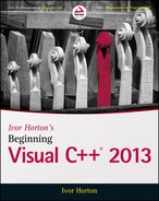
A view always relates to a particular document object. A document object contains a set of application data, and a view is an object that provides a mechanism for displaying some or all of that data. A view defines how the data is to be displayed in a window and how the user can interact with it. You define a view class by deriving it from the MFC class, CView. Note that a view object and the window, in which it is displayed, are distinct. The window in which a view appears is called a frame window. A view is displayed in its own window that exactly fills the client area of a frame window. Figure 12-1 illustrates how a document might be displayed in two views.
In Figure 12-1, each view displays all the data that the document contains in a different form, although a view could display just part of the data if that’s what’s required.
A document can have as many view objects associated with it as you want. Each view can provide a different presentation of the document data or a subset of the data. If you were dealing with text, for example, different views could display independent blocks of text from the same document. For a program handling graphical data, you could display the document data at different scales in separate windows, or in different formats, such as a textual representation of the elements that form the image. Figure 12-1 illustrates a document that contains numerical data — product sales data by month — where one view provides a bar chart representation of sales performance and a second view shows the data in the form of a graph.
Linking a Document and Its Views
The MFC incorporates a mechanism for integrating a document with its views, and each frame window with a currently active view. A document automatically maintains a list of pointers to its associated views, and a view object has a data member holding a pointer to the document to which it relates. Each frame window stores a pointer to the currently active view. The coordination between a document, a view, and a frame window is established by another MFC class of objects called document templates.
Document Templates
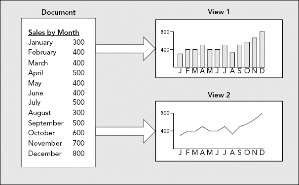
A document template manages the document objects in your program, as well as the windows and views associated with each of them. There is one document template for each type of document that you have in your application. If you have two or more documents of the same type, you need only one document template to manage them. A document template object creates document objects and frame window objects, and views for a document are created by a frame window object. The application object that is fundamental to every MFC application creates the document template object. Figure 12-2 shows a graphical representation of these interrelationships.
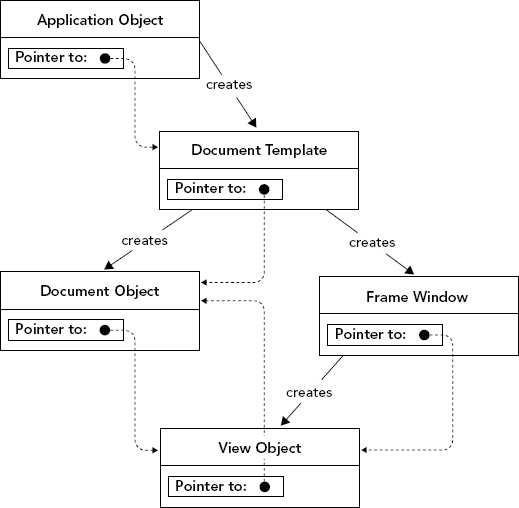
Figure 12-2 uses dashed arrows to show how pointers are used to relate objects. These pointers enable function members of one object to access the public data or function members in the interface of another object.
Document Template Classes
The MFC has two document template classes. CSingleDocTemplate is used for SDI applications. This is relatively straightforward because an SDI application has only one document and usually just one view. MDI applications are rather more complicated. They have multiple documents active at one time and the CMultiDocTemplate class defines the document template. You’ll see more of these classes as you develop application code.
Your Application and MFC
Figure 12-3 shows the four basic classes that are going to appear in virtually all your MFC-based Windows applications:
- The application class
CMyApp - The frame window class
CMyWnd - The view class
CMyView, which defines how data contained inCMyDocis to be displayed in the client area of a window created by aCMyWndobject - The document class
CMyDoc, defining a document to contain the application data
The names for these classes are specific to an application, but the derivation from the MFC is much the same, although there can be alternative base classes, particularly with the view class. The MFC provides several variations of the view class that provide a lot of prepackaged functionality, saving you lots of coding. You normally don’t need to extend the document template class so the standard CSingleDocTemplate class usually suffices in an SDI program. CMultiDocTemplate is the document template class in an MDI program and this is also derived from CDocTemplate. An MDI application also contains an additional class that defines a child window.
The arrows in Figure 12-3 point from a derived class to a base class. The MFC classes shown here form quite a complex inheritance structure, but these are just a very small part of the complete MFC structure. You need not be concerned about the details of the complete MFC hierarchy, but it is important to have a general appreciation of it if you want to understand what the inherited members of your classes are. You will not see any of the definitions of the base classes in your code, but the inherited members in a derived class are accumulated from the direct base class and each of the indirect base classes in the hierarchy. To determine what members one of your program’s classes has, you need to know from which classes it inherits. After you know that, you can look up its members using the Help facility.
You don’t need to worry about remembering which classes you need to have in your program and what base classes to use in their definition. As you’ll see next, all of this is taken care of for you by Visual C++.
CREATING MFC APPLICATIONS
You use four primary tools in the development of your MFC-based Windows programs:
- An Application Wizard for creating the basic application program code when you start. You use an Application Wizard whenever you create a project.
- The project context menu in Class View enables you to add new classes and resources to a project. You display this menu by right-clicking the project name in the Class View pane and using the Add/Class menu item to add a new class. Resources are composed of non-executable data such as bitmaps, icons, menus, and dialog boxes. The Add/Resource menu item from the same menu helps you to add a new resource.
- The class context menu in Class View enables you to extend and customize classes in your program. You use the Add/Add Function and Add/Add Variable menu items to do this.
- You use a Resource Editor for creating or modifying resources such as menus and toolbars.
There are several resource editors; the one you use in any particular situation depends on the kind of resource that you’re editing. You’ll look at editing resources in the next chapter, but for now, let’s jump in and create an MFC application.
Creating an MFC application is just as straightforward as creating a console program; there are just a few more choices along the way. As you have already seen, you start by creating a new project by selecting the File ![]() New
New ![]() Project menu item, or you can use the shortcut and press Ctrl+Shift+N. The New Project dialog box is displayed, where you can choose MFC as the project type and MFC Application as the template to be used. You also need to enter a name for the project, which can be anything you want — I’ve used
Project menu item, or you can use the shortcut and press Ctrl+Shift+N. The New Project dialog box is displayed, where you can choose MFC as the project type and MFC Application as the template to be used. You also need to enter a name for the project, which can be anything you want — I’ve used TextEditor. You won’t be developing this particular example into a serious application, so you can use any name you like.
The name that you assign to the project — TextEditor in this case — is used as the name of the folder that contains all the project files. It is also used as the basis for creating the names for classes that the Application Wizard generates for your project. When you click OK in the New Project dialog window, you’ll see the MFC Application Wizard dialog, where you can choose options for the application, as shown in Figure 12-4.
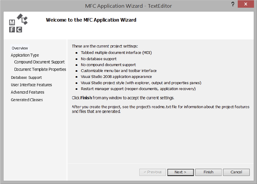
The dialog explains the project settings that are currently in effect, and in the left pane you have a range of options. You can choose any of these to have a look if you want — you can always get back to the base dialog by selecting the Overview option. Selecting any of the options on the left presents you with a range of further choices, so there are a lot of options in total. I won’t discuss all of them — I’ll just outline the ones that you are most likely to be interested in and leave you to investigate the others. Selecting Application Type enables you to choose from an SDI application, an MDI application that optionally can be tabbed, a dialog-based application, or an application with multiple top-level documents. Let’s create an SDI application first and explore what some of the choices are.
Creating an SDI Application
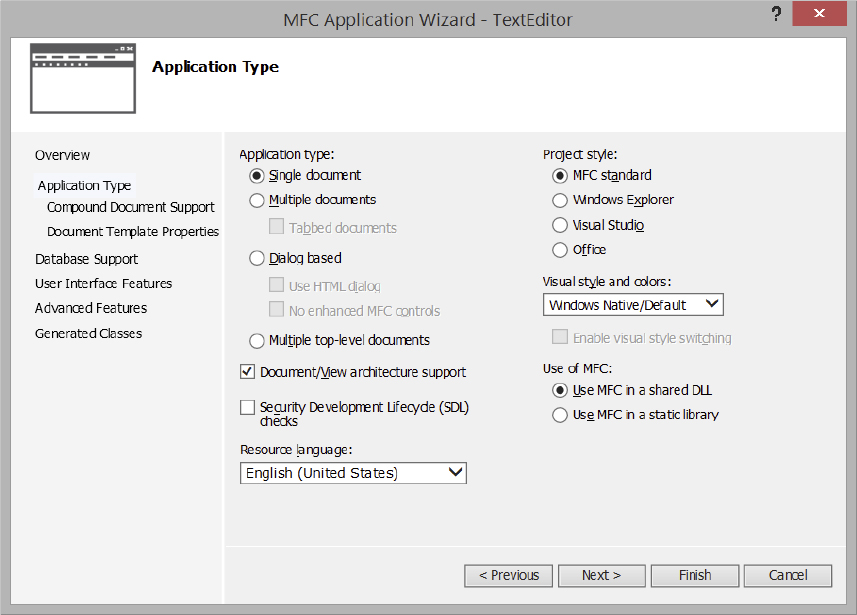
Select the Application Type option from the list in the left dialog pane. The default option selected is Multiple documents with the tabbed option, which selects the MDI with each document in its own tabbed page; the appearance of this is shown at the top left in the dialog so that you’ll know what to expect. Select the Single document Application type option, the MFC standard Project style option, and the Windows Native/Default option from the drop-down list of visual styles. The representation for the application that is shown top-left changes to a single window, as shown in Figure 12-5.
Some of the other options you have for the application type are:
| OPTION | DESCRIPTION |
|---|---|
| Dialog based | The application window is a dialog window rather than a frame window. |
| Multiple top-level documents | Documents are displayed in child windows of the desktop rather than child windows of the application as they are with an MDI application. |
| Document/View architecture support | This option is selected by default so you get code built in to support the document/view architecture. If you uncheck this option, the support is not provided and it’s up to you to implement whatever you want. |
| Resource language | The list box displays the choices available that apply to resources such as menus and text strings. |
| Project style | Here you can choose the visual appearance of the application window. Your choice will depend on the environment in which you want to run the application and the kind of application. For example, you would select the Office option for a Microsoft Office–related application. |
If you hover the mouse cursor over any of the options, a tooltip will be displayed explaining the option.
You have several options for the Project style. I’ll select the MFC Standard option and suggest that you do the same. I also selected Windows Native/Default from the Visual style and colors drop-down list. This makes the application appearance the same as your current operating system.
You can also choose how the MFC library is used in your project. The default choice of using the MFC library as a shared DLL (Dynamic Link Library) means that your program links to MFC routines at run time. This reduces the size of the executable file that you’ll generate, but requires the MFC DLL to be on the machine that’s running it. Your application’s .exe module and the MFC .dll together may be bigger than if you statically link the MFC library. If you opt for static linking, the MFC library routines are included in the executable module for your program when it is built. If you keep the default option, several programs running simultaneously using the dynamic link library can all share a single copy of the library in memory.
If you select Document Template Properties in the left pane of the dialog, you can enter a file extension for files that the program creates in the right pane. The extension txt is a good choice for this example. You can also enter a Filter Name, which is the name of the filter that will appear in Open and Save As dialogs to filter the file list so only files with your file extension are displayed.
If you select User Interface Features from the list in the left pane, you get a further set of options that can be included in your application:
| OPTION | DESCRIPTION |
|---|---|
| Thick Frame | Enables you to resize the application window by dragging a border. It is selected by default. |
| Minimize box | This is also selected by default and provides a minimize box at the top right of the application window. |
| Maximize box | This option is also selected by default and provides a maximize box at the top right of the application window. |
| Minimized | If you select this option, the application starts with the window minimized so it appears as an icon. |
| Maximized | With this option selected, the application starts with the window maximized. |
| System Menu | This provides the main application window with a control-menu box in the title bar. |
| About box | This provides your application with an About dialog. |
| Initial status bar | This adds a status bar at the bottom of the application window containing indicators for CAPS LOCK, NUM LOCK, and SCROLL LOCK and a message line that displays help strings for menus and toolbar buttons. It also adds menu commands to hide or show the status bar. |
| Split window | This provides a splitter bar for each of the application’s main views. |
In the Command bars sub-options you can choose whether you use a classic Windows menu with a docking toolbar, an Internet Explorer style toolbar, a menu bar and toolbar that you can customize at run time, or a ribbon. The User-defined toolbars and images sub-option allows the toolbar and images to be customized at run time. The Personalized menu behavior sub-option enables menus to display only the items used most frequently. You would typically use a ribbon with applications that complement Microsoft Office. In this example, we will use the classic menu with a classic docking toolbar.
You should be aware of a couple of features under the Advanced Features set of options. One is Printing and print preview, which is selected by default, and the other is the number of files on the recent file list. You can increase the latter to whatever you think is useful for the application. Printing and print preview add the standard Page Setup, Print Preview, and Print items to the File menu, and the Application Wizard also provides code to support these functions. You can uncheck all the other options for the example.
The Generated Classes option in the left pane of the dialog displays a list of the classes that will be generated, as shown in Figure 12-6.
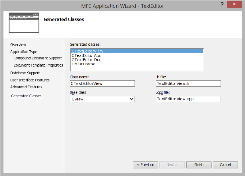
You can highlight any class in the list by clicking it, and the boxes below show the class name, the header filename in which the class definition will be stored, the base class, and the name of the source file containing the implementation of the class. The class definition is always in an .h file, and the member function definitions are always in a .cpp file.
You can alter everything except the base class for the CTextEditorDoc class. The only thing you can change for CTextEditorApp is the class name. Try clicking the other classes in the list. For CMainFrame, you can alter everything except the base class, and for the CTextEditorView class shown in Figure 12-6, you can change the base class as well. Click the down arrow to display the list of other classes that you can have as a base class. The capability built into your view class depends on which base class you select:
| BASE CLASS | VIEW CLASS CAPABILITY |
|---|---|
CEditView |
Provides simple multiline text-editing capability, including find and replace, and printing. |
CFormView |
Provides a view that is a form; a form is a dialog that can contain controls for displaying data and for input. |
CHtmlEditView |
Extends the CHtmlView class and adds the ability to edit HTML pages. |
CHtmlView |
Provides a view in which web pages and local HTML documents can be displayed. |
CListView |
Enables you to use the document-view architecture with list controls. |
CRichEditView |
Provides the capability to display and edit documents containing rich edit text. |
CScrollView |
Provides a view that automatically adds scrollbars when the data that is displayed requires them. |
CTreeView |
Provides the capability to use the document-view architecture with tree controls. |
CView |
Provides the basic capability for viewing a document. |
Because you’ve called the application TextEditor, with the notion that it is able to edit text, choose CEditView to get basic text editing. You can now click Finish to generate the program files for a fully working base program using the options you’ve chosen. This will take a little while.
MFC Application Wizard Output
All the program files generated by the Application Wizard are stored in the TextEditor project folder, which is a subfolder to the solution folder with the same name. There are resource files in the res subfolder to the project folder. The IDE provides several ways for you to view the information relating to your project:
| TAB/PANE | CONTENTS |
|---|---|
| Solution Explorer | Shows the files included in your project. The files are categorized in virtual folders with the names Header Files, Resource Files, and Source Files. |
| Class View | Displays the classes in your project and their members and any global entities. The classes are shown in the upper pane, and the lower pane displays the members for the class selected in the upper pane. By right-clicking entities in Class View, you can display a menu that you can use to view the definition of the entity or where it is referenced. |
| Resource View | Displays resources such as menu items and toolbar buttons used by your project. Right-clicking a resource displays a menu for editing the resource or adding new resources. |
| Property Manager | Displays the versions you can build for your project. The debug version includes extra facilities to make debugging easier. The release version results in a smaller executable, and you build this version when your code is fully tested. By right-clicking a version you can display a context menu where you can add a property sheet or display the properties currently set for that version. A property sheet enables you to set options for the compiler and linker. |
You can switch to view any of these by selecting from the View menu or clicking on a tab label. If you right-click TextEditor in the Solution Explorer pane and select Properties from the pop-up, the project properties window is displayed, as shown in Figure 12-7.
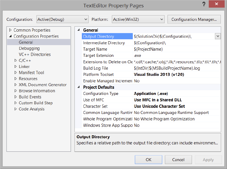
The left pane shows the property groups you can select to be displayed in the right pane. Currently, the General group of properties is displayed. You can change the value for a property in the right pane by clicking it and selecting a new value from the drop-down list box to the right of the property name or, in some cases, by entering a new value.
At the top of the property pages window, you can see the current project configuration and the target platform when the project is built. You can change these by selecting from the drop-down list for each. By selecting All Configurations you can change properties for both the Debug and Release configurations.
Viewing Project Files
The left pane in the IDE can display several tabs. The most useful are the Solution Explorer, Class View, and Resource View tabs. You can hide the currently visible tab by clicking the down arrow in the top right of the pane and selecting Hide from the menu. I’ll just show the three interesting tabs in figures. I’ll also show the pane as an undocked window, which you get by dragging its title bar away from the edge of the main window.
If you select the Solution Explorer tab and expand the list by clicking the arrow symbol for TextEditor files and then click the arrow symbol for each of the Source Files, Header Files, and Resource Files folders, you’ll see the complete list of files for the project, as shown in Figure 12-8. To collapse any expanded branch of the tree, just click the arrow symbol.
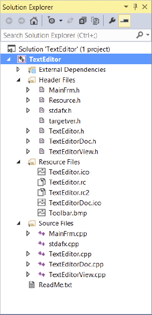
There are a total of 18 files shown in the project, excluding ReadMe.txt. You can view the contents of any file by double-clicking the filename. The contents of the file selected are displayed in the Editor window. Try it out with the ReadMe.txt file. You’ll see that it contains a brief explanation of the contents of each of the files that make up the project. I won’t repeat the descriptions of the files here, because they are very clearly summarized in ReadMe.txt.
Viewing Classes
The Class View tab is often more convenient than the Solution Explorer tab because classes are the basis for the organization of the application. When you want to look at the code, it’s typically a class definition or the implementation of a member function you want, and from Class View you can go directly to either. The Solution Explorer pane comes in handy when you want to check the #include directives in a .cpp file. From Solution Explorer you can open the file you’re interested in directly.
In the Class View pane, you can expand the TextEditor classes item to show the classes defined for the application. Clicking the name of any class shows the members of that class in the lower pane. In the Class View pane shown in Figure 12-9, the CTextEditorDoc class has been selected.

The icons characterize the things that are displayed. You will find a key to what the icons indicate in the Class View documentation. Search for “Class View and Object Browser Icons.” You can see that you have the four classes that I discussed earlier that are fundamental to an MFC application: CTextEditorApp for the application, CMainFrame for the application frame window, CTextEditorDoc for the document, and CTextEditorView for the view. You also have a CAboutDlg class that defines objects that support the dialog box that appears when you select the menu item Help ![]() About in the application. If you select Global Functions and Variables, you’ll see that it contains three items, as in Figure 12-10.
About in the application. If you select Global Functions and Variables, you’ll see that it contains three items, as in Figure 12-10.
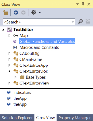
The application object, theApp, appears twice because there is an extern statement for theApp in TextEditor.h and a definition for it in TextEditor.cpp. If you double-click either of the appearances of theApp, it will take you to the corresponding statement. indicators is an array of four IDs for items that appear in the status bar: a separator, caps lock status, num lock status, and scroll lock status.
To view the code for a class definition double-click the class name in Class View. Similarly, to view the code for a member function, double-click the function name. Note that you can drag the edges of any of the panes in an IDE window to view its contents or your code more easily. You can hide or show the set of panes by clicking the close button at the right end of the pane title bar.
The Class Definitions
I won’t go into the application classes in complete detail here — you’ll just get a feel for how they look and I’ll highlight a few important aspects. The precise content of each class that is generated depends on the options you select when creating the project. If you double-click the name of a class in the Class View, the code defining the class is displayed.
The Application Class
Take a look at the application class, CTextEditorApp, first. The definition for this class is shown here:
// TextEditor.h : main header file for the TextEditor application
//
#pragma once

#ifndef __AFXWIN_H__
  #error "include 'stdafx.h' before including this file for PCH"
#endif

#include "resource.h"       // main symbols


// CTextEditorApp:
// See TextEditor.cpp for the implementation of this class
//

class CTextEditorApp : public CWinApp
{
public:
  CTextEditorApp();


// Overrides
public:
  virtual BOOL InitInstance();

// Implementation
  afx_msg void OnAppAbout();
  DECLARE_MESSAGE_MAP()
};

extern CTextEditorApp theApp;
The CTextEditorApp class derives from CWinApp and includes a constructor, a virtual function InitInstance(), a function OnAppAbout(), and a macro DECLARE_MESSAGE_MAP().
The DECLARE_MESSAGE_MAP() macro defines which Windows messages are handled by which member functions of the class. The macro appears in the definition of any class that can process Windows messages. Of course, our application class inherits a lot of functions and data members from the base class, and you will be looking further into these as you expand the program examples. If you look at the beginning of the code for the class definition, you will notice that the #pragma once directive prevents the file being included more than once. Following that is a group of preprocessor directives that ensure that the stdafx.h file is included before this file.
The Frame Window Class
The application frame window for our SDI program is created by an object of the class CMainFrame, which is defined by the following code:
// MainFrm.h : interface of the CMainFrame class
//

#pragma once

class CMainFrame : public CFrameWnd
{

protected: // create from serialization only
  CMainFrame();
  DECLARE_DYNCREATE(CMainFrame)

// Attributes
public:

// Operations
public:

// Overrides
public:
  virtual BOOL PreCreateWindow(CREATESTRUCT& cs);

// Implementation
public:
  virtual ~CMainFrame();
#ifdef _DEBUG
  virtual void AssertValid() const;
  virtual void Dump(CDumpContext& dc) const;
#endif

protected:  // control bar embedded members
  CToolBar          m_wndToolBar;
  CStatusBar        m_wndStatusBar;

// Generated message map functions
protected:
  afx_msg int OnCreate(LPCREATESTRUCT lpCreateStruct);
  DECLARE_MESSAGE_MAP()

};
This class is derived from CFrameWnd, which provides most of the functionality required for our application frame window. The derived class includes two protected data members — m_wndToolBar, and m_ wndStatusBar, which are instances of the MFC classes CToolBar, and CStatusBar, respectively. The toolbar provides buttons to access standard menu functions, and the status bar appears at the bottom of the application window.
The Document Class
The definition of the CTextEditorDoc class that was created is:
// TextEditorDoc.h : interface of the CTextEditorDoc class
//


#pragma once


class CTextEditorDoc : public CDocument
{
protected: // create from serialization only
  CTextEditorDoc();
  DECLARE_DYNCREATE(CTextEditorDoc)

// Attributes
public:

// Operations
public:

// Overrides
public:
  virtual BOOL OnNewDocument();
  virtual void Serialize(CArchive& ar);
#ifdef SHARED_HANDLERS
  virtual void InitializeSearchContent();
  virtual void OnDrawThumbnail(CDC& dc, LPRECT lprcBounds);
#endif // SHARED_HANDLERS

// Implementation
public:
  virtual ~CTextEditorDoc();
#ifdef _DEBUG
  virtual void AssertValid() const;
  virtual void Dump(CDumpContext& dc) const;
#endif

protected:

// Generated message map functions
protected:
  DECLARE_MESSAGE_MAP()

#ifdef SHARED_HANDLERS
  // Helper function that sets search content for a Search Handler
  void SetSearchContent(const CString& value);
#endif // SHARED_HANDLERS

#ifdef SHARED_HANDLERS
private:
  CString m_strSearchContent;
  CString m_strThumbnailContent;
#endif // SHARED_HANDLERS
};
Most of the meat comes from the base class and is therefore not apparent here. The DECLARE_DYNCREATE() macro that appears after the constructor (and was also used in CMainFrame) enables an object of the class to be created dynamically by synthesizing it from data from a file. When you save an SDI document object, the frame window that contains the view is saved along with your data. This allows everything to be restored when you read it back. Reading and writing a document object to a file is supported by a process called serialization. You will see how to serialize your own documents and then read them back in the examples we will develop.
The document class also includes the DECLARE_MESSAGE_MAP() macro to enable Windows messages to be handled by class member functions.
The View Class
The view class in our SDI application is defined as:
// TextEditorView.h : interface of the CTextEditorView class
//

#pragma once


class CTextEditorView : public CEditView
{
protected: // create from serialization only
  CTextEditorView();
  DECLARE_DYNCREATE(CTextEditorView)

// Attributes
public:
  CTextEditorDoc* GetDocument() const;

// Operations
public:

// Overrides
public:
  virtual BOOL PreCreateWindow(CREATESTRUCT& cs);
protected:
  virtual BOOL OnPreparePrinting(CPrintInfo* pInfo);
  virtual void OnBeginPrinting(CDC* pDC, CPrintInfo* pInfo);
  virtual void OnEndPrinting(CDC* pDC, CPrintInfo* pInfo);

// Implementation
public:
  virtual ~CTextEditorView();
#ifdef _DEBUG
  virtual void AssertValid() const;
  virtual void Dump(CDumpContext& dc) const;
#endif

protected:

// Generated message map functions
protected:
  DECLARE_MESSAGE_MAP()
};

#ifndef _DEBUG  // debug version in TextEditorView.cpp
inline CTextEditorDoc* CTextEditorView::GetDocument() const
   { return reinterpret_cast<CTextEditorDoc*>(m_pDocument); }
#endif
As you specified in the Application Wizard dialog, the view class is derived from CEditView, which already includes basic text handling facilities. The GetDocument() function returns a pointer to the document object corresponding to the view, and you use this to access data in the document object when you add your own extensions to the view class that allow user interactions to add to or modify the document data.
There are two implementations for the GetDocument() member of the CTextEditorView class in the code generated by Application Wizard. The one in the .cpp file is used for the debug version of the program. You will normally use this during program development because it provides validation of the pointer value stored for the document. (This is stored in the inherited data member m_pDocument in the view class.) The version that applies to the release version of your program you can find after the class definition in TextEditorView.h. This version is declared as inline and it does not validate the document pointer. The GetDocument() function provides the view object with access to the document object. You can call any of the functions in the interface to the document class using the pointer to the document that the function returns.
By default, you have debug capability included. As well as the special version of GetDocument(), there are lots of checks in the MFC code that are included in this case. If you want to change this, you can use the drop-down list box in the Build toolbar to choose the release configuration, which doesn’t contain the debug code.
Creating an Executable Module
To compile and link the program, you can click Build ![]() Build Solution, or press F7, or click the Build icon in the toolbar.
Build Solution, or press F7, or click the Build icon in the toolbar.
The first time you compile and link a program, it will take some time. The second and subsequent times should be quite a bit faster because of precompiled headers. During the initial compilation, the compiler saves the output from compiling header files included in stdafx.cpp. in a file with the extension .pch. On subsequent builds, if the source in a header has not changed, the compiler will skip compiling the header and use the precompiled code, thus saving the compilation time for the header.
You can determine whether or not precompiled headers are used and control how they are handled through the Properties dialog. Right-click TextEditor in Class View and select Properties from the menu. If you expand the C/C++ node, you can select Precompiled Headers to set or unset this property.
Running the Program
To execute the program, press Ctrl+F5. Because you chose CEditView as the base class for the CTextEditorView class, the program is a fully functioning, simple text editor. You can enter text in the window, as shown in Figure 12-11.
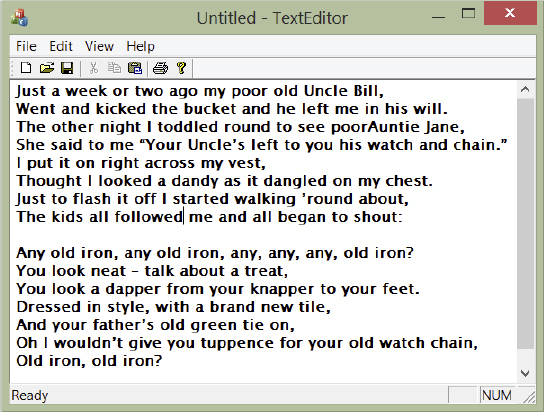
Note that the application has scroll bars for viewing text outside the visible area within the window, and, of course, you can resize the window by dragging the boundaries. All the items under all menus are fully operational so you can save and retrieve files, you can cut and paste text, and you can print the text in the window — and all that without writing a single line of code! As you move the cursor over the toolbar buttons or the menu options, prompts appear in the status bar describing their functions, and if you let the cursor linger on a toolbar button, a tooltip is displayed showing its purpose. (You’ll learn about tooltips in more detail in Chapter 13.)
How the Program Works
The application object is created at global scope. You can see this if you expand Global Functions and Variables in Class View and double-click the second theApp. In the Editor window, you’ll see this statement:
CTextEditorApp theApp;This declares theApp as an instance of our application class CTextEditorApp. The statement is in TextEditor.cpp, which also contains member function definitions for the application class, and the definition of the CAboutDlg class.
After theApp has been created, the MFC-supplied WinMain() function is called. This calls two member functions of the theApp object. First, it calls InitInstance(), which provides any initialization of the application that is necessary, and then the Run()function that is inherited from CWinApp, which provides initial handling for Windows messages. If you want to see the code for CWinApp functions, extend the tree for CTextEditorApp in Class View and extend Base Types. You can then click on CWinApp to see the members in the lower pane. WinMain() does not appear explicitly in the project source code, because it is supplied by the MFC class library and is called automatically when the application starts.
The InitInstance() Function
You can access the code for the InitInstance() function by double-clicking its entry in Class View after highlighting CTextEditorApp — or, if you’re in a hurry, you can just look at the code immediately following the line defining the theApp object. There’s a lot of code in the version created by the Application Wizard, so I just want to remark on a couple of fragments in this function. The first is:
  SetRegistryKey(_T("Local AppWizard-Generated Applications"));
  LoadStdProfileSettings(4);  // Load standard INI file options (including MRU)
The string passed to the SetRegistryKey() function defines a registry key under which program information is stored. You can change this to whatever you want. If I changed the argument to "Horton", information about our program would be stored under the registry key:
HKEY_CURRENT_USERSoftwareHortonTextEditorAll the application settings are stored under this key, including the most recently used files list. The call to LoadStdProfileSettings() loads the application settings that were saved last time around. Of course, the first time you run the program, there aren’t any.
A document template object is created dynamically within InitInstance() by the statement:
pDocTemplate = new CSingleDocTemplate(
    IDR_MAINFRAME,
    RUNTIME_CLASS(CTextEditorDoc),
    RUNTIME_CLASS(CMainFrame),       // main SDI frame window
    RUNTIME_CLASS(CTextEditorView));
The first parameter to the CSingleDocTemplate constructor is a symbol, IDR_MAINFRAME, which defines the menu and toolbar to be used with the document type. The following three parameters define the document, the mainframe window, and the View Class objects that are to be bound together within the document template. Because you have an SDI application here, there is only one of each in the program, managed through one document template object. RUNTIME_CLASS() is a macro that enables the type of a class object to be determined at run time.
There’s a lot of other stuff here for setting up the application instance that you need not worry about. You can add any initialization of your own that you need for the application to the InitInstance() function.
The Run() Function
The CTextEditorApp class inherits the Run() function from CWinApp. Because the function is declared as virtual, you could replace the inherited version with your own, but this is not usually necessary. Run() receives all the messages from Windows destined for the application and ensures that each message is passed to the function designated to service it, if one exists. Therefore, this function continues executing as long as the application runs.
You can boil the operation of the application down to four steps:
- Creating an application object,
theApp. - Executing
WinMain(), which is supplied by MFC. WinMain()callingInitInstance(), which creates the document template, the mainframe window, the document, and the view.WinMain()callingRun(), which executes the main message loop to acquire and dispatch Windows messages.
Creating an MDI Application
Now let’s create an MDI application using the MFC Application Wizard. Press Ctrl+Shift+N and give the project the name Sketcher — and plan on keeping it. You’ll be expanding this into a sketching program during subsequent chapters. You should have no trouble with this procedure, because there are only a few things that you need to do differently from creating the SDI application.
- For the Application Type group of options:
- Leave the default option, Multiple documents, but opt out of Tabbed documents.
- Keep Document/View architecture support.
- Select MFC standard as the project style and Windows Native/Default as the Visual style and colors option.
- Compound Document Support options should be the default selection,
None. - For the Document Template Properties set of options in the dialog:
- Specify the file extension as
ske. You’ll see that you automatically get a filter for*.skedocuments defined. - Change the
Doctype name toSketch. - Change the
File newshort name toSketch.
- Specify the file extension as
- Leave the Database Support options at the default settings,
None. - For the User Interface Features options:
- Keep Use a classic menu, and the sub-option, Use a classic docking toolbar.
- Keep the other options that are selected by default: Thick frame, Minimize box, Maximize box, System menu, Initial status bar, Child minimize box and Child maximize box.
- For the Advanced features set of options:
- Keep the Printing and print preview option.
- Deselect ActiveX controls, and Support Restart Manager.
- Leave the Generated Classes options at the default settings so the base class for the
CSketcherViewclass isCView.
You can see in the dialog with Generated Classes selected that you get an extra class for your application compared with the TextEditor example, the CChildFrame class, which is derived from CMDIChildWnd. This class provides a frame window for a view of the document that appears inside the application window created by a CMainFrame object. With an SDI application, there is a single document with a single view, so the view is displayed in the client area of the mainframe window. In an MDI application, you can have multiple documents open, and each document can have multiple views. To provide for this, each document view has its own child frame window created by a CChildFrame object. As you saw earlier, a view is displayed in a separate window, but one which exactly fills the client area of a frame window. Finally, click Finish to generate the project.
Running the Program
You can build and run the program by pressing Ctrl+F5. You get the application window shown in Figure 12-12.
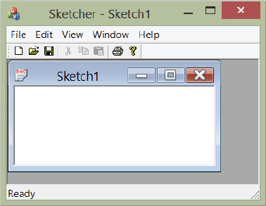
In addition to the main application window, you have a separate document window with the caption Sketch1. Sketch1 is the default name for the initial document, and it has the extension.ske if you save it. You can create additional views for the document by selecting the Window ![]() New Window menu option. You can also create a new document by selecting File
New Window menu option. You can also create a new document by selecting File ![]() New, so that there will be two active documents in the application. The situation with two views open for a document, is shown in Figure 12-13.
New, so that there will be two active documents in the application. The situation with two views open for a document, is shown in Figure 12-13.
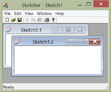
You can expand either sketch window to fill the client area. You can then switch between the sketch windows through the Window drop-down menu. You can’t yet actually create any data in the application because we haven’t added any code to do that, but all the code for creating documents and views has already been included by the Application Wizard.
SUMMARY
In this chapter, you’ve been concerned with the mechanics of using the MFC Application Wizard. You have seen the basic components of the MFC programs that the Application Wizard generates for both SDI and MDI applications. All our MFC examples are created by the MFC Application Wizard, so it’s a good idea to keep the general structure and broad class relationships in mind. You probably won’t feel comfortable with the details at this point, but don’t worry about that. You’ll find it becomes much clearer after you begin developing applications in the succeeding chapters.
EXERCISES
It isn’t possible to give programming examples for this chapter, because it really just introduced the basic mechanics of creating MFC applications. There aren’t solutions to all the exercises because you will either see the answer for yourself on the screen, or be able to check your answer with the text.
- What is the relationship between a document and a view?
- What is the purpose of the document template in an MFC Windows program?
- Why do you need to be careful, and plan your program structure in advance, when using the Application Wizard?
- Code up the simple text editor program. Build both debug and release versions, and examine the types and sizes of the files produced in each case.
- Generate the text editor application several times, trying different project styles from the Application Type in Application Wizard.
WHAT YOU LEARNED IN THIS CHAPTER
| TOPIC | CONCEPT |
|---|---|
| The Application Wizard | The MFC Application Wizard generates a complete, working, framework Windows application for you to customize to your requirements. |
| SDI and MDI programs | The Application Wizard can generate single-document interface (SDI) applications that work with a single document and a single view, or multiple-document interface (MDI) programs that can handle multiple documents with multiple views simultaneously. |
| Classes in SDI programs | The four essential classes in an SDI application that are derived from the foundation classes are the application class, the frame window class, the document class, and the view class. |
| The application object | A program can have only one application object. This is defined automatically by the Application Wizard at global scope. |
| Document objects | A document class object stores application-specific data, and a view class object displays the contents of a document object. |
| Document templates | A document template class object is used to tie together a document, a view, and a window. For an SDI application, a CSingleDocTemplate class does this, and for an MDI application, the CMultiDocTemplate class is used. These are both foundation classes, and application-specific versions do not normally need to be derived. |