Chapter 6. Animating Characters and 3D Layers
Chapter Objectives
Chapter Learning Objectives
 Use puppet animation techniques.
- Use 3D layers.
- Animate a layer in 3D space.
- Use views and animate cameras.
- Animate text along a path from Adobe Illustrator.
Chapter ACA Objectives
For more information on ACA Objectives, see pages 294–299.
DOMAIN 2.0 Project Setup and Interface
2.1, 2.2
DOMAIN 4.0 Creating and Modifying Visual Elements
4.1, 4.2, 4.5, 4.6, 4.7
So far, you’ve worked with Adobe After Effects CC layers in two dimensions, as if they were photo prints and pieces of paper. After Effects also lets you work with layers in 3D space so that you can arrange layers at different distances and spin them like a top, which you’ll do in this chapter (Figure 6.1).

Figure 6.1 One of the videos you’ll create in this chapter
To keep things simple, 3D features are turned off by default. When you’re ready to use them, you just turn them on, as you’ll do in this chapter.
![]() ACA Objective 2.1
ACA Objective 2.1
![]() ACA Objective 4.6
ACA Objective 4.6
Starting the Ad Project
In this chapter, you’ll create an ad for Hot Digity Dog treats using 3D features and some animated credits with the help of a path from Adobe Illustrator.
![]() Video 6.1
Video 6.1
Starting the Ad Project
All of the files needed to create the animations are available in the Chapter 6 lesson folder. They’re a mix of videos and still image files.
To get started:
Tip
When you start After Effects and close the Start screen, you’re already looking at a blank new project. All you have to do is save it
Create a new project. Save the new project with the name Treats in the Chapter 6 lesson folder.
On the desktop, select all the files in the lesson folder except treats.aep.
Import all the selected files into the Project panel in After Effects.
Remember to keep your files organized as you build this project. You can start by moving the three video files into their own folder in the Project panel (you can name the folder Media), as in previous lessons. Also, create another folder at the top level of the Project panel and name it Comps.
Creating the Ad Composition
You have a project; now you need a composition before you can start animating.
To start the ad composition:
In the Project panel, select the Comps folder so the new composition will be created there.
Press Ctrl+N (Windows) or Command+N (macOS), the keyboard shortcut for the Composition > New Composition command, and do the following:
 Name the new composition Treats Comp.
- From the Preset menu in the Composition Settings dialog box, choose the HDTV 1080 29.97 preset.
- Set the Duration for 5 seconds.
Click OK.
Creating a Wall Graphic
The first layer you’ll need in this composition is a graphic of a back wall, which you will create using a solid layer with a gradient effect applied to it.
To create the solid:
Press Ctrl+Y (Windows) or Command+Y (macOS), the keyboard shortcut for the Layer > New Layer command, and do the following:
- Name it Wall.
- Give it a width of 1920 pixels and a height of 700 pixels. The height is shorter than the composition height of 1080 pixels because it doesn’t need to cover the entire composition.
- Choose a color that doesn’t match the composition background color. The exact color doesn’t matter because it will soon be replaced by an effect.
Click OK.
Move the solid so that its top meets the top of the composition frame. You can do this using any method you’ve learned so far, such as:
- Nudging it using the arrow keys (add the Shift key to move 10 pixels at a time).
- Editing its Position property.
- Using the Align panel to align the top of the solid with the top of the composition.
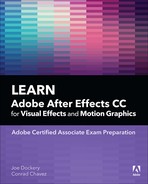
To set the appearance of the Wall layer, you’ll now apply a gradient to it (Figure 6.2).
In the Effects & Presets panel, find the Gradient Ramp effect and apply it to the solid.
In the Effect Controls panel, edit the Start Color and End Color properties of the Gradient Ramp effect:
- Set Start Color to red; Video 6.1 uses a hexadecimal color value of D80000.
- Set End Color to black. The hex color value for black is 000000.
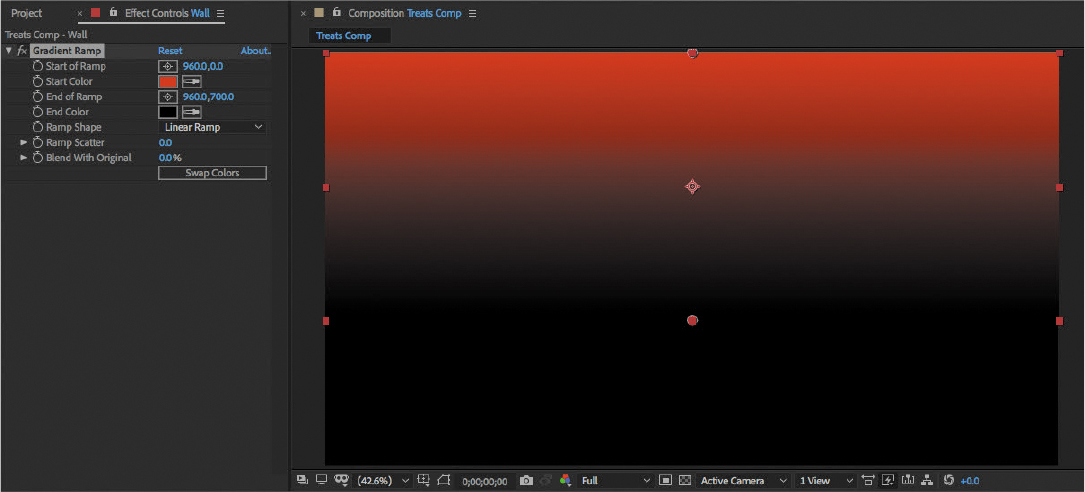
Figure 6.2 Wall solid in position with Gradient Ramp effect applied
Creating a Floor Graphic
The Wall solid was given a height of only 700 pixels because a floor graphic would occupy the bottom of the composition frame.
To add the floor, add floor.jpg to the composition. Scale and position it so that
- Its width matches the composition width.
- Its top edge meets the bottom edge of the Wall layer.
- Click the Toggle Transparency Grid button (
 ) can help you see if there’s a gap between the wall and floor.
Tip
Remember that you can make a layer match the width of a composition by choosing Layer > Transform > Fit To Comp Width.
It would be nice to make the floor lighting more consistent with the wall. The same type of shading can be added by layering another solid on top of the wall with a similar gradient (Figure 6.3):
Drag the Wall solid from the Solids folder in the Project window into the composition to create a second instance of it.
Position the solid so that its top edge meets the top edge of the floor.jpg layer. You’ll no longer be able to see the floor.jpg layer, but this is just temporary.
Rename the layer Floor Shadow.
As you did earlier, apply the Gradient Ramp effect to the second instance of the Wall solid, but this time, make it black on top and white on the bottom.
In the Timeline panel, choose Multiply from the Mode menu for the second Wall solid instance.
Tip
If you don’t see a Mode menu in the Timeline panel, click Toggle Switches/Modes at the bottom of the Timeline panel.
The effect is too strong, so an easy way to dial it back is to lower the layer’s Opacity value.
Change the opacity of the Floor Shadow layer to 70 percent. (Remember that this involves revealing and then editing the Opacity property of the Floor Shadow layer.)
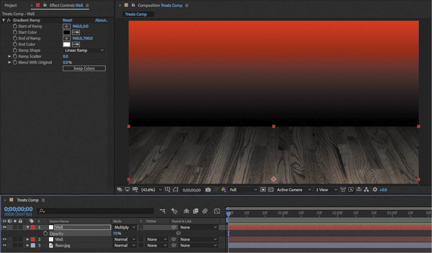
Figure 6.3 Background graphics complete
Pre-composing the Background
Tip
A quick way to select everything is to press Ctrl+A (Windows) or Command+A (macOS), the keyboard shortcut for the Select All command
To simplify the composition before adding more elements, it’s a good idea to pre-compose the layers created so far into their own nested composition.
To pre-compose the layers:
Select all of the layers created so far.
Choose Layer > Pre-compose.
In the Pre-compose dialog box, enter a New Composition Name of Background, and click OK.
![]() ACA Objective 4.1
ACA Objective 4.1
Adding the Ad Elements
![]() Video 6.2
Video 6.2
Adding the Ad Elements
The animated ad you’re creating will ultimately have a graphic of a dog and the name of the product. It’s time to add both.
First, bring the dog graphic into the composition:
Add Puppy-puppet.png to the composition.
You might notice that the graphic has a .PNG filename extension. It’s a Portable Network Graphics (PNG) file. A PNG file may have a larger file size than a JPEG version of the same file, but unlike a JPEG image, a PNG image can include transparency. You can see the transparency in use in the composition, because what you see behind the outline of the dog is the composition, not a blank image background.
Position and scale the dog on the floor in the right half of the composition frame, leaving room in the top left quarter of the frame.
Now add the text (Figure 6.4):
With the Horizontal Type tool, create a new text layer containing the words Hot Digity Dog Treats.
Use the Character panel to format the text layer using any type specifications you like, as long as its general appearance, size, and position are consistent with what’s shown in Video 6.2.
Rotate the type layer about –17 degrees. (Remember that you can do this using the Rotation tool, or by editing the Rotation property of the type layer.)
Figure 6.4 The text layer set up and in position. The font used is different than the one used in the video.
![]() ACA Objective 4.5
ACA Objective 4.5
Animating the Dog with Puppet Animation
![]() Video 6.3
Video 6.3
Animating the Dog with Puppet Animation
The visual interest of the Hot Digity Dog Treats ad will be created in part by an animated graphic of a dog. You’ve already got the dog in the composition, so now you just need to animate it.
In the concept for the dog animation, the dog’s tail wags and it bows down slightly on its front legs. This requires animating parts of the graphic. But so far in this book, you’ve used keyframes to animate an entire layer equally, which won’t achieve the goal. You might also remember that it’s possible to animate parts of a shape or mask path by keyframing individual points, but the dog graphic is a pixel-based image, not a vector path. You’ll need a different tool or technique to be able to animate the dog graphic’s tail and front legs independently.
Adding Puppet Animation Pins
The way you’ll animate the dog is using the Puppet animation tools. Puppet animation lets you lay down pins to mark points you want to control. This works great for animating graphics of people and animals; for example, to animate an arm you could set one pin at an elbow and another at the hand; dragging the hand pin swings the forearm at the elbow. Pins should be added to natural joints and other body parts that move. This helps the animation look more realistic.
To set Puppet animation pins (Figure 6.5):
In the Tools panel, select the Puppet Pin tool (
 ).The Puppet Pin tool is grouped with other Puppet tools, so if you don’t see it on the Tools panel, position the pointer over a Puppet tool and hold the mouse button down to reveal the other tools in its group.
Click the dog layer to add pins at locations you want to control. Puppet pins are yellow.
Click the Show button to display the distortion mesh. Notice how the mesh is based on both the pin locations and the detected edges of the graphic.

Figure 6.5 Pin locations on the dog mesh, as used in Video 6.3.
Understanding Puppet Animation
Puppet animation is based on both the pins you lay down and a distortion mesh that After Effects automatically creates based on your pin locations. Before you continue, it’s a good idea to gain some understanding of how the pins and mesh work.
To begin animating using the puppet pins, first drag the pin at the front paw. The dog’s arm pivots around the pin at its shoulder. You can also drag the pin at the tail to see how it would move. No animation has been created yet, but playing with the pins at this point does set the state of the animation at the current time.
When you use the Puppet Pin tool, the two other options in the Mesh options group adjust the automatically generated mesh (Figure 6.6):
- Expansion. Increasing Expansion can help when the current mesh doesn’t include some parts of the graphic that might extend from the main shape. As demonstrated in Video 6.3, when an expanded mesh has trouble distinguishing separate projecting elements, reducing Expansion can help.
- Density. Increasing Density creates a more complex mesh that uses more triangles. This can result in higher animation precision, but it requires more processing power and may take longer to render. It’s one of those cases where you want to find the right balance between precision and speed.

Figure 6.6 Mesh options in the Tools panel when the Puppet Pin tool is selected
Other Puppet Animation Tools
The Puppet tools group includes two other tools in addition to the Puppet Pin tool:
- Puppet Starch tool. Click the Puppet Starch tool on the mesh to prevent that point from being animated. Starch points “freeze” an area and appear in red.
- Puppet Overlap tool. When animating one part of the mesh over another, you may require a specific overlap order. For example, when moving a hand over a face by dragging a pin on the hand, you almost always want the hand to go in front of the face. If the hand goes behind the face, you can click the pin with the Puppet Overlap tool and then increase the In Front value on the Tools panel until the hand is in front of the face.
The Extent value on the Tools panel controls how far out the pin influences the grid. The In Front and Extent options appear only when the Puppet Overlap tool is selected.
For the Puppy-puppet.png layer, you probably don’t need to use the Puppet Overlap tool. But you may want to lock down parts of the dog using the Puppet Starch tool (Figure 6.7), as demonstrated in Video 6.3.
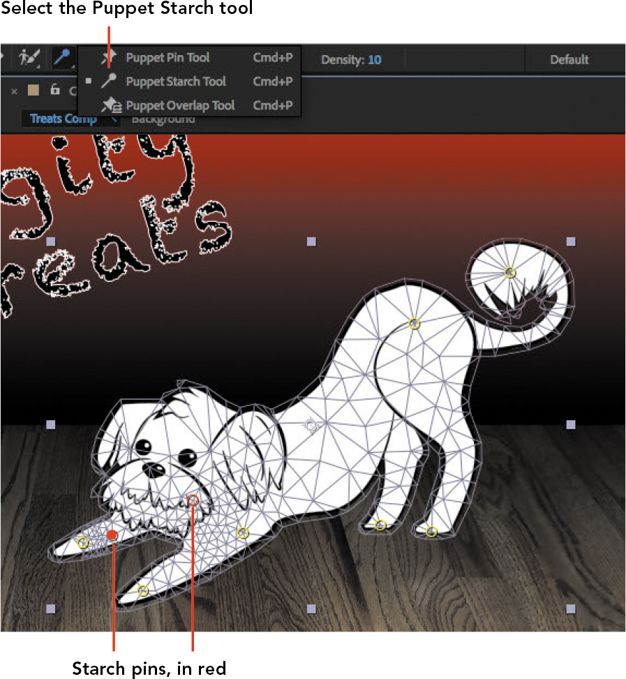
Figure 6.7 Starch pins on the dog
Recording Puppet Animation
You could animate the pins by adding keyframes and changing values, but that might be a tedious and time-consuming way to create lifelike animation. Fortunately, After Effects can record the animation you want in an easy, interactive way.
You’ll hold down a key, and as long as that key is held down, pin movements you drag are recorded in real time.
To record a puppet animation:
Make sure the layer you want to animate is selected and that you’ve added all the pins you want it to have.
Change the current time to the frame when you want the animation to start. Video 6.3 starts at 10 frames (00:10).
When you’re ready to begin, hold down the Ctrl key (Windows) or Command key (macOS), and drag any yellow pin.
When you’re done, release the Ctrl/Command key. Keyframes appear in the Timeline panel for that puppet pin (Figure 6.8).
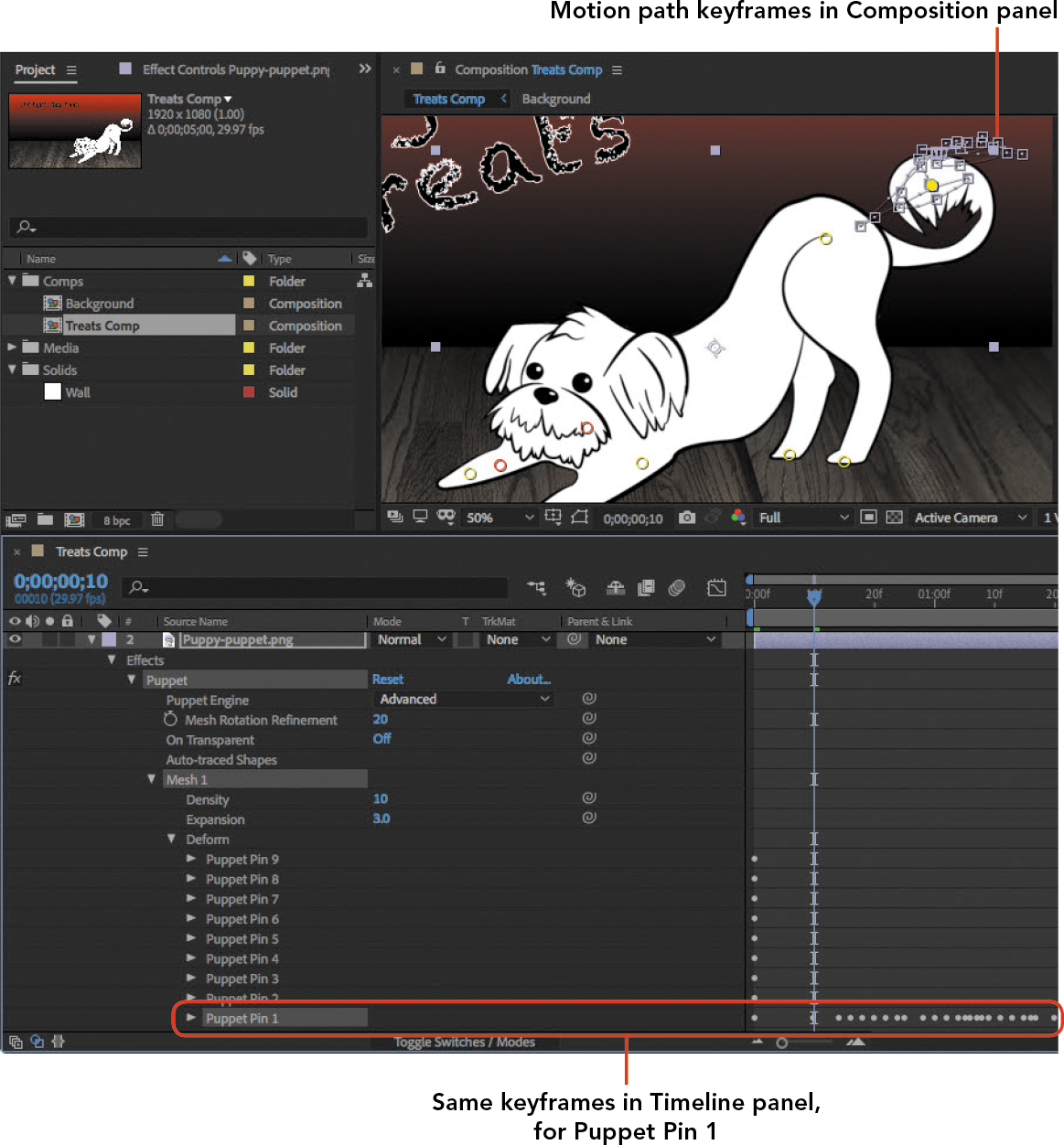
Figure 6.8 Keyframes automatically generated for a puppet pin property after recording animation
Keep the following in mind as you record puppet animation:
- As long as you hold down the Ctrl/Command key, After Effects records how you animate the pins. Recording stops when you release the Ctrl/Command key or at the end of the composition duration, whichever comes first.
- If you want to animate multiple pins over the same period, make multiple recording passes. Each pin has its own set of keyframes, so if you record the animation for a second pin, its keyframes appear on a separate puppet pin property for that mesh.
- You can name any pin in the Timeline panel so that you can label which part of the graphic that pin animates. You rename a pin the same way you’ve renamed layers and masks in the Timeline panel (press Enter or Return and type the new name).
- You can customize how puppet animation is recorded by clicking the Record Options text in the Tools panel when the Puppet Pin tool is selected.
Of course, if you want to edit any of the keyframe values, you can do so.
Creating a Custom Shape to Animate
![]() ACA Objective 4.5
ACA Objective 4.5
![]() Video 6.4
Video 6.4
Creating a Custom Shape to Animate
You’ll create a custom-colored shape as a backdrop for the Hot Digity Dog Treats text. It will be a free-form shape best drawn with the Pen tool. You used the Pen tool earlier in this book to draw paths and a mask. This time you’ll use it to draw a visible shape, and you’ll focus on drawing curves instead of straight segments.
You’ll create a simple closed shape similar to a rough ellipse, with a light green fill and a white stroke.
To create the shape:
In the Tools panel, select the Pen tool.
Set the fill and stroke in advance, in the Tools panel (Figure 6.9). You can approximate the colors demonstrated in Video 6.4; they don’t have to be exact.
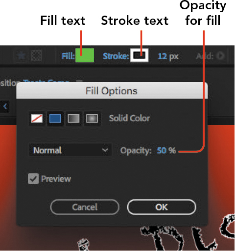
Figure 6.9 Setting up Fill and Stroke options for the shape you will draw
Note that the fill opacity is set to 50% in Video 6.4. This is only so that the text will show through and be used as a guide as the shape is drawn around it. Remember that Opacity for Fill or Stroke is set by clicking on the Fill or Stroke text in the Tools panel, not the color swatches.
Remember that with the Pen tool, you’re creating a path by laying down points. Clicking creates corner points, but this shape is intended to be rounded, so instead you’ll drag most or all of the points.
Make sure no layers are selected so that you create a shape layer instead of a layer mask.
Position the Pen tool slightly above and to the left of the first letter of the text (the H), then drag a short distance up and to the right. You’ll see control handles extend from the point; these shape the curve.
Position the Pen tool slightly above and to the right of the last letter of the first line, and drag a short distance down and to the right, shaping the resulting curve point before you release the mouse button.
Continue drawing the shape around the text by positioning and dragging the Pen tool to create curves. If you want one of the points to be a corner, that’s fine; click the Pen tool at that position rather than dragging.
When you’re ready to close the shape, position the Pen tool over the first point, and when you see a small circle below and to the right of the Pen tool pointer, click to close the path (Figure 6.10).

Figure 6.10 About to click the Pen tool to close the path, as indicated by the circle next to the bottom of the pointer
If you want to adjust the points, you can easily do so with the Selection tool or any of the Pen tools. For the details, review “Editing a Mask Path” in Chapter 5. Although this is a shape path and not a mask path, they’re both paths, so you edit them the same way.
If you lowered the Fill opacity of the shape, you can restore it to 100% at this time.
In the Timeline panel, drag Shape Layer 1 so it’s below the text layer, and rename it Green bg.
Rotating a Layer in 3D Space
![]() ACA Objective 4.6
ACA Objective 4.6
![]() Video 6.5
Video 6.5
Rotating a Layer in 3D Space
Now you’ll work with the text and shape layers in 3D space, opening up a whole new dimension of animation possibilities.
After Effects layers start out using 2D space. You can set any layer to be a 3D layer, which means it can use 3D space. This affects any property of that layer involving space. For example, instead of having only X and Y values in the Position property, a 3D layer has X, Y, and Z values; the Z value is depth.
In this composition you’ll rotate 3D layers in a way that is not possible for 2D layers.
To rotate a layer in 3D space:
Enable 3D space for a layer by clicking its 3D switch in the Timeline panel (Figure 6.11). For this exercise, enable the 3D switch for every layer.
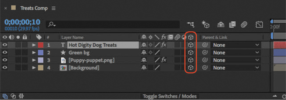
Figure 6.11 3D switches column in the Timeline panel
Tip
Keep in mind when doing other projects with 3D elements that some layers can be left in 2D space in a 3D project.
If you expand the properties for a 3D layer, you’ll see additional properties related to 3D.
Tip
If you don’t see the 3D switch column in the Timeline panel, click Toggle Switches/Modes at the bottom of the Timeline panel.
Select both the text layer and the Green bg layer and choose Layer > Transform > Center Anchor Point In Layer Content.
Because these two layers will be rotated together, making their anchor points consistent helps ensure that they will remain aligned during simultaneous rotation.
Note
The rotation of multiple layers may not be consistent, even if they use the same keyframe values, if their anchor points still have different position values. Video 6.5 demonstrates ways to align anchor points more precisely by using the Pan Behind (Anchor Point) tool.
In the Timeline panel, expand the Transform properties of the Green bg layer.
Change the current time to 00:05 (5 frames from the start).
Click the stopwatch for the Y Rotation layer to enable keyframe animation.
Change the current time to 01:00 (one second).
Change the Y Rotation value to 1x rotation (Figure 6.12).
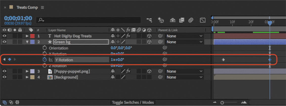
Figure 6.12 Setting up 3D rotation around the Y axis
Play back the animation to test it.
The layer is rotating around the Y axis so that its edges become closer and then farther from you as it rotates. This is not possible in 2D space, where there’s no depth.
To have the text layer perform the same rotation, simply choose the Green bg layer from the Parent & Link menu for the text layer (Figure 6.13).
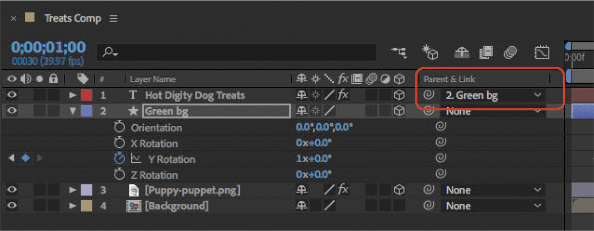
Figure 6.13 Parenting the text layer to the 3D rotation of the Green bg layer
This is a simple example of 3D rotation. If you play around with various 3D properties, you’ll find that you can animate 3D layers in many more ways. For example, you already know how to animate a 2D layer to make it move around the frame; you can fly a 3D layer so that it comes at you or zooms away from you. Of course, you can animate multiple 3D layers so that they move in multiple directions at once or chase each other around the frame.
Using 3D Camera Views
![]() ACA Objective 4.6
ACA Objective 4.6
![]() Video 6.6
Video 6.6
Using 3D Camera Views
A 3D composition isn’t just about layers; it’s also about point of view. One of the most important 3D objects is the camera, a type of layer that represents a point of view. A composition can have multiple cameras that look on a 3D composition from different angles.
A basic 3D composition has a single camera. You can also change the position of the camera to get the best view of the layers in 3D space. In addition, you can animate camera properties, such as its position, so that you can do things like fly the camera through the 3D composition. If you create a 3D composition of a city, you can fly the camera through the buildings. You can even create multiple cameras so that you can have multiple views of a 3D composition and cut between them.
Controlling the View of a Composition
You’ll find 3D view controls at the bottom of the Composition panel. The first control provides different views of the 3D composition, such as Top or Left. The second control provides single or multiple views in the Composition panel, such as showing two views laid out horizontally. You can then control what you see in each view.
If you’re using a regular computer monitor, which can show only two dimensions, these multiple views help visualize layer positions and movements in 3D space. For example, if you can’t see a layer where you expect it to be, looking at a different simultaneous view may show you that the layer is actually there but at an angle or distance that makes it hard to see from the first view you were looking at.
Video 6.6 demonstrates choosing the 2 Views option from the View Layout menu to show both the Top view and the view of the active camera (Figure 6.14). The Top view is useful for seeing how layers are positioned in Z space (depth).

Figure 6.14 Multiple views
The active view is the one with the blue corners. The View menu indicates how the active view is set.
Note
When you’re working in 2D space, a layer can hide another layer by being higher in the stacking order. In 3D space, a layer hides another layer when it’s closer in Z space.
Adding Cameras
If you want a composition to be seen from more than one viewpoint, you can add another camera to a composition. Because a camera is a layer, it’s got properties of its own. Some are properties you’ve already used, such as Position.
But a camera also has photographic camera properties. You can set its focal length and film (sensor) size, and even enable depth of field viewing. In other words, it simulates a photographic or cinema camera. You could even have two cameras in the same position with different focal lengths so that you can simulate a wide-angle shot and a telephoto shot of the same 3D composition.
If you want to take full advantage of camera properties, it helps to be familiar with traditional cameras and photographic techniques. For example, if you want a camera to produce shallow depth of field, it helps to have the photographic experience that tells you that shallow depth of field is easier to achieve with a large film size, a long focal length, a large aperture diameter, and the subject much closer to the camera than to background objects. You can then set all of the camera and layer properties to produce that traditional optical effect.
Animating a 3D Camera
To put it all together, you can add a camera to this composition and animate it.
Note
The Camera Settings dialog box does not contain all the available options. You must expand the Camera Options properties for a camera in the Timeline panel to see all the options, such as Aperture and Iris Shape.
First, add the camera:
Choose Layer > New > Camera.
In the Camera Settings dialog box (Figure 6.15), do the following:
- Give the camera a name such as My Camera.
- From the Preset menu, choose 80mm.
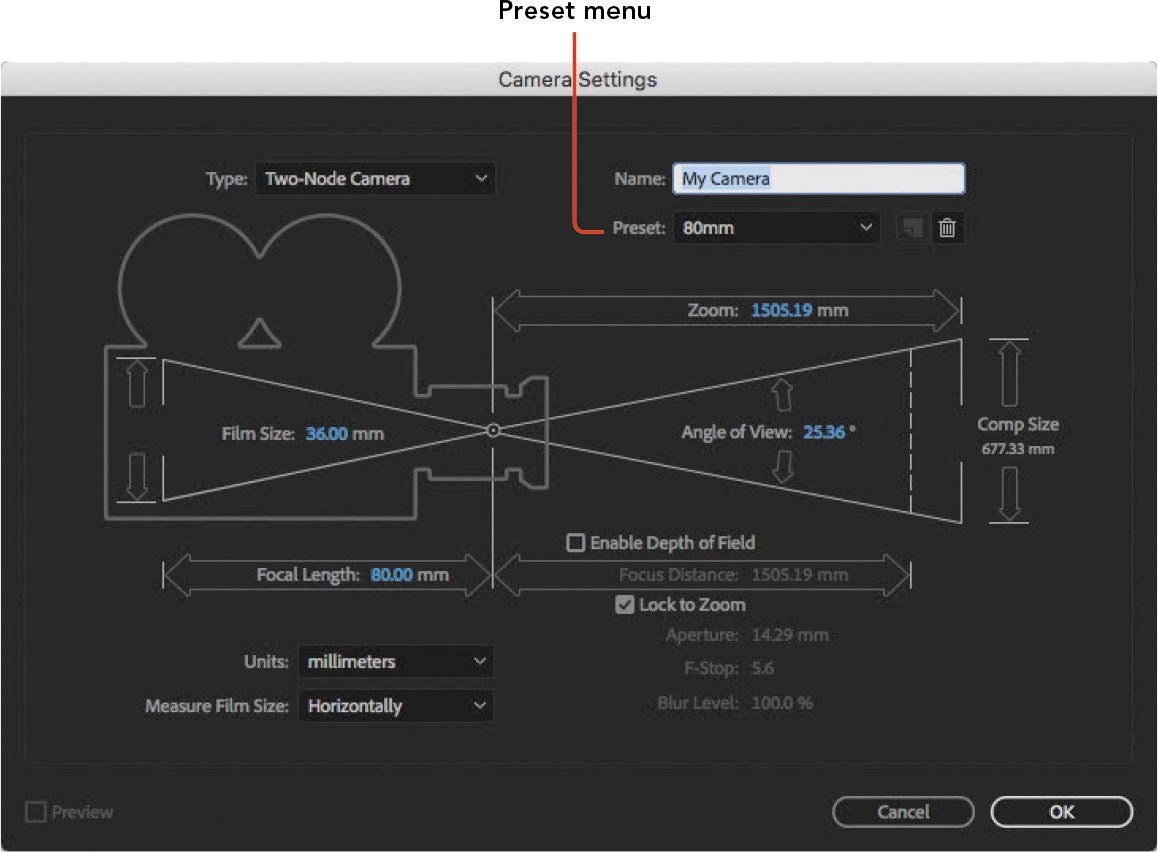
Figure 6.15 Setting up a new camera
Click OK.
The new camera appears as a layer in the Timeline panel.
Now you’re ready to animate camera properties:
In the Timeline panel, expand the Transform and Camera Options properties.
Change the current time to 3:15.
Click the stopwatch for the Point Of Interest property (in the Transform group) to enable keyframe animation for it, and then click the stopwatch for the Zoom property in Camera Options. These are the properties that are animated in Video 6.6.
Change the current time to 4 seconds.
Make sure the left view is active (has blue corners), and then choose Front from the 3D View menu. The right view should be set to Active Camera.
Scrub the Point Of Interest values until the Hot Digity Dog Treats text is centered in the right view (the active camera) (Figure 6.16). Video 6.6 uses Point Of Interest values of 525, 310, 0, but yours may be slightly different depending on how you positioned the layers.
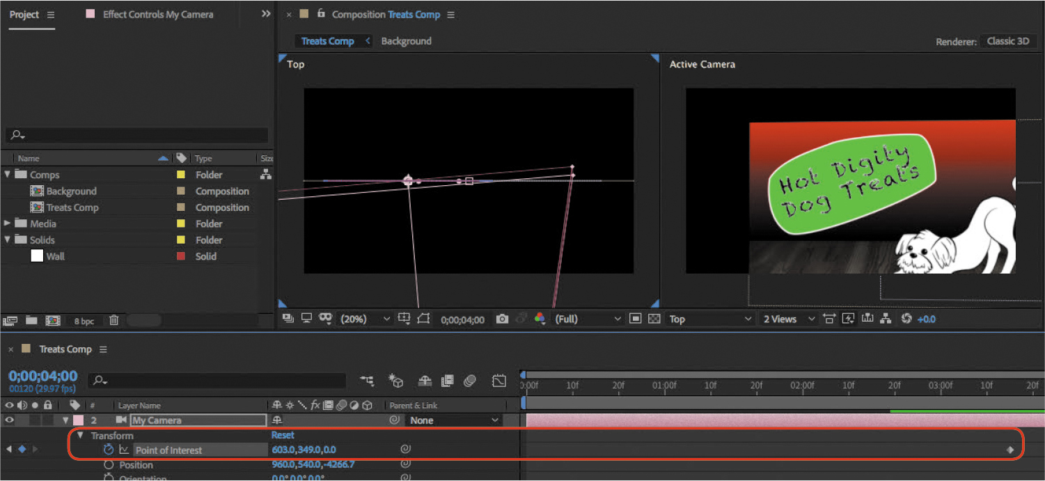
Figure 6.16 Adjusting the camera’s Point Of Interest property
Although the composition appears to move when you animate the Point Of Interest property, the layers aren’t moving. What’s changing is the view of the camera.
Scrub the Zoom value until the text and its background graphic fill the right view (Figure 6.17).

Figure 6.17 Zooming into the brand graphic
Tip
If a value doesn’t change fast enough, hold down the Shift key as you scrub.
As with the Point Of Interest edit, changing the Zoom value doesn’t scale the layers; it zooms the camera lens (changes its focal length).
Play back the composition to test it, make any necessary adjustments, and save your work.
About Lights and the 3D Renderer
Video 6.6 mentions lights. Like a camera, in After Effects a light is a type of layer that works like a light on a movie set, adding light to a scene. You can create one by choosing Layer > New > Light. A light has properties such as Type (for example it can be a Spotlight or a Point light source), Intensity, and Color. A light can cast shadows on layers that are set to accept shadows.
As with cameras, getting the most out of lights requires having experience with their real-world counterparts. If you have experience designing lighting setups for photo shoots or TV/movie sets, you can set up a group of lights on a 3D scene to produce similar results.
Lights really come into play when an After Effects composition contains 3D objects imported from 3D modeling programs. If your 3D models and lighting are created to professional standards, and your After Effects lights are consistent with the lighting on your backgrounds and live-action green screen footage, you can produce convincing animated composites that might be worthy of a major motion picture.
Video 6.6 also mentions the 3D Renderer. To review this, see “The Advanced and 3D Renderer Tabs” in Chapter 1.
When in doubt, leave 3D Renderer set to Classic 3D.
You may have noticed a colored controller that appears in the middle of a 3D layer when it’s selected. That’s a 3D controller (Figure 6.18), which lets you edit a layer’s spatial properties by dragging.
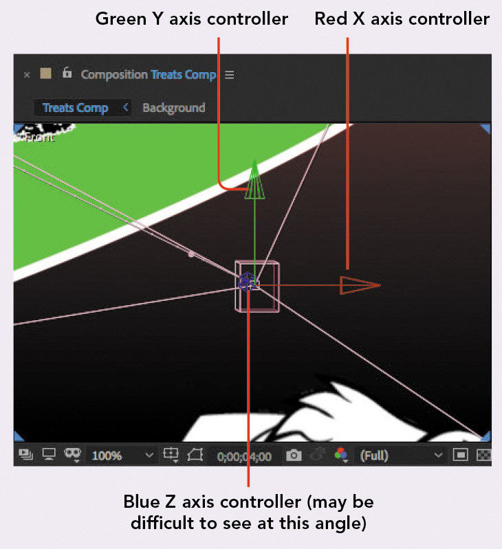
Figure 6.18 The interactive controller for a selected 3D layer
The controller has three colors because each color represents one of the 3D axes. Red represents X, green represents Y, and blue represents Z. An easy way to remember which one is which is that the color sequence RGB (red/green/blue) corresponds to XYZ. Just think “RGB = XYZ.”
To use the 3D controller, select a layer and position the Selection tool over the axis you want to change. When you see that axis’s label appear next to the pointer, drag the mouse. For example, if you position the pointer near the X axis, an X appears next to the pointer and you can now drag. Your drag will be constrained along the X axis; the Y and Z values won’t change.
Reviewing Timeline Panel Switches
![]() ACA Objective 2.2
ACA Objective 2.2
![]() Video 6.7
Video 6.7
Reviewing Timeline Panel Switches
The Timeline panel contains many switches, and you probably haven’t had much time to use all of them.
Still, it’s important to understand what the layer switches do. Video 6.7 reviews some of the more important layer switches. To review them in this book, see “Exploring Layer Switches” in Chapter 1.
Animating Text Along a Path from Illustrator
![]() ACA Objective 4.2
ACA Objective 4.2
![]() ACA Objective 4.7
ACA Objective 4.7
![]() Video 6.8
Video 6.8
Animating Text Along a Path from Illustrator
In Chapter 3 you animated text along a path. That path was drawn using the Pen tool in After Effects. Sometimes paths are drawn in Adobe Illustrator and imported into After Effects. This works because the basic way paths work is the same in both applications, and Illustrator has a much more powerful and specialized set of path drawing tools.
The example in Video 6.8 is very similar to how you’ve animated text along a path before. In short, you attach the path to a text layer as a mask, and then use the Path property of the text layer to select that mask as the path to use. Finally, you animate the First Margin property of the text layer. If you need to review the exact steps, see “Animating Text Along a Path” in Chapter 3.
Here, what’s important is to concentrate on the main difference in this chapter: The path used for the text isn’t drawn in After Effects; it’s from Illustrator.
In Video 6.8, the file text-path.ai is added to the composition. As you learned in Chapter 2 (Figure 2.6), this is an Adobe Illustrator file because its filename ends in .ai and it has an Illustrator document icon.
Before you can use a path in the Illustrator file, it must be converted to an After Effects shape layer. You can review how to do this in “Converting Illustrator Layers to Shape Layers” in Chapter 2.
Another way to bring a path from Illustrator to After Effects is to copy and paste it through the clipboard. This may be acceptable if you don’t need any of the benefits of a linked file.
Challenge
Use what you’ve learned in this chapter to take your own compositions to the next level. For example, find a photo of yourself or someone you know, remove the background, and then animate the arms, legs, and head of the photo using puppet animation.
Take your compositions into another dimension by arranging layers in 3D space. For example, import some images of playing cards and try to build a 3D house of cards in After Effects.
For extra credit, search the web for downloadable 3D models compatible with After Effects, import them, and arrange them in 3D space. You can set up a space battle using 3D spaceship models or build a city skyline out of extruded rectangles. Don’t forget to set up a camera or two, and maybe animate the cameras through the scene.