In this chapter, we will look at the Raspberry Pi camera and how it can be controlled using electronic sensors. This will look at using the camera to take photographs automatically based on a PIR sensor and how to use the camera for creating stop frame animation.
Cameras Available for the Raspberry Pi
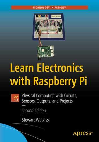
This will start by setting up the Raspberry Pi camera by connecting it to the camera connector directly on the Raspberry Pi. This camera connector has been included on all versions of the Raspberry Pi, except for the early versions of the Pi Zero.
At the time of writing, there are three different official cameras. The camera module V2, the Pi NoIR module V2, and the Raspberry Pi high-quality camera. The first two modules have an 8-megapixel sensor with a fixed focus. The standard module is useful for most general use; the Pi NoIR camera is the same but without the infrared filter suitable for night photography using infrared lighting. The high-quality camera is a 12.3-megapixel camera which needs a separate C- or CS-mount lens to be attached; it provides better quality photos but needs the user to manually adjust the aperture and focus.
All the official cameras use the camera connector. The camera connector provides direct access between the camera and the processor which is more efficient than using a webcam which connects using the USB protocol.
Circuit diagram for the infrared receiver circuit
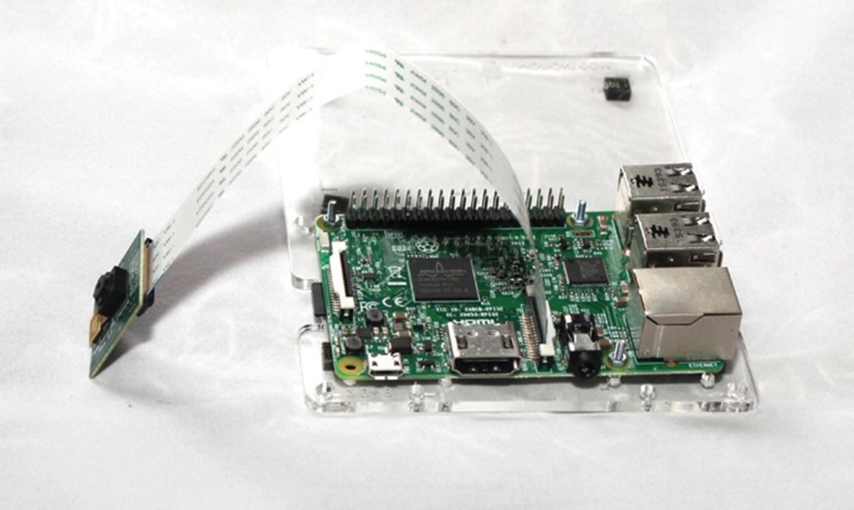
Configuration screen to enable the Raspberry Pi camera
This will take a photograph and store it as photo1.jpg. If you have a screen directly connected to the HDMI port, then you will see a preview prior to the photograph being taken; otherwise, you will just notice a delay before the photo.
Simple program to test the Raspberry Pi camera
This is a simple program which should be easy enough to follow. The first line imports the picamera module. In earlier examples, the from keyword was used which meant that we could use the imported module without referring to the module. In this case, the standard import keyword has been used. This means when you create your object from the picamera module, you need to prefix the instruction with the module name which is picamera.
The code then creates an instance of the picamera object called camera. You can then call the camera methods using this object. The first is called capture. As you can probably guess, this captures a photograph and saves it in a file called photo1.jpg. Finally, the close method is called to clean up the resources that were allocated.
This code has used the same filename as the previous command, so it will overwrite the file created previously. If creating multiple photos, then you will need a way of giving each file a new name. There are two simple ways we could do this. The first is to add a unique number which is incremented for each new file. This involves keeping track of the number. The alternative is to add the date and time to each file, which will make it easy to create the filename. Both options have their pros and cons; I think that using the date is a good way of doing this. This will use the time module and the strftime method which formats the time into a readable date format. The date format used is the ISO 8601 date format, which formats the date in order of the most significant part of the date first. This provides the date in the form of year-month-dayThour:minutes:seconds. The advantages of this date format are that ordering the files by filename will put them into chronological order and that it is a date format that is recognized anywhere around the world. The method time.gmtime() can be used to get the current time, which is in seconds since the UNIX epoch (1970). This is converted to a string which is stored in timestring. It is then included in the filename.
Saving camera photos as a unique name
There is a potential problem with this solution. The Raspberry Pi does not include a real-time clock. If the Raspberry Pi has a network connection (wired or wireless), then it will update the time of the Raspberry Pi using network time servers. If the Raspberry Pi does not have a network connection (such as an outdoor sensor to monitor wildlife), then the date and time may not be correct. If that is the case, the files can be renamed when they are transferred to another computer for later viewing.
Using the PIR Motion Sensor to Trigger the Camera
Chapter 5 showed how a PIR motion sensor could be connected to the Raspberry Pi to detect when someone passes nearby. This can be used in conjunction with the camera to take a photo of the person as they walk near so that you know who has been entering a certain area. It can also be used for detecting and taking photographs of wildlife.
To use the next project, the PIR should be connected to the GPIO as in the diagram in Figure 5-2. The next program will combine the code form the earlier PIR sensor with the camera code. This will wait for motion to be detected and then capture a photo of whoever or whatever triggered the sensor. The files will have the date and time included in the filename.
PIR triggered camera
This code is primarily a merge of the PIR and camera programs listed previously. The main change is for the camera code to be included in the while loop. The camera.close entry has also been removed, as it will continue capturing photos. Ideally, the close should still be called when the program is terminated; however, this code runs continuously (unless it is stopped from Mu or Ctrl-c is pressed), so the close has been removed.
The print statement shows the time that the photograph is taken. This is useful during testing but can be removed once the program is proved to be working correctly.
The code is saved as camera-pir.py which can then be run from the command line. You may want to look at this code running automatically when the Raspberry Pi is started, which was explained in Chapter 7.
Stop Motion Videos
A popular use of the Raspberry Pi and the camera module is in creating stop motion videos. This is where you create a video story by taking photographs for each frame in the video. For a professional video, you may look at taking around 24 photographs for each second of video; for a home video, around ten frames per second would be a good figure. This still needs a lot of photographs to be taken, so to make this easier, this will show how you can add a simple push button to take the photos and then how they can be combined into a video.
Crimp Connections

Crimp tool with female spade connector

Push-button switch with crimped jumper wires
Stop motion camera program code
The code uses sequential numbering of the files, which makes it easier for combining these into a video. To prevent overwriting an existing file, it has an additional while loop to check that the file doesn’t already exist. If the file exists, then it increments the image number until there is no matching file. This uses os.path.isfile which will identify if the filename matches a file.
You will also see that the filename is made up using a complex string. This uses the string.format method. The curly braces {} in the first part of the string are replaced with the arguments passed to the format method. The entry {:03d} ensures that there are always three decimal places in the number which is prefixed with zeros as required.
There are a couple of changes made to the way that the images are taken. The first is to reduce the resolution of the camera to 720 x 576 pixels. This creates smaller files which are easier to merge into a video. This can be left to the default but will create larger files and take longer to process. The other is required because the camera mount I used holds the camera in the upside-down position (with the cable entering from the top). The hflip and vflip attributes have been set to True to turn the camera the correct way around. This is only required if the camera is mounted upside down with the cable coming from above.
The start_preview method is also used to show a preview of the image on the screen before the button is pressed. This is so that you can see what the camera is looking at prior to taking the photograph. One restriction for the preview is that it will only show on a screen physically attached to the Raspberry Pi (e.g., through the HDMI port or if using a Raspberry Pi screen connected to the display adapter). If you want to preview the images through VNC, then you need to enable direct capture mode on the VNC server on the Raspberry Pi.
If you run the program, then it will show a preview and wait for the button to be pressed before capturing the image.
Creating the Film
Now that we have the hardware ready, it’s time to focus on creating the story. Professional stop frame animation normally uses expensive flexible models. A good example of this is the Wallace and Gromit film, which uses models made partly out of clay. If you are good with modeling, then feel free to make your own clay models, but a good way of creating a simple animation on a small budget is to use existing toys such as Lego models. I have used a combination of Lego City and some Lego Friends, although these are not quite to the same scale, they are close enough using the Lego Friends model in the background. You can use any other kinds of models or toys, such as action figures, dolls, puppets, or plasticine monsters.
I also made some backdrops using photos of places that I’ve visited and different colored papers and cards for the base. You could also create model and landscapes using craft materials.
Editing the Video
You should now have a series of files starting with frame0001.jpg up to whatever number of photos that you have taken. These still images can be combined into a video using a script on the Raspberry Pi or by transferring it to another computer first. I will show you how these can be combined into a video on the Raspberry Pi, which is useful if you want to automate the creation of a video, but most likely, you will want to transfer this to a PC or laptop which will provide more flexibility.
This book is about the hardware and software used to capture the photographs rather than being a guide to video editing, but I will provide some of the basics to get you started and some suggestions for special effects.
Creating the Video on a Raspberry Pi
First, we will look at how we can combine the photos into a video using the Raspberry Pi.
As long as the images were padded with the zeros, this will create an MP4 video using the frames in numerical order. This is at a frame rate of ten frames per second, so you will need a lot of frames to create a reasonable length video.
Editing the Video Using OpenShot
The command-line tools such as ffmpeg are OK for automatically combining videos into a sequence, but they don’t offer the same flexibility as a graphical non-linear editor. Fortunately, there is a free editor called OpenShot which can be used either on the Raspberry Pi or on a PC. If running on a Raspberry Pi, then I recommend using a Raspberry Pi 4, preferably with 4GB or more memory. If your Raspberry Pi isn’t powerful enough, then you may prefer to transfer the files to a PC and edit it there.
For OS X or Windows, you can download the program from the following link:
When I installed OpenShot on the Raspberry Pi, it created a launch icon, but for some reason, that is not displayed. That can be fixed by deleting and re-adding the icon through the menu editor, or it can be launched using openshot-qt on the command line.
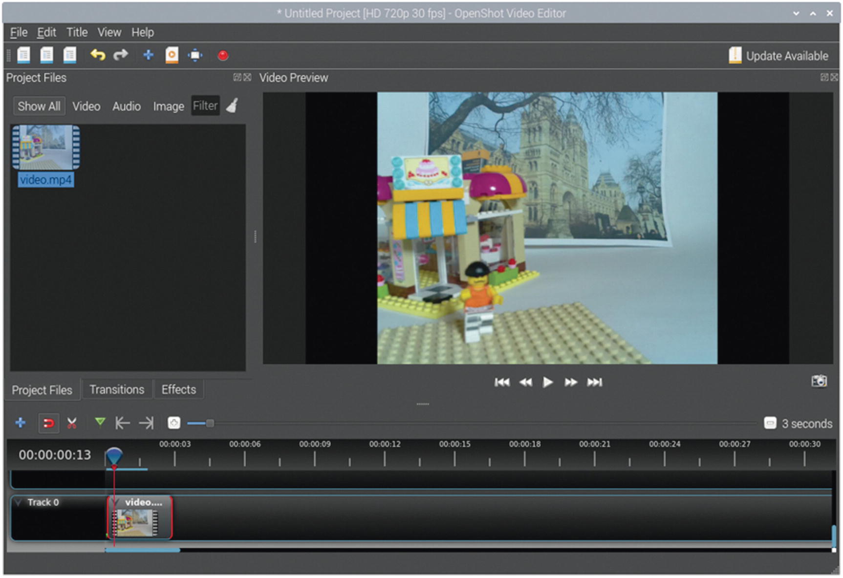
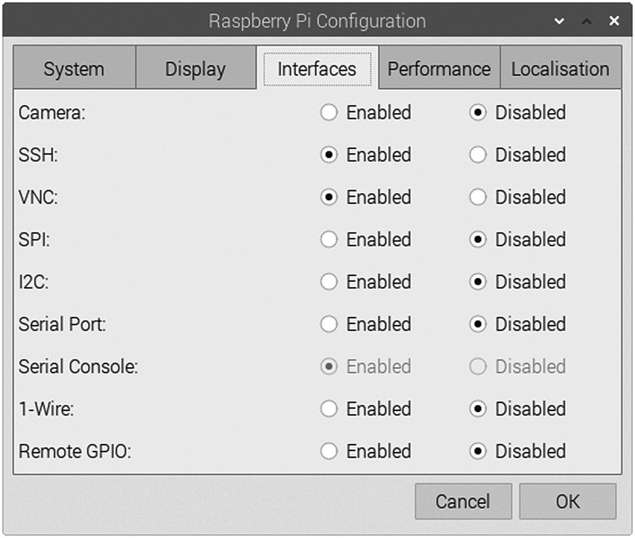
OpenShot with a simple video file
You can combine this video with other video files or photos and then export it in a suitable format.
If you only have the still photos and haven’t yet converted them to a video file, then you can import them directly into OpenShot. This is achieved using Import Files on the File menu. Select all the image files and then click Yes when asked if you would like to import the files as an Image Sequence. This will add the photos but also add a video named frame%03d.jpg. You may need to change the frame rate through file properties, and you can rename the file to something easier to remember. The %03d part of the filename is similar to using :03d in the Python string format. Unfortunately, there are different ways of representing string values in different programming languages or even within the same programming language.
The OpenShot video editor is a fully featured editor which allows you to add other photographs and video, music, or voice over. You will need to use an external microphone (such as a USB microphone) if you want to record voice directly on the Raspberry Pi.
Pan and Tilt Camera
A useful thing for the Raspberry Pi is to have the ability to change the direction that the camera is pointing. This can be achieved using servo motors, which have already been covered in Chapter 6. There is a pan and tilt unit which uses two servo motors that can be connected to the Raspberry Pi. The one used here is created by Pimoroni which is available through several Raspberry Pi suppliers. There are alternatives available, and it is possible to create your own through 3D printing, but this will concentrate on the Pimoroni model.
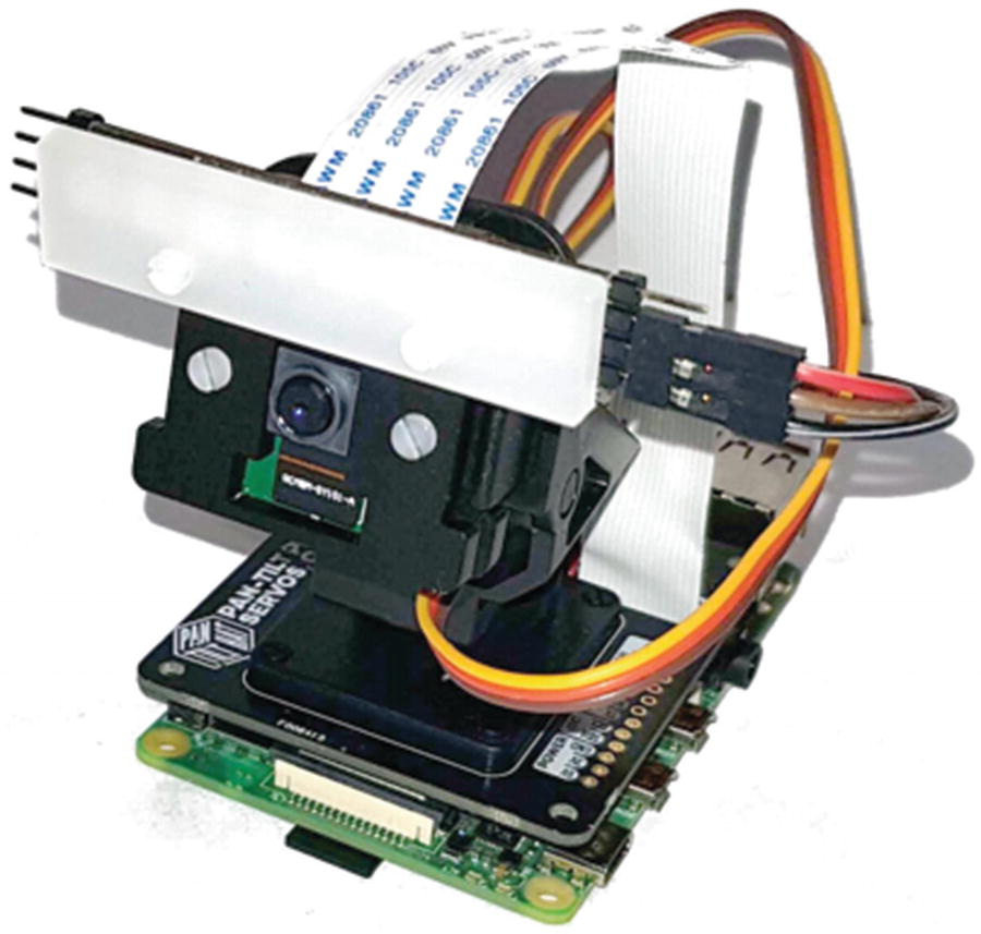
Pan-tilt HAT with Raspberry Pi camera module and NeoPixel light
The pan-tilt module consists of two SG90 servo motors. There is one which connects to the base which provides the pan and one that connects to the clamp for the camera module which provides the tilt capability.
Test program for the pan-tilt HAT
This can be saved as pan-tilt-test.py and when run will move the camera from side to side and top to bottom.
Using Motion to Stream Video
There are a few different ways that video from the camera can be streamed to a web browser. The one used here is called motion, which is free software available at https://motion-project.github.io/.
The reason for changing the port for webcontrol is so that it doesn’t conflict with port 8080 which will be used for the web page for the user to connect to. There are lots of other settings in the file, most can be left at their default values, but you may want to change the width and height for a higher resolution.
You can test that motion is working correctly by visiting http://127.0.0.1:8081/ from a web browser on Raspberry Pi. You can also connect from another computer on the same network by using the IP address of the Raspberry Pi.
Adding a Web Interface
Finally, you can add a web interface to allow the camera to be controlled and viewed from a computer on the network. This will use the same technique as used in Chapter 7 to provide a web interface for the model train.
Web application for pan-tilt camera
Index.html file for the web camera
These files are based on the pan-tilt test program and the web part from the IoT model train code in Chapter 7.
As well as controlling the motor, this code and html file include support for an RGBW light module. This is optional and if not included will have no effect.
More Video Editing
This chapter has given some examples of things that can be done using electronics combined with the Raspberry Pi cameras. It’s looked at using infrared to trigger the Raspberry Pi camera. It then covered stop motion animation, taking photographs using a switch as a trigger and then merging the still photos into a video using the command line and OpenShot.
Another example is in creating a CCTV-style web interface, providing pan and tilt capability using the pan-tilt HAT.
Once you have made your first video, it can be fun to try different techniques and see how they look. You can find that it takes up a lot of time as hand-editing individual frames can be quite time-consuming, but the results can be very rewarding.
You could also look at improving the web interface for the pan-tilt camera such as being able to move to specific scenes. You may also want to add a capture button to save a static picture.
The next chapter will look at creating a robot with the Raspberry Pi.