Scratch is a visual-based programming language. It was designed at MIT for teaching programming to children but has become popular with young and old programmers. Some universities even use it as an introductory language for new students.
The latest version of Scratch is version 3, which is available through a web browser or as a native program on the Raspberry Pi. Unfortunately, Scratch 3 uses a lot of memory and so the native client may not work on older versions of the Raspberry Pi or those with limited memory. To run the native Scratch 3 program on a Raspberry Pi, it is recommended that you have a Raspberry Pi 4 with at least 2GB of memory. For other models, you should use Scratch 2 instead. The Raspberry Pi OS image includes Scratch, Scratch 2, and Scratch 3.
This chapter describes using Scratch 3, which is preferred as it has a similar interface to using a web browser, which is how most people first learn Scratch. If your Raspberry Pi is not up to running Scratch 3, then Scratch 2 is very similar, and the main differences are explained as required.
Introduction to Scratch

Scratch 3 on the Raspberry Pi

The four main areas of Scratch
The most significant difference from Scratch 2 is that these are positioned differently. On Scratch 2, areas A and B are at the left of the screen.
The most important part of the Scratch application is the stage area (section A); this is a representation of the screen when the program is running. The look of the game will be designed on the stage area, and it’s also where you can see the program run. There is also a green flag, which is used to start the program running, and a red stop sign, used to stop the program.
If the screen is a stage, then the sprites are the actors, props, and lights used to create the show. These are stored in the sprite list area (section B). At the bottom of this section, there is a button for adding a new sprite (which is on the top right of that section in Scratch 2). There are different options for drawing your own sprite: choose an existing file (many are included with Scratch), upload your own file, or get a random sprite. In Scratch, a sprite can have its own costumes, scripts, and sounds associated with it. The stage is considered a special type of sprite and is shown next to the sprites list area with the same options for choosing a new backdrop.
If you want to change a sprite, then you load it into the sprite edit area (section C). Sprites are loaded into this section by clicking them in the sprite list, where they will then be shown with a border. There are three tabs in the sprite area called Code (or Scripts), Costumes, and Sounds.
In Scratch, the program code is grouped together into a script which is edited on the code or scripts tab. It is common to have several scripts associated with each sprite. The stage can also have its own scripts, which are often used to control the sprites or the stage background.
The costumes tab is used to change the look of a sprite. It does not need to be a different form of clothing (although that is one use of a costume); it could be used to represent a different object or completely different look, such as a firework rocket which changes to a burst of light when it explodes. When editing the stage, the costumes tab is replaced with a backdrops tab which can be used to change the scene. There’s also a sound tab to add sound to the sprite.
The code blocks area (D) holds the blocks of code that can be built together to make the scripts. Each block of code is shaped with interlocking tabs which can be connected with other appropriate blocks of code.
The blocks of code are grouped into nine different group blocks which are labeled and color-coded the same as the code block color. The code for the sprite is created by dragging the appropriate code block from this area to the code area for the sprite. If you position the block close to another block, then they will snap into place.
Scratch with GPIO Support
The Scratch client includes special code blocks to support access to the GPIO pins. This is added by clicking the icon in the bottom left corner. Clicking that gives several different modules, including Raspberry Pi GPIO and Raspberry Pi Simple Electronics. Either of these modules can be used for this project as they provide very similar options. I recommend the Raspberry Pi GPIO module as it does provide additional options regarding the way inputs work.
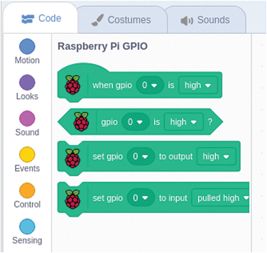
Scratch code block extensions for the Raspberry Pi
Scratch 2 has a similar extension which is chosen using the Add an Extension button. In Scratch 2, there is just one set gpio code block which handles both inputs and outputs, whereas it is split across two different blocks in Scratch 3. Scratch 2 doesn’t have the code start event (the first option in Figure 3-3), but that is not required for the project in this book.
Controlling an LED Using Scratch
Before we create our program in Scratch, you need to create your first Raspberry Pi electronic circuit. You will start off with a very simple LED circuit which allows you to turn a light on and off depending upon events in a Scratch program. This will then be expanded to make our first game.
To understand the circuit, you first need to understand two components, the LED and the resistor. You have already seen these in the previous chapter, but I’ve included a more detailed explanation here.
Light-Emitting Diode (LED)
An LED is a component that gives out a light when an electric current passes through it. The LED is very efficient and so you will often see them used in battery-operated light-up toys. The fact that it doesn’t use much energy is important as the amount of current we can supply from the GPIO pins is very small. If we instead used a light bulb such as those you may have in an older torch, then we would need a more complex circuit or risk damage to the Raspberry Pi.
An important thing about an LED is that it needs to be inserted the correct way around in the circuit. This is due to the diode part of its name. A diode is a component that acts like a one-way valve only allowing current to flow in one direction. As its name suggests, the light-emitting diode emits light when the current is flowing. Depending upon the materials used in the LED, it will light up a particular color.

A typical LED
Resistor
A resistor acts to reduce the current flowing through a circuit. This is particularly important to protect a component from being damaged due to too much current flowing through.

A 220Ω resistor
In this circuit, the resistor is required both to protect the GPIO port from too high an output current and to protect the LED from excessive current. To calculate the value of the resistor, we first need to know the voltage across the resistor and the current we want to limit it to.
The voltage of the GPIO output is 3.3V. Approximately, 2V of this is across the LED, so we have approximately 1.3V across the resistor.
- 1.
Red (2)
- 2.
Red (2)
- 3.
Brown (x 10)
- 4.
Gold
Due to differences in manufacturing, the resistor is not necessarily going to be the same as the specified value. The fourth entry is shown as gold which gives us the tolerance rating (how close the resistor must be to the specified value), in this case, 5%. Taking the tolerance into consideration, the actual resistor will be between 209Ω and 231Ω.
This book is about teaching electronics, so the full calculation has been shown. The calculations are not particularly difficult, but there are also online resistor calculators which could be used if you would rather concentrate on the creativity rather than the math.
Connecting the LED to the Raspberry Pi

LED circuit for Scratch GPIO
Remember to make sure that the LED is the correct way. Looking at the diagram in Figure 3-6, the longer wire should be the one nearest the top, which is in the same block as the resistor. I have deliberately bent the leg on the diagram to make the anode (positive side) look longer. Do not worry if your wiring does not follow the exact same layout as shown in the diagram; the length of the legs on the components may make it easier to position slightly differently. The important thing is to connect to the correct ports on the Raspberry Pi and for the components to connect to the same row on the breadboard where required.

Initial LED script
With Scratch 2, the code will look similar, although the Raspberry Pi blocks will be a dark gray color instead of green. If you click the green flag, then the program should run which will turn the LED on for 1 second and then off for 1 second. The code will continue to run turning the LED on and off one second at a time. Here’s an explanation for how it works.
The block containing the green flag at the top of the script is from the event blocks. It has a curved top which indicates that this will start this script running. It is used to start the script whenever the green flag is clicked to start the program. All scripts should start with a start block, most of which are event blocks.
The forever block is from the control blocks and creates a loop which will run “forever”. It runs any code between the forever at the top and the white arrow at the bottom of the loop. When you drag the block over, you will see it has a blank section in the middle, which is where you drag the code blocks that need to be run inside the loop. Although it is called forever, it will likely not actually run forever but will continue to loop while the program is running, until you click the red stop sign to stop the program.
The wait blocks are also from the control blocks and pause the script for running for a set length of time, in this case, 1 second. You can change the value in the wait, try changing it to a decimal fraction (say, 0.5), and see what happens.

As the wording on the block suggests, this will set the gpio output value. You can choose the GPIO number from the pull-down list where it shows 22. As explained in Chapter 2, GPIO port 22 is the port that is connected to GPIO 22 on the processor, which is not the same as the physical pin number. The physical pin number that we have connected to is 15. Saying to turn an output high will set its output voltage to 3.3V which is the high or on value. This will turn on the LED. Turning an output low is the same as turning the output off and setting the voltage to 0V.
Adding an Input to the Scratch GPIO Program
Using the LED circuit (Figure 3-6) as a starting point, we will now add an input to the Raspberry Pi. Inputs can take many different forms; in this case, we will be using a simple switch.
Switch
A switch is used to create a break in a circuit or join two parts of a circuit together depending upon the position. There are different types of switches depending upon what the switch is being used for. The one we will use here is known as a push-to-make push-button switch. When the button is pressed, then it pushes the conductors together inside the switch completing the circuit. This is like a doorbell push switch which completes the circuit causing the doorbell to sound. When the switch is not pressed, then that is known as being open as the contacts inside open apart creating a break in the circuit. When the switch is pressed, it closes the contacts together completing the circuit, so it’s known as being closed.
I recommend using a miniature push-button switch of the type shown in Figure 3-8, which is the same as shown previously in Chapter 1. This switch has four pins, although the pins on each side are connected together with just a single switch in the package. The ones I have used include clip-on button caps which make them stand out a bit more. The caps are not necessary and only fit on certain switches.

Push-button switch and circuit diagram showing connections
Using a Switch As a Digital Input
The GPIO port needs to be sent a digital on or off signal, which should be +3.3V for on and 0V for off; this is the same as the high- and low-output states. At first thought, you may consider using the switch to connect to the positive supply and rely on the pin being disconnected for a low 0V signal. Unfortunately, that is unlikely to work as when the power is disconnected, the input will be considered floating. When an input is floating, then the state is unpredictable and can often change between high and low.
Instead, we need to connect the input to the positive voltage so that the supply is high when the switch is not pressed. The switch then connects the pin to the 0V supply to bring it low when pressed. A high-value resistor (usually in the tens of kΩ) is required for the connection to the positive rail to prevent a short circuit. The Raspberry Pi has internal pull-up resistors that can be used rather than needing to add an external resistor. The pull-up resistors can be enabled using the input block from the Raspberry Pi extension with the state “pulled high”. The Raspberry Pi also supports “pulled low” where you connect the switch between the GPIO port and the 3.3V supply, but it is more common to have the Raspberry Pi pin pulled high and then use the switch to pull it low.
Adding the Switch to the Circuit

Switch and LED circuit
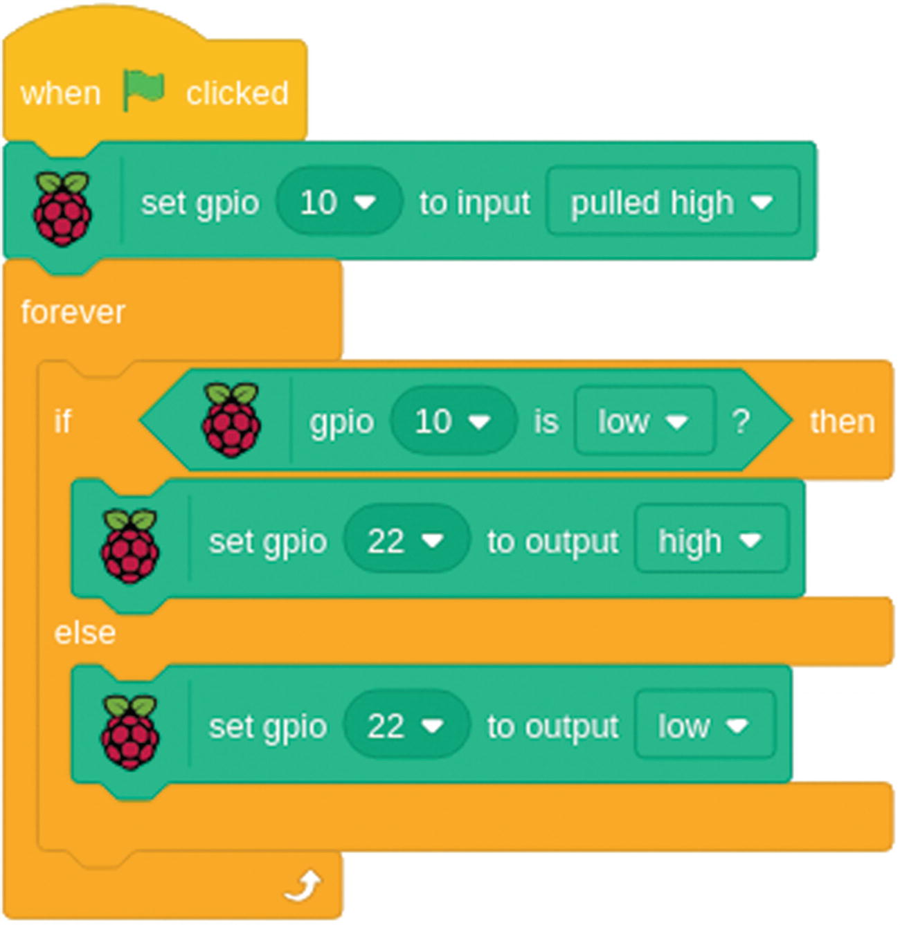
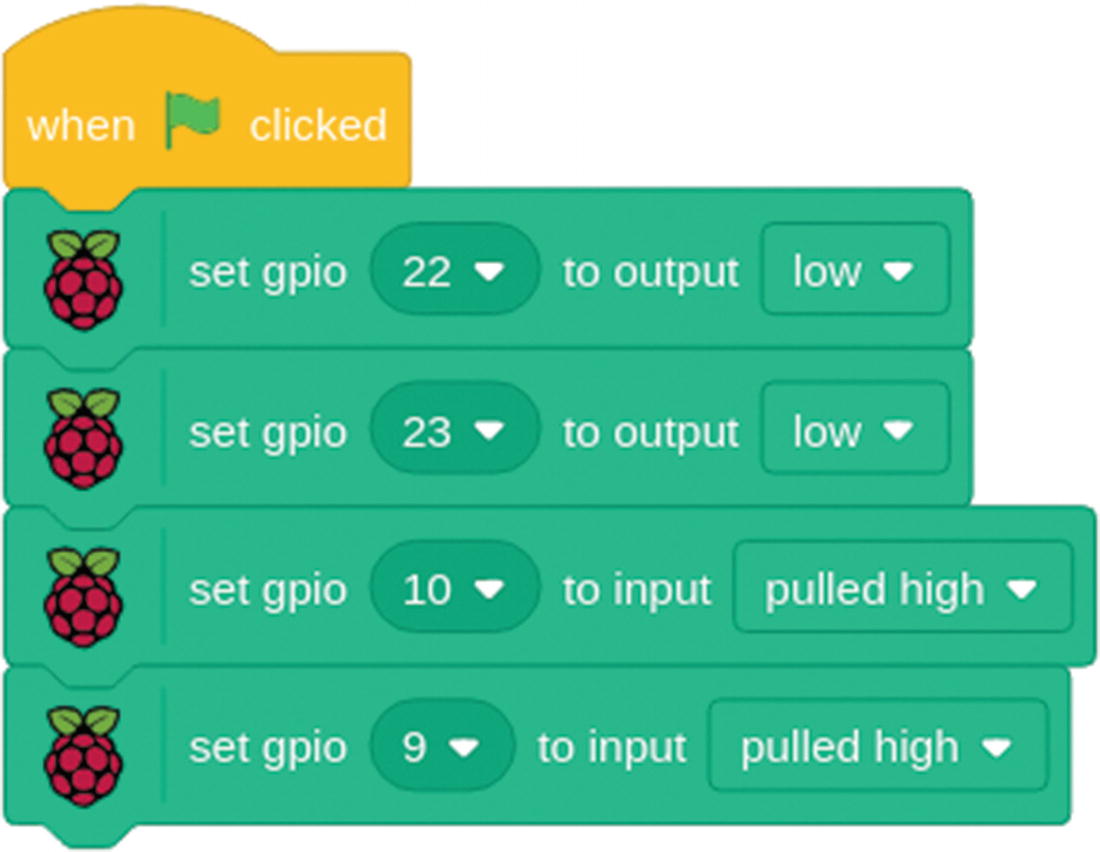
Switch and LED Scratch code
I have added a new block at the start sets GPIO port 10 as an input with a pull-up resistor.
In the forever loop, the GPIO block is used to check on the status of the switch. If the switch is not pressed, then the internal pull-up resistor sets the value to high. When the switch is pressed, then the input is pulled low by the switch and the sensor value will be low.
When the code has been entered and the program run, then the LED will be initially off, turning on when the switch is pressed and off when it’s released. This is effectively performing the same as the LED circuit in Chapter 1, but now using an entire computer where the switch was able to handle this on its own. We have done this to introduce the way that inputs and outputs are handled in Scratch. We will now be adding a few more components and creating a game in scratch based on this circuit.
Robot Soccer

Robot Soccer game

Circuit for Robot Soccer
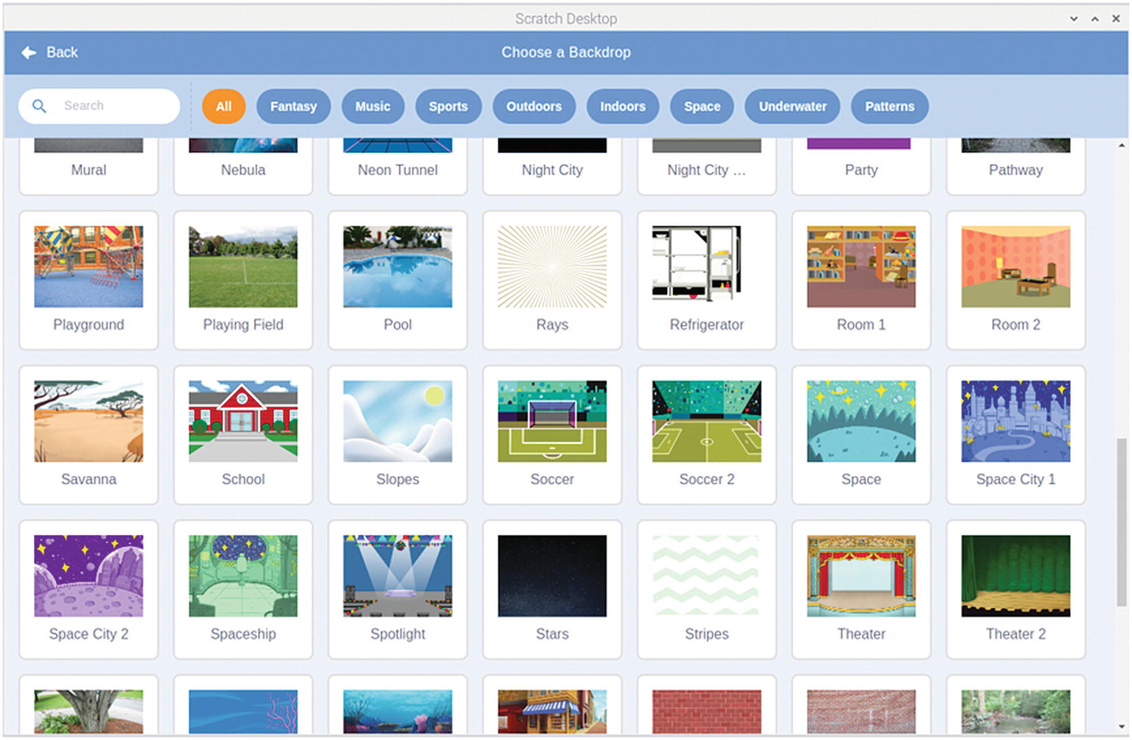
Adding the background for Robot Soccer
Rather than editing the previous Scratch project, start a new one. Click File ➤ New which will create a new project with the Scratch cat sprite. Delete the cat sprite as that is not required. Click Choose a Backdrop and choose the Soccer backdrop image. This is shown in Figure 3-13.
Setup code for Robot Soccer game added to the stage scripts tab

Adding a new sprite using the Robot sprite
There are lots of alternative sprites you could choose instead – whether you prefer the giant hand called Goalie, a dinosaur, or one of the people sprites. Change the size of the sprite to 50 and move the sprite so that it is centered in the goal posts.
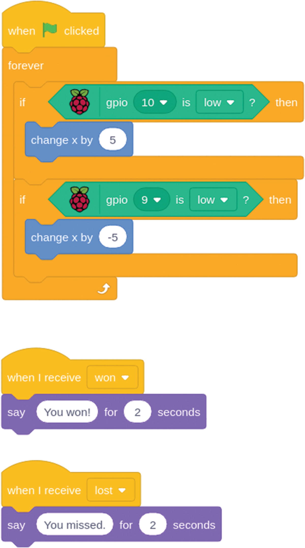
Code to add to the scripts tab of the robot sprite
The main part of the code on the robot sprite is a forever loop, checking for the status of the two GPIO pins 9 and 10. This is similar to the forever loop in the previous Scratch project, but using two switches to move the sprite across the screen. If a button is pressed, then it increases or decreases the x position of the sprite, which makes the robot move left and right as appropriate. One thing that you may notice is that based upon Figure 3-12 the switches are the wrong way around. It is easier to turn the circuit upside down when it comes to play the game so that you don’t need to reach over the Raspberry Pi when playing.
The other two code blocks receive a broadcast message and use the say command to show a message. The broadcast messages are a way of sending messages between different scripts. When you add these, you will need to choose new message to define the broadcast messages. The broadcast message is sent by our final sprite which handles the rest of the logic.

Adding the ball sprite

Code for the ball sprite
This code is a little more complicated than the previous code snippets, so this will be explained in more detail.
The first thing the code does is to set the size of the sprite to 100% and position it to the center front. During gameplay, the ball size will reduce to make it appear to go into the screen toward the goal. Setting the size back to 100% will reset the ball if it is still at a reduced size from a previous game. The set size block comes from the looks blocks, and the go to block is from the motion blocks.
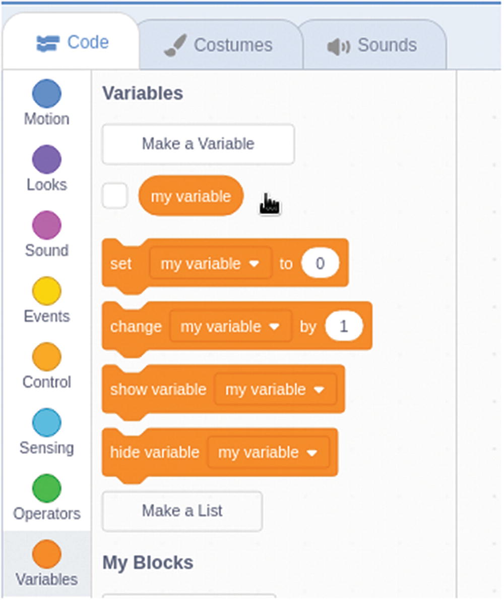
Creating a variable in Scratch
Next, you can set the variable to a random number by using the pick random from the Operators code blocks. The random number should be between –10 and 10.
The following block is a repeat block which will run the code to move and change the size of the ball ten times. The x direction changes based upon the direction variable. If the random number happened to be a large number (up to the maximum of 10), then the ball will go all the way over to the right; if it’s a small number, then it will be near the center of the screen; if it’s a large negative number, then it will go to the left. The y position has been changed slightly to make it appear as though the ball is rolling up the field. We also make the ball decrease in size as though it is getting closer to the robot. There is also a wait code block from the control blocks which slows the game down slightly.
Once that has repeated ten times, the repeat loop will finish, and it progresses to the if block. This tests to see if the ball sprite is touching the Robot sprite. If you chose a different sprite, then the name of your sprite should appear on the pull-down list instead.
The code then sends two broadcasts. If the ball was touching, then the robot managed to get to the ball; it turns the green LED pin high and sends a broadcast “won” which will trigger the robot to say “You won!” If the robot did not get to the ball, then it will turn the red LED pin high and trigger the “You missed!” message.
The code then waits for 2 seconds before switching the LEDs off again by setting them low. Note that it turns off both LEDs even though one is already off. Obviously, turning something off when it’s already off will not do anything. We could have instead had a variable and an additional if statement, so we only sent the message to the LED that was switched on; it’s a matter of personal choice which you prefer.
Playing Robot Soccer
Now that it is complete, you can play the game. The game has been designed to be mounted on a board which is turned around so that the breadboard and button are on the bottom. I have used a Raspberry Pi breadboard mount, but you could use a thin piece of wood or thick card.

Finished controller for Scratch Robot Soccer
Click the green flag in the top right of the scratch stage to start. Press the left and right buttons to move the robot from side to side to stop the ball. The green LED will light up if you win and the red LED if you lose. Click the green flag to start again.
More Games
This chapter has looked at using a simple circuit based around the Raspberry Pi with LED outputs and switches as inputs. This has formed the basis of a simple controller for controlling a computer game.
The game can be changed to create your own personal game. If you don’t like soccer, then change it into a tennis game or use the controller for a more complicated game.
The next chapter will look at using Python instead of Scratch and controlling some bigger and brighter outputs.