
When we need to connect two bodies together in Box2D, we use joints. Joints always connect two bodies and never more. Multiple joints are then required to link more bodies together. A joint always connects a dynamic body with another body that can be either static, kinematic, or dynamic. Joints between kinematic and static bodies are allowed but have no effect.
A joint can also specify whether the connected bodies should collide or not. We are going to see the basic joints available in Box2D, and we are going to implement one of them.
The revolute joint is like a pin or hinge. Imagine that you cut two bodies from some paper and pin them together. The pin hole in the first body is the first anchor and the hole in the second body is the second anchor. The bodies are linked with the pin and both can rotate around that point.
What's a bit hard to imagine is that the pin hole can actually be outside the bodies. We can think of this as if there was a small invisible solid unbendable wire with a little eye. Here's how a typical revolute joint looks:
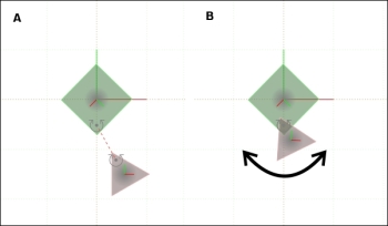
The joint is defined between a static square and a dynamic triangle. The circle arrows indicate where the joint anchors are. When we run the simulation, the triangle will be translated to the correct position and will then start rotating around the anchor.
A typical use for a revolute joint is a simple wheel on a cart, clock hands, or basically anything that revolves around a point.
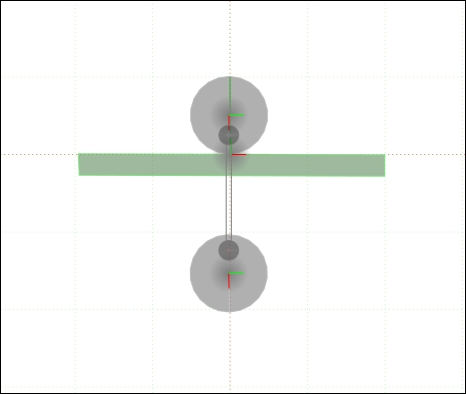
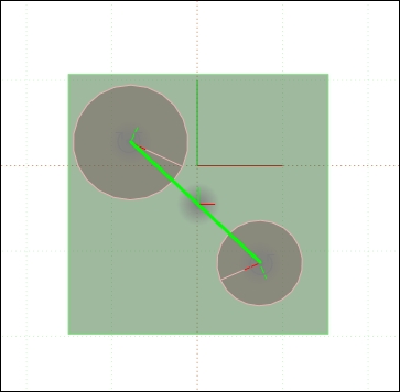
The distance joint defines anchors in two bodies and a length. The two anchors will always keep the distance defined by the fixed length. We can imagine this joint as a steel rod mounted at the anchor positions between those two bodies. The bodies can rotate around the anchors unless they are defined with a fixed rotation. In the following figure, you can see two circles kept at the fixed distance.
The top circle rests on top of a static body. Without the joint, the lower circle will fall due to gravity.
Two bodies linked with a prismatic joint will keep their relative rotation. If you rotate one, the other one will rotate too. However, they have one degree of freedom, they can move along a defined axis. We can imagine this as an elevator moving only up and down in the elevator shaft or a cylinder in a car's engine. The piston will move forward (up) and backwards (down) no matter how do you rotate the whole engine. Pistons and elevators are a typical use of this joint.
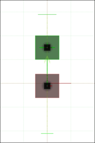
The prismatic joint can define a limit that will limit the movement (distance) of the bodies. In the following figure, the limit is shown and two thin green lines. The axis of movement is a green arrow. The upper body is static, so only the lower body moves. It can move as much as the limits permit.
The prismatic joint can also have a motor, which means that the bodies will try to move at a specified speed along the joint.
The line joint is exactly the same as the prismatic joint, but the attached bodies can rotate. It is used to model vehicle suspensions.
The friction joint adds friction between two bodies and thus reduces their relative speed. This joint is defined by the two bodies and a force. We can imagine it as a magnetic repulsive force between the two bodies.
The pulley joint has two anchors, and the length from the first anchor to the first body summed with the length from the second anchor to the second body is always the same. Here's a typical example of how it works:
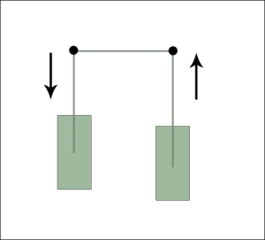
The behavior can be changed by a constant that will make one of the ropes extend and contract constant times faster than the other side.
The gear joint is the only joint that connects two other joints. We still have to define two bodies but we must also pass two joints to the gear joint. Let's say we have one static body called Ground and two dynamic smaller bodies, A and B, attached to the ground using a revolute joint. When we define a gear joint between A and B, we also have to pass the joints' Ground-A and Ground-B joint definitions to the gear joint. Then, the Ground-A joint makes A move, and B will move as well. The revolute and prismatic joints can be linked with a gear joint.
The last joint is called the mouse joint and it is special because it only requires one body, but still two bodies must be passed in. One of the bodies is the body that we want to move and the other one can be any body.
A mouse joint is used to move a body to another location. Basically we define a point (anchor) on a body and a target. It will look as if we have attached a string at the anchor and pulled the string towards us while standing at the target location. The properties of the string can also be defined. For example, we can make the string to elastic and the body will bounce around the target before settling in.
A typical use for the mouse joint is a go-to feature or the drag-and-drop feature in physics-based games.
The good thing about joints is that most of them can be defined the same way, just some parameters and the final effect differ. Here's a simple way to attach one of the temporarily added bodies to the player's body. The code belongs to the populate() method of the GameScene class. We have removed the temporary bodies except the circle and we no longer need filtering:
  @Override
  public void populate() {
    createBackground();
    createPlayer();
    //camera.setChaseEntity(player);
    createHUD();

    addPlatform(240, 100, false);
    addPlatform(340, 400, false);
    addEnemy(140, 400);

    engine.enableAccelerationSensor(activity, this);
    registerUpdateHandler(physicsWorld);

    //physicsWorld.setContactListener(new MyContactListener(player));

    setOnSceneTouchListener(this);

    FixtureDef circleFixture = PhysicsFactory.createFixtureDef(1f, 0f, 2f, false);
    Body circle = PhysicsFactory.createCircleBody(physicsWorld, 80, 440, 25, BodyType.DynamicBody, circleFixture);
    circle.setFixedRotation(false);

    RevoluteJointDef revoluteJointDef = new RevoluteJointDef();
    revoluteJointDef.bodyA = player.getBody();
    revoluteJointDef.bodyB = circle;
    revoluteJointDef.localAnchorA.set(new Vector2(-1, 0));
    revoluteJointDef.localAnchorB.set(new Vector2(0, 0.6f));
    revoluteJointDef.collideConnected = false;
    physicsWorld.createJoint(revoluteJointDef);

    DebugRenderer dr = new DebugRenderer(physicsWorld, vbom);
    dr.setZIndex(999);
    attachChild(dr);
  }
The highlighted code sets the rotation of the circle to false. Without this, the revolute joint would be just a weld joint in the end. To create a joint, we start by creating the appropriate definition, in this case, the RevoluteJointDef object. We set both bodies and then set the local anchors. The anchor A defines the point of attachment one meter to the left from the player's center. The anchor point B defines the point of attachment in the top part of the circle, 0.6 meters up from the center. We also turn off the collisions between the bodies. Finally, we call the physicsWorld method to create the joint.
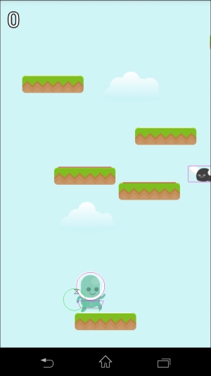
When we run the game now, the character will have a small circle attached to its head that swings freely around the point of attachment. The effect is visible because there isn't any sprite attached to the circle, only thanks to the debug renderer.
We can also configure a motor in the joint that will make the circle rotate automatically. The player's character will not rotate because it is configured with a fixed rotation set to true, as follows:
    revoluteJointDef.motorSpeed = 100f;
    revoluteJointDef.maxMotorTorque = 20f;
    revoluteJointDef.enableMotor = true;
The motor speed is the target speed, and the torque is a rotational force that it can use to get to the target speed. Setting this as low will make the motor reach the final speed very slowly and vice versa.