This chapter focuses on component and deployment diagrams, which depict the implementation and environment of a system, respectively. First, I introduce component and deployment diagrams and how they are used. Next, I discuss components and nodes, which are elements depicted on those diagrams. Finally, I discuss various relationships relating to components and nodes. Many details of our project management system that were not fleshed out in Chapter 2 are more fully elaborated here, and throughout the chapter, I include suggestions relating to component and deployment diagrams.
Component modeling is a specialized type of structural modeling concerned with modeling the implementation of a system. Using the UML, you can communicate the implementation of a system using component diagrams. You usually apply component modeling during design activities to determine how implementation activities will build the system; that is, to determine the elements of the system on which implementation activities will focus. Component modeling typically starts after the design of the system is fairly complete, as determined by your system development process.
Deployment modeling is a specialized type of structural modeling concerned with modeling the implementation environment of a system. In contrast to modeling the components of a system, a deployment model shows you the external resources that those components require. You typically apply deployment modeling during design activities to determine how deployment activities will make the system available to its users; that is, to determine the elements of the system on which deployment activities will focus. Like component modeling, deployment modeling usually starts after the design of the system is fairly complete, as determined by your system development process.
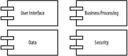
As mentioned in Chapter 2, a component is a part of the system that exists when the system is executing. For example, the project management system may be decomposed into the following components:
- A user interface component
Responsible for providing a user interface through which users may interact with the system
- A business-processing component
Responsible for implementing business functionality, including all the project management functionality provided by the project management system
- A data component
- A security component
Provides various forms of security functionality to the business-processing and data components, including user authentication and verifying user privileges when accessing data
Components follow the type-instance dichotomy first discussed in Chapter 2 and applied to classes and objects in Chapter 3. You can use the UML to talk about classes of components as well as specific components of a class. When speaking of a class of components, it’s customary to use the terms component or component class. Thus, while you might think of a component as a specific thing, in the UML, a component really represents a class of things. When speaking of a specific component of a class, use the term component instance.
A component exists during execution time and requires a resource on which to execute, which I talk about in the next section, Section 5.2. In the UML, a component is shown as a rectangle with two small rectangles protruding from its side. The rectangle is labeled with the name of the component class.
Figure 5-1 shows various components associated with the project management system, including user interface, business-processing, data, and security components.
A component instance is a specific component. For example, specific components of the project management system include:
- A web user interface component instance
Allows users to access the project management system via the Web
- A client/server user interface component instance
Allows users to access the project management system in a client/server environment
- A local data component instance
Stores project management data for a specific user or group of users
- An enterprise data component instance
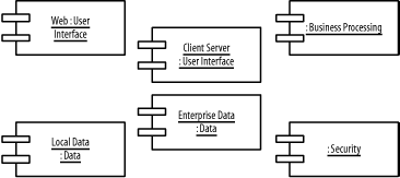
A component instance is shown similar to a component class, but is labeled with the component instance name followed by a colon followed by the component class name, with all parts of the name fully underlined. Both names are optional, and the colon is present only if the component class name is specified.
Figure 5-2 shows various component instances of the
component classes in Figure 5-1, including two user
interface component instances, named Web and
Client
Server, two data
component instances, named Local
Data and Enterprise
Data, a nameless business processing component
instance, and a nameless security component instance.