This chapter focuses on state diagrams, also known as statechart diagrams, which depict the lifecycle of elements that make up a system. First, I introduce state diagrams and how they are used. Next, I go over states and their details. Finally, I discuss transitions between states and their details. Many details of state diagrams that were not fleshed out in Chapter 2 are more fully elaborated here, and throughout the chapter, I include suggestions relating to state diagrams.
State modeling is a specialized type of behavioral modeling concerned with modeling the lifecycle of an element. You usually apply state modeling in conjunction with interaction and collaboration modeling (Chapter 6) to explore the lifecycle of interacting and collaborating elements.
As discussed in Chapter 2, as elements communicate with one another within a society of objects, each element has a lifecycle in which it is created, knows something, can do something, can communicate with other elements to request processing of those other elements, can have other elements communicate with it to request processing of it, and is destroyed. A state is a specific condition or situation of an element during its lifecycle. Define the states for your elements. The current state of an element is called its active state, and the element is said to be “in” that state. There are various types of states, including simple, initial, and final states. The next few sections discuss these different types of states.
A simple state indicates a condition or situation of an element. For example, the project management system may be in one of the following simple states:
-
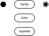
Inactive Indicates that the project management system is not available to its users, because it is not started or has been shut down
-
Active Indicates that the project management system has been started and is available to its users
-
Suspended Indicates that the project management system has encountered some severe error, perhaps because it is running low on secondary storage and requires user intervention before becoming active again
In the UML, a simple state is shown as a rectangle with rounded corners and labeled with the name of the state or a description of the situation of the element. Figure 7-1 shows the various states associated with the project management system.

An initial state indicates the state of an element when it is created. In the UML, an initial state is shown using a small solid filled circle. A final state indicates the state of an element when it is destroyed. In the UML, a final state is shown using a circle surrounding a small solid filled circle (a bull’s eye). Figure 7-2 updates Figure 7-1 with an initial state and final state. A state diagram may have only one initial state, but may have any number of final states.