
Drawing a window usually means drawing a rectangular region filled with information. This recipe will show you how to do this efficiently with new capabilities that OpenGL can offer, such as vertex buffers and shaders.
You could be tempted to put the window corner coordinates into the vertex buffer, which is fine for static windows. However, soon you would realize that it is harder to manipulate a window. To move your window, you'd need to change the window coordinates, which would mean changing the content of the vertex buffer. As you already know, moving data from CPU to GPU is a slow process and it basically halts the GPU processing for a while. A better solution to this would be putting static unit-sized window coordinates and transforming it with a model-view matrix. Matrices can be updated by using uniform variables as they tend to be much faster than doing buffer updates. This gives you an incredible amount of power for drawing a window because you can use those matrices in window positioning, hierarchy, and various visual effects.
This recipe will use a matrix manipulation library in the sample code for matrix operations. You can get one from the GitHub repository at https://github.com/soulik/matrix. A short introduction to this library is a part of the GitHub page as well.
You'll need to prepare at least two vertex buffers. One for vertex coordinates and one for texture coordinates. You'll also need the vertex array object, which will bind these buffers to your shader code. The good thing is that you can reuse this vertex buffer for all the windows you'll ever use.
The last thing you'll need are two matrices: the projection matrix and model-view matrix. The projection matrix will transform view space into a more suitable coordinate system. OpenGL uses coordinates within the range of (-1,1) for both horizontal and vertical directions. This might be valid in a case where you need your UI to scale with the screen resolution. If you want to render textured windows with pixel-perfect size, you'll need to transform the coordinate system into (0,screen_width) and (0,screen_height) respectively.
The model-view matrix will move and scale your rectangle into a desired position on the screen. This means that each window will have its own model-view matrix.
In the first step, you'll fill vertex buffers to create the basic window shape. The code you'll be using will look like this:
local vertex_buffer_object = gl.GenBuffers(2)
local vertex_array_object = gl.GenVertexArrays(1)

-- vertex coordinates
local vertex_positions = {
  -0.5, 0.5, 0,
  0.5, 0.5, 0,
  0.5, -0.5, 0,
  -0.5, -0.5, 0,
}
gl.BindBuffer(gl_enum.GL_ARRAY_BUFFER, vertex_buffer_object[1])
gl.BufferData(gl_enum.GL_ARRAY_BUFFER, vertex_positions, gl_enum.GL_STATIC_DRAW)

-- texture coordinates
local vertex_texcoords = {
  0, 0,
  1, 0,
  1, 1,
  0, 1,
}
gl.BindBuffer(gl_enum.GL_ARRAY_BUFFER, vertex_buffer_object[2])
gl.BufferData(gl_enum.GL_ARRAY_BUFFER, vertex_texcoords, gl_enum.GL_STATIC_DRAW)

-- bind vertex buffers to vertex array object
gl.BindVertexArray(vertex_array_object[1])

-- bind vertex coordinates
gl.BindBuffer(gl_enum.GL_ARRAY_BUFFER, vertex_buffer_object[1])
gl.VertexAttribPointer(0, 3, false, 0)

-- bind texture coordinates
gl.BindBuffer(gl_enum.GL_ARRAY_BUFFER, vertex_buffer_object[2])
gl.VertexAttribPointer(1, 2, false, 0)

-- enable vertex attributes in shader code
gl.EnableVertexAttribArray(0)
gl.EnableVertexAttribArray(1)
The second step will deal with the shader code for the UI. It's better to have one for each logic part of your application as it makes experimenting and spotting bugs easier in the future.
The shader code will consist of the vertex and fragment shader code. The vertex shader code will look like this:
#version 330

layout (location = 0) in vec3 VertexPosition;
layout (location = 1) in vec2 VertexTexCoord;

out VertexData {
  vec2 TexCoord;
} outData;

uniform mat4 projectionMatrix;
uniform mat4 modelviewMatrix;

void main(){
  gl_Position = projectionMatrix * modelviewMatrix * vec4(VertexPosition.xyz, 1.0);
  outData.TexCoord = vec2(VertexTexCoord.st);
}
To complete this part, you'll need the fragment shader code as well:
#version 330

uniform sampler2D diffuseTexture;
uniform mat3 UVmatrix;

in VertexData {
  vec2 TexCoord;
} inData;

layout(location = 0) out vec4 diffuseColor;

void main() {
  vec2 texSize = vec2(textureSize(diffuseTexture, 0));

  mat3 UV = matrixCompMult(UVmatrix, mat3(
    1/texSize.s, 1, 1/texSize.s,
    1, 1/texSize.t, 1/texSize.t,
    1/texSize.s, 1/texSize.t, 1
  ));

  vec2 finalTexCoord = (vec3(inData.TexCoord.s, 1 - inData.TexCoord.t, 1) * UV).st;

  diffuseColor = texelFetch(diffuseTexture, ivec2(finalTexCoord.s*texSize.s, finalTexCoord.t*texSize.t), 0);
}
Now, in the third step, you'll have to fill the content of uniform variables. For this task, you can use the setUniform function from the previous chapter, which will make setting uniform variables much easier. There are two matrices in the vertex shader code to be filled. The first one is for camera and second one is for a placement of your window. Fragment shader code uses the texture unit identifier and the UV mapping matrix. The UV mapping matrix can be set to identity, if you're not using a texture atlas. Remember that you don't have to set uniform variables in each drawing frame as they are stored in the GPU memory for each shader program. Also, don't forget to activate the shader program before setting up uniform variables:
setUniform('m', 'projectionMatrix', projectionMatrix, 4, 4, true)
setUniform('m', 'modelviewMatrix', modelviewMatrix, 4, 4, true)
setUniform('i', 'diffuseTexture', texture_unit)
setUniform('m', 'UVmatrix',{
  1,0,0,
  0,1,0,
  0,0,1,
  }, 3, 3, true)
The projection and model-view matrices will use the homogenous transformation matrix for affine transformation. There are four basic forms of transformation: translation, rotation, scale, and skew. These can be combined with multiplication to produce any desired transformation. Remember that the order of matrix multiplication is extremely important. For example, applying translation after rotation is different from translation followed by rotation.
The projection matrix can be obtained with this code:
local matrix = (require 'matrix')()
local T,S = matrix.translate, matrix.scale
local invW, invH = 1/screen_width, 1/screen_height
local invMaxDepth = 1/16378
projectionMatrix = T(-1, -1, 0.01)*S(2, 2, 1)*S(invW, intH, - invMaxDepth)
This will transform screen space to match the screen resolution except that the (0,0) coordinate will correspond to the bottom-left corner.
The next and most important step is to generate the model-view matrix. This will determine the position of the resulting window. Depending on your needs, the model-view matrix will be constructed from translation and scaling transformations:
modelviewMatrix = T(window_x, window_y, 0)
  * S(window_width, window_height, 1)
  * T(window_origin_x, window_origin_y, 0)
The window position is set by the window_x and window_y variables. The window's and height use the window_width and window_height variables. The last two window_origin_x and window_origin_y variables present the coordinates of the window's origin point. The origin point is a basic element of positioning. With this point, you can set the window to be center or corner aligned. Another thing worth mentioning is that the window's position and size variables use pixel units, whereas the window's origin point uses the range (-0.5,0.5), where the value zero represents the center.
Now, in the final step, you'll draw the window with the gl.DrawArrays command:
gl.DrawArrays(gl_enum.GL_QUADS, 0, 4)
The resulting window will be drawn on the screen and it will look like the following screenshot:

This recipe relies on drawing textured rectangles on your screen with GLSL. However, instead of drawing different sets of vertices for each window, it uses the same four vertices on all the windows.
Each window uses its own model-view matrix, which will transform vertex positions to match window-specific coordinates. To be specific, it's homogenous transformation, which means each transformation operates on the local coordinate system. If you use translation, you're applying the translation movement on the coordinate system. This approach is the basis of the hierarchical windowing system. This recipe uses translation and scaling transformation, as shown in the following diagram:
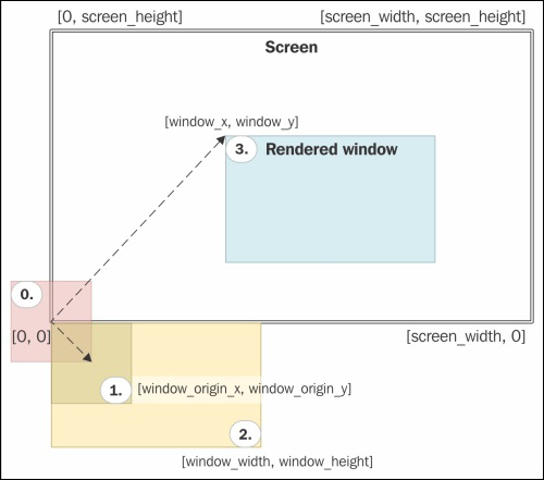
The first step consists of moving the basic rectangle to its origin point. This is followed by scaling, which will set the dimensions of the window. The final step is the translation to move the window to the desired position.