7
Architectures and Protocols for Next-Generation Cognitive Networking
R. Ganesh Babu1*, V. Amudha2 and P. Karthika3
1 Department of Electronics and Communication Engineering, SRM TRP Engineering College, Tamil Nadu, India
2 Department of Electronics and Communication Engineering, Saveetha School of Engineering, Tamil Nadu, India
3 Kalasalingam Academy of Research and Education, Tamil Nadu, India
Abstract
Cognitive Radio (CR) supports more software flexibility and affordability features than other radio classes. CR is a radio with intelligence for spectrum sensing, spectrum sharing, and spectrum management with self-aware capability. It can learn and sense the environment to detect the operating conditions and reconfigure its own characteristics to provide the best suitable conditions for secondary communication.The quality of transmission is based on their type of modulation, frequency, and power. If there is any interference occurring in the cognitive radio network, it can automatically adjust to provide the best suitable conditions for data rate, power, and frequency. The key advantage of the cognitive radio network is self-awareness. The process of dynamically accessing the unused spectral bands (spectrum holes/white spaces) is known as Dynamic Spectrum Access (DSA). Better spectrum communication of the xG network is maintained without spectrum space, by allowing CR to operate any one of the best available spectrum band. If primary communication occurs in channel sensing state, the occupied CR user should vacate the current position with informing the remaining CR users. The Occurrence of primary signal decision about time delay is less.
Keywords: Cognitive radio, Dynamic Spectrum Access (DSA), NeXt Generation (xG) network, spectrum sensing, spectrum sharing, spectrum management, self awareness
7.1 Introduction
The Dynamic Spectrum Access of NeXt Generation (xG) network architecture [1] can be classified into two main components, namely, the (1) primary network and (2) CR network (Figure 7.1).
7.1.1 Primary Network (Licensed Network)
The main network module comprises the primary user (licensed user) and primary base station (licensed base station). The main network is functioning on the primary user and primary base station to access a particular spectrum band. The primary network components consist of the primary user (licensed user) and primary base station (licensed base station). Primary user (licensed/noncognitive user): Primary users are users licensed to access a spectrum from the government, such as Jio, Vodafone, MTNL, Tata Docomo, and Airtel. An assured range of the spectrum band is permitted for access by primary users. Whole licensed users accessing facility is controlled by the primary base station. It cannot be affected by the actions from unlicensed users. Licensed users do not change with alteration for living with CR users and CR base stations over the spectrum band.

Figure 7.1 xG network/DSANs/CRAHN architecture.
Primary base station (licensed base station): The main network base station does not involve next-generation spectrum capability with secondary users. It may have additional functionality to ensure both CR protocols and legacy for licensed access of multiple secondary users.
7.1.2 CR Network (Unlicensed Network)
It is not licensed to access particular band frequencies in the spectrum. The secondary users, unlicensed base station (CR base station), and scheduling server are the main components of a secondary network.
Secondary user (unlicensed/cognitive Radio/xG user): A cognitive radio user does not specify spectrum communication. The secondary networks do not have license to access the spectrum bands. Hence, additional functionality to access the spectrum band.
Secondary base station (unlicensed base station): The secondary base station makes available single-hop access communication over a set of unlicensed spectrum bands in a CR user. From this linking, a secondary user is able to communicate over other networks.
Scheduling server (spectrum broker): It is an essential set-up object that has a major role in accessing the spectrum resource assets between different next-generation networks.
Unlicensed Network Access Types
The dynamic accessing unlicensed network depends on CR network access, CR ad hoc access, and primary network access.
- CR network access: Cognitive users able to access both primary and secondary spectral bands with the help of a secondary base station.
- CR ad hoc access: The ad hoc association on multiple CR users is performed at both primary and secondary spectral bands. Dynamically requests and accesses the available spectrum of PU. By accessing licensed spectrum band, additional functionalities are required.
- Primary network access: CR users able to access the licensed spectrum band through a primary base station.
CR Network Functions
The next-generation network is suitable for accessing licensed bands and unlicensed bands in a CR network.
- CR network on a licensed band: The specific spectrum bands can be accessed on the same location along with the CR network on the primary network (Figure 7.2). If primary users exist to access a certain spectrum band employed by secondary users, secondary users should shift unoccupied vacant spectrum positions immediately. The operation is called a spectrum handoff.
- CR network on an unlicensed band: All network activities have the same privileges to operate particular spectrum bands when there are no license owners (Figure 7.3). Multiple operators coexist with the same area in the spectrum portions.

Figure 7.2 CR network on a licensed band.
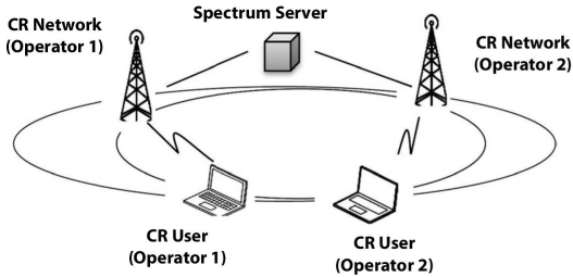
Figure 7.3 CR network on an unlicensed band.
7.2 Cognitive Radio Network Technologies and Applications
A software-defined radio (SDR) united with a clever system that has the ability of identifying locations, enhancing radio resources. and acquiring system enactment is called a cognitive radio (CR). Dillinger et al. [9] illustrate that SDR technology is feasible and controls congestion management and spectrum management. CR supports more software flexibility and affordability features than other radio classes. Software flexibility has to be adaptive and compassionate to a current scheme if new software is executed and software affordability is economical to support the present system. Wyglinski et al. [22] state that CR is a radio with intelligence for spectrum sensing, spectrum sharing, and spectrum management with self-aware capability. Celebi and Arslan [6] say that it can learn and sense the environment to detect the operating conditions and reconfigure its own characteristics to provide the best suitable conditions for secondary communication.
Hassim and Ghazali, [17] discussed that the quality of transmission is based on the type of modulation, frequency, and power. If there is any interference occurring in the cognitive radio network, it can automatically adjust to provide the best suitable conditions for data rate, power, and frequency. The key advantage of a cognitive radio network is self-awareness. The unemployed spectral bands accessing dynamically (spectrum holes/white spaces) are known as dynamic spectrum access (DSA). Kokar and Lechowicz [19] discussed that better spectrum communication of the CR network is maintained without spectrum space, by permitting CR to work any one of the finest unfilled spectrum band. In conventional radio, there is no ability to change the parameters dynamically and the spectrum band in response to environmental interferences.
7.2.1 Classes of CR
Arslan [4] presents a CR which is the advanced evolution of SDR technology. CR is programmed and configured dynamically. It can make link optimization decisions. Fette [11] describes that CR is equipped with more reconfigurable features than other radio classes. Table 7.1 shows the performance of different classes of radio property.
Haykin [18] illustrates that CR is implemented using ultra-wide-band (UWB) antennas (3.1 to 10.6 GHz) and spread over a wide frequency band for spectrum detecting and tunable/smart antennas and is used for communication. Mitola [20] describes that the cognitive radio system frequency bands are as follows:
Table 7.1 Advanced classes of radio properties.
| Radio property | Software capable radio | Software programmable radio | Software defined radio | Aware radio | Adaptive radio | Cognitive radio |
| Frequency hopping | X | X | X | X | X | X |
| Automatic link establishment (i.e., channel selection) | X | X | X | X | X | X |
| Programmable crypto | X | X | X | X | X | X |
| Networking capabilities | X | X | X | X | X | |
| Multiple waveform interoperability | X | X | X | X | X | |
| In-the-field upgradable | X | X | X | X | X | |
| Full software control of all signal processing, crypto, and networking functionality | X | * | * | * | ||
| QoS measuring/ channel state information gathering | X | X | X | |||
| Modification of radio parameters as function of sensor inputs | X | X | ||||
| Learning about environment | X | |||||
| Experimenting with different settings | X |
* The industry standards organizations are in the process of determining the details of what properties should be expected of aware, adaptive and CRs.
- UHF bands: 470-806 MHz used by broadcast television
- Cellular bands: 800/900 MHz, 1.8/1.9 GHz, 2.1 GHz, 2.3 GHz, and 2.5 GHz
- Immovable wireless bands: two-way broadband facility and are targeted near 2.5 and 3.5 GHz
- Ideal SDR device ability to reasonably contact three-octave bands from 0.4 to 0.96 GHz, from 1.3 to 2.5 GHz, and from 2.5 to 5.9 GHz
7.2.2 Next Generation (xG) of CR Applications
A CR network is best suitable for the ensuing applications to improving the detecting performance cooperatively with cognitive and non-cognitive users.
- Cooperative leased network: The main network is responsible for a leased network by authorizing adaptable access to its registered spectrum range with a third-party treaty without sacrificing the facility of the licensed user. Ex: Mobile Virtual Network Operator (MVNO).
- Cognitive mesh network: A wireless mesh network is offered with a high-speed Internet connection. However, with the increased network density, the network needs more capability to meet applications. The sensible CR technology gets into larger radio frequencies. Hence, CR networks with mesh networks situated in dense urban areas.
- Safety emergency network: In situations of natural disasters, it may lead to the destruction of the existing infrastructure. The emergency network deals with important information, where reliable communication is guaranteed with minimal delays. The CR network can access the existing spectrum by keeping priority communication and response time without requiring the infrastructure.
- Military network: It provide safeguard transfer information to the hostile environment with strong protection. Hence, it performs secured spectral band themselves.
- Cooperative dynamic spectrum access for IoT service: IoT-capable objects will be interconnected through wired and wireless communication technologies in the CR networks.
7.3 Cognitive Computing: Architecture, Technologies, and Intelligent Applications
7.3.1 CR Physical Architecture
Figure 7.4(a) shows the CR transceiver section components of RF front-end and baseband processing. The control bus is used every module to establish the time-varying RF environment by a reconfiguration process. Rondeau and Bostain [21] present that the received radio-frequency (RF) signal is amplified from the antenna; mixing and conversion of A/D by RF front-end and amplified signal is then down-converted/ up-converted to baseband for demodulation/modulation by baseband processing.
Figure 7.4(b) shows the RF front-end structure of a wideband antenna, a low-noise amplifier (LNA), a mixer, a voltage-controlled oscillator (VCO), a phase-locked loop (PLL), a channel selection filter, intermediate frequency (IF)/automatic gain control (AGC), and an analog-to-digital converter (ADC), Chaudhari, [7]. The received radio-frequency signal selects band-pass filter (BPF), followed by LNA. LNA is the amplified noise reduction of the desired signal. A mixer is used to mix with the received signal, and a local oscillating signal converts them to the IF range of the signal. VCO performs the specified voltage to mix the entering signal at the particular frequency. The selection of the channel is filtered to reject adjacent network channels and selects the desired response of the channel. AGC controls the constant amplifier output power level of the wide-band signal.

Figure 7.4 CR physical architecture: (a) CR transceiver and (b) RF front-end structure.
7.4 Functionalities of CR in NeXt Generation (xG) Networks
Biglieri et al. [5] present the enhancement of spectral efficiency in CR networks, cooperative features incorporated with spectrum sensing and spectrum sharing with each other. Figure 7.5 shows dynamic access of cooperative spectral functionalities, which are spectrum management, spectrum decision, spectrum mobility, user applications, transport, network, data link, and physical layer.

Figure 7.5 Communication functionalities of a CR network.
7.5 Spectrum Sensing
The unemployed spectral bands accessing dynamically (spectrum holes/ white spaces) and sharing spectral bands without harmful interference to other users are shown in Figure 7.6.
7.5.1 Spectrum Decision
The spectrum decision decides the characteristics of the spectrum, user requirement selection, and CR reconfiguration functions. The CR network adopts the finest suitable spectral band to improve the necessities of the overall spectrum quality of service (QoS) and capture the best obtainable spectral bands.
7.5.2 Spectrum Mobility
A transition of the better spectrum of the CR network is maintained by the seamless communication requirements.
Spectrum Sharing
Spectrum sharing is a facility to allow spectrum functionality resources with various secondary users (unauthorized users). The spectrum sharing access techniques in a CR network consists of underlay and overlay. In Figure 7.7(a), underlay process the simultaneous transmissions are allowed by authorized and unauthorized users as long as the noisiness at the PU is at a tolerable level.
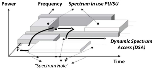
Figure 7.6 Spectrum hole concept.
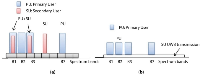
Figure 7.7 Spectrum sharing access techniques: (a) underlay and (b) overlay.
But in Figure 7.7(b), overlay process the cognitive devices overhear the knowledge of channel conditions, activity, signal codebooks, and messages of the non-cognitive radio users (primary users) and enhance the primary communication or avoid the interferences by the primary users.
7.5.3 CR Network Functions
Chen and Prasad [8] present a CR network function that varies according to licensed and unlicensed spectrum bands.
CR Network on an Authorized Band
Figure 7.8 shows that a CR network can communicate with the primary network for accessing the particular spectral band on the same location. Ekram and Bhargava [10] stated that PUs request for spectrum, xG users shift to the newly available spectrum band and vacate from the current spectrum band immediately; this is called a spectrum handoff.
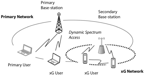
Figure 7.8 CR network accessing an authorized band.
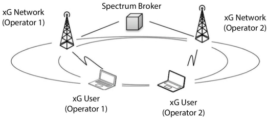
Figure 7.9 CR network accessing an unauthorized band.
CR Network on an Unauthorized Band
All network activities have the same privileges to operate particular spectrum bands when there are no license owners (Figure 7.9). Multiple operators coexist with the same area in the spectrum portions.
7.6 Cognitive Computing for Smart Communications
7.6.1 CR Technologies
The CR technology involves the Voice over Internet calls, video streaming, and data downloading (music, audio) for smart communications. Communications in a cognitive radio network are shown in Figure 7.10. These communications are defined based on their modulation, frequency, and power [12‒16]. Power is the important parameter in the mobile phones. Minimum power for transmission is achieved with a patch antenna with sectoring in an array fashion. The patch antenna covers 360 degrees of signal radiation, and it can transmit and receive. In this example, the network consists of two different Voice over Internet calls and they are differentiated by their modulation and frequency. Voice over Internet call 1 has low-bit-rate modulation, frequency of 5 GHz, and low power. Voice over Internet call 2 has medium-bit-rate modulation, frequency of 900 MHz, and low power. This is how the communication happens with the antenna.

Figure 7.10 Cognitive radio network.
Figure 7.11 shows that interference occurs in a cognitive radio environment. For example, let us consider interferers occurring in Voice over Internet call 2, video streaming, and data downloading. The video streaming, data downloading, and Voice over Internet call 2 operations are disturbed and interfered by any device or mobile phone. So it can affect the type of modulation, frequency range, and power level.
Figure 7.12 shows the self-adjusting of the dynamic cognizance radio network. The key advantages of a cognitive radio network are self-awareness and self-adjusting. Whenever interference is detected in a cognitive radio network, it can be rectified automatically. But in the conventional radio, there is no ability to change the dynamic parameter and spectrum band response to having an unacceptable level of interference for communicating. Similarly, the data download power is adjusted from medium to high power, and Voiceover Internet call bit rate modulation is adjusted from medium to low.

Figure 7.11 Interferers are detected in a CR network.
7.7 Spectrum Allocation in Cognitive Radio
There are wireless devices growing day by day utilizing the radio spectrum. The spectrum bands are fixed, but the accessing devices are growing rapidly. Hence, improving dynamic spectrum resources opportunistically through cognitive radio (CR). Cognitive radio is a radio with intelligence to assign a spectrum between primary and secondary users. Paid users with a license to use the spectrum are called primary users; the other type without a license is known as secondary users. Allocation of channels in a fixed spectrum band is done by many methods such as cooperative and noncooperative ones. Artificial intelligence techniques play a major role in spectrum allocation, such as neural networks, fuzzy logic, ant colonies, particle swarm algorithms, genetic algorithm, and deep learning. In this section, the idea of dynamic spectrum allocation (DSA) method using genetic algorithm is discussed [3]. This spectrum management selection is allotted in an overlay manner; i.e., secondary users are allotted band access in the nonappearance of primary users on the condition that the secondary users switch to a free band whenever a primary user enters the band. To proceed with this method, the RF parameters of primary and secondary users must be known. In genetic algorithm, the RF parameters of the channels are represented in the form of chromosomes.

Figure 7.12 A CR network self-adjusts its characteristics.
Genetic algorithm is a biological evolutionary algorithm based on chromosomes and genes. The best genes in each chromosome can be selected, and these will be overlapped by crossover and mutation processes. The main advantage of GA is its flexibility and random nature. Unlike HMM, it does not need to allot a spectrum by any channel prediction state. So the trained set of chromosomes is available by the given input algorithm. A genetic-algorithm-based chromosome consists of genes; here the genes are the parameters of the CR network, i.e., modulation, power, frequency, and BER. The decision-making process is considered by each gene. The genes and their ranges for the operation of cognitive radio are assigned as frequency range from 40 MHz to 910 MHz, the power is -90 to -40 dBm, and the bit error rate is 10-9 to 10-1 (Table 7.2). The modulation techniques used are BPSK, QPSK, 8QAM, and 16QAM. Each gene value is important to decide its primary characteristics or secondary characteristics.
For the frequency gene, the total bandwidth is 800 MHz and each channel bandwidth B (channel) = 8 MHz is used to transmit and receive for a particular CR network. The frequency band considered for this research would range from 40 to 840 MHz with a step size = 8 MHz; each band is assigned to a decimal number. For example, 40-48 is assigned a decimal value of “1,” 49-56 is assigned to “2,” and so on up to 832-840, which is assigned to “100,” as shown in Table 7.3.
Compared to all genes in the chromosome, the important parameter is the power gene. The range of power values specified in IEEE 802.22 varies from -90 dBm to -40 dBm. The power gene is considered the standard values from 90 dBm to -40 dBm with a step size of 1 dBm is characterized in Table 7.4. Power is an important parameter for the detection of the presence of the primary node. Because if the power is less, it indicates the absence of the primary node and the secondary node can start transmission.
Another parameter is the bit error rate (BER), defined as ratio of erroneous bits to the total transmitted bits. BER may vary depending upon certain service applications. The bit error rates can be reduced by either coding schemes or the use of certain modulation at the receiver and transmitter. One more way to reduce the bit error rates is to increase the transmission power of the device that is limited by FCC. Here the bit error rates ranges between 10-1 and 10-9 with a step size of 10-1. Each value is assigned to a decimal number. For example, 10-1 is assigned to “1” and similarly 10-9 is assigned to “9” in Table 7.5.
Table 7.2 Selected genes and their ranges.
| Gene parameter | Values |
| Frequency (MHz) | 40 to 910 |
| Power (dBm) | -90 to -40 |
| BER | 10-1 to 10-9 |
| Modulation | BPSK, QPSK, 8-QAM, 16-QAM |
Table 7.3 Frequency gene representation.
| Decimal value | 1 | 2 | ... | 100 |
| Frequency band MHz | 40-48 | 48-56 | 832-840 |
Table 7.4 Power gene representation.
| Decimal value | 1 | 2 | .... | 50 |
| Power dBm | -90 | -89 | ... | -40 |
The last gene considered is the type of modulation used for transmission and reception. Here four modulation schemes are considered. These are binary phase shift keying (BPSK), quadrature phase shift keying (QPSK), quadrature amplitude modulation (8QAM), and 16QAM. Each modulation scheme is assigned to a decimal number from “1” to “4” as shown in Table 7.6.
The four genes, as discussed above, all together define the structure of the CR channel chromosome. The arrangement of all genes in the chromosome structure is shown in Table 7.7.
The primary chromosomes is considered the value of 20 with high-power and low-BER conditions. Low-power and high-BER conditions are assumed to characterize the presence of secondary chromosomes; with this characterization, a set of 20 secondary chromosomes is considered. The assumed conditions are represented in Table 7.8.
Table 7.5 BER gene representation.
| Decimal value | 1 | 2 | ... | 9 |
| BER | 10-1 | 10-2 | ... | 10-9 |
Table 7.6 Modulation gene representation.
| Decimal value | 1 | 2 | 3 | 4 |
| Mod. | BPSK | QPSK | 8QAM | 16QAM |
Table 7.7 Chromosome structure.
| Order | 1 | 2 | 3 | 4 |
| Gene | Frequency | Power | BER | Mod |
Table 7.8 Assumed conditions.
| Parameters | Primary | Secondary |
| Power dBm | -60 to -40 | -90 to -70 |
| BER | 10-9 to 10-6 | 10-4 to 10-1 |
| Mod. & freq. | Fixed | Fixed |
The set of chromosomes will be selected, and the fitness value will be calculated. Depending upon the fitness value, a conclusion will be made to decide to continue or to do crossover and mutation. Finally, the iteration is stopped after a number and the chromosome values are checked to occupy the whole spectrum or to vacate by the secondary node. It is observed that best fitness higher values will result in correct classification.
7.8 Cooperative and Cognitive Network
Cooperative cognitive network is capable of mitigating the uncertainty of noise power and the effect of fading and shadowing by providing spatial diversity [2]. The detection in a cognitive radio spectrum, the spectrum sensing time required to successfully detect a PU, is inversely proportional to the PU’s signal strength. When the PU operates in a low-SNR region, the effective transmission time of a CR system with a fixed transmission window can be extremely short for the CR system to fully utilize the spectrum. The performance of various cooperative spectrum-sensing comparison techniques is discussed in Table 7.9.
The techniques are (see Figure 7.13)
- Cooperative centralized coordinated
- Cooperative decentralized (distributed) coordinated
- Cooperative decentralized (distributed) uncoordinated
7.8.1 Cooperative Centralized Coordinated
In a cluster based cognitive radio network, the wideband spectra could share some common spectral components; such a data fusion center based cooperative wideband sensing technique will lead to a heavy data transmission burden in the common control channels (see Figure 7.14(a)).
Table 7.9 Comparison of cooperative wideband spectrum-sensing algorithms.
| Cooperative sensing algorithms | Advantages | Disadvantages |
| Centralized coordinated |
|
|
|
||
|
||
|
||
| Decentralized (distributed) coordinated |
|
|
|
||
|
||
|
||
|
||
| Decentralized (distributed) uncoordinated |
|
|
|
||
|
||
|
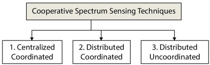
Figure 7.13 A CR network self-adjusts its characteristics.
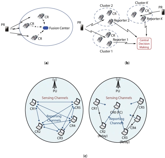
Figure 7.14 (a) Cooperative centralized technique. (b) Cooperative centralized decision fusion technique. (c) Cooperative decentralized (distributed) coordinated and uncoordinated.
An alternative is to develop a decision fusion central based cooperative wideband sensing technique if each cognitive radio is able to detect wideband spectrum independently (see Figure 7.14(b)).
7.8.2 Cooperative Decentralized (Distributed) Coordinated and Uncoordinated
A cognitive radio network accessing spectrum resources without required controller unit. Each cognitive user collect information and coordinate with each other which means individualistically to detect the channel by CR users. If primary communication occurs in channel sensing state, the occupied CR user should vacate the current position without informing the remaining CR users (Figure 7.14(c)).
References
- 1. Akyildiz, I.F., Lee, W.-Y., Vuran, M.C., Mohanty, S., NeXt generation/dynamic spectrum access/cognitive radio wireless networks: A survey. Comp. Netw. Elsevier, 50, 2127–2159, 2006.
- 2. Akyildiz, I.F., Lo, B.F., Balakrishnan, R., Cooperative spectrum sensing in cognitive radio networks: A survey. Phys. Commun., 4, 40–62, 2011.
- 3. Amudha, V., Ramesh, G.P., Dynamic spectrum allocation for cognitive radio using genetic algorithm. Int. J. Tech. Eng. Sci., 1, 1092–1097, 2013.
- 4. Arslan, H., Cognitive Radio, Software Defined Radio, and Adaptive Wireless Systems, Springer, Netherlands, 2007.
- 5. Biglieri, E., Goldsmith, A.J., Greenstein, L.J., Mandayam, N.B., Poor, H.V., Principles of Cognitive Radio, Cambridge University Press, USA, 2013.
- 6. Celebi, H. and Arslan, H., Enabling Location and Environment Awareness in Cognitive Radios. Comp. Commun. Elsevier, 31, 1114–1125, 2008.
- 7. Chaudhari, S., Spectrum sensing for cognitive radios: Algorithms, performance, and limitations, Schools of Electrical Engineering, Helsinki, Finland, 2012.
- 8. Chen, K.-C. and Prasad, R., Cognitive Radio Networks, John Wiley & Sons, Ltd, Chichester, UK, 2009.
- 9. Dillinger, M., Madani, K., Alonistioti, N., Software Defined Radio: Architectures, Systems and Functions, John Wiley, USA, 2003.
- 10. Ekram, H. and Bhargava, V.K., Cognitive Wireless Communications Networks, Springer Science & Business Media, Springer USA, 2007.
- 11. Fette, B.A., Cognitive Radio Technology, Elsevier, UK, 2009.
- 12. Ganesh Babu, R. and Amudha, V., Allow an Useful Interference of Authenticated Secondary User in Cognitive Radio Networks. Int. J. Pur. Appl. Math., 119, 3341–3354, 2018.
- 13. Ganesh Babu, R. and Amudha, V., Cluster Technique Based Channel Sensing in Cognitive Radio Networks. Int. J. Con. Theor. Appl., 9, 207–213, 2016.
- 14. Ganesh Babu, R. and Amudha, V., Comparative Analysis of Distributive Firefly Optimized Spectrum Sensing Clustering Techniques in Cognitive Radio Networks. J. Adv. Res. Dyn. Cont. Syst., 10, 1364–1373, 2018.
- 15. Ganesh Babu, R. and Amudha, V., Comparative Analysis of Distributive Optimized Clustering Techniques in Cognitive Radio Networks, proce. 1st Int. Conf. Emerg. Techno. Dat. Mini. Inform. Secu., (IEMIS) in association with Springer Advances in Intelligent Systems and Computing Series, February 23-25, 2018.
- 16. Ganesh Babu, R. and Amudha, V., Dynamic Spectrum Access Techniques in Cognitive Radio Networks, proce. 4th Int. Conf. Rec. Tren. Comp. Sci. Engg., (ICRTCSE) in association with Elsevier-Procedia Computer Science, April 29-30, 2016.
- 17. Hassim, Y.M.M. and Ghazali, R., Improving Functional Link Neural Network Learning Scheme for Mammographic Classification, Springer, Cham, 2016.
- 18. Haykin, S., Cognitive Radio: Brain-Empowered Wireless Communications. IEEE J. Sel. Area. Commun., 23, 201–220, 2005.
- 19. Kokar, M.M. and Lechowicz, L., Cognitive Radio Interoperability through Waveform Reconfiguration, Artech House, Norwood, 2016.
- 20. Mitola, J., Software Radio Architecture: Object-Oriented Approaches to Wireless System Engineering, John Wiley & Sons Ltd, USA, 2000.
- 21. Rondeau, T.W. and Bostain, C.W., Artificial Intelligence in Wireless Communication, Artech House, USA, 2009.
- 22. Wyglinski, A.M., Nekovee, M., Hou, Y.T., Cognitive Radio Communication and Networks, Elsevier, USA, 2010.
Note
- * Corresponding author: [email protected]