
19. Logical Network Topological Nodes
19.1 Introduction
This chapter covers network topological nodes. We won’t get into specific network hardware components such as routers and switches but will focus on the parts more relevant to designing and architecting a hearty application layer.
19.2 Network Diagrams
Network diagrams are a useful way to articulate an architectural design to colleagues. Being able to sketch components on the board allows you to summarize a complicated network clearly, concisely, and efficiently.
Several applications support drawing network diagrams. There are lots of flavors of edges and nodes, but they share commonalities. For the sake of this chapter, we’ll choose a few icons necessary to represent the components we’ll be discussing. Google Drive makes many icons available using the drawing dialog.
Hosts, compute instances, and worker machines are all terms referring to a computer on a network. They can host server applications, implement mapreduce, host daemonized processes like crond, or host a queue listener such as an nsq or a kafka client as well as any number of other tasks. We’ll represent these with the icon shown in Figure 19.1, where “Hostname” represents the name of the host in the network.

Figure 19.1 A common representation of a single host computer in a network
The Internet is usually represented with a cloud icon, as shown in Figure 19.2. It represents any type of possible traffic. This has a number of implications. First, any sort of request could come through. If there are types of traffic you would like to accept or reject, the Internet icon serves as a reminder that input should be filtered to only the sort of traffic desired. Further, it comes with the implication that potentially malicious traffic could be encountered, so inputs should be sanitized. These are two basic building blocks and the minimum required for a complete public-facing application (though the application wouldn’t be terribly resilient). Let’s get into some components that offer more robustness.

Figure 19.2 A common representation of the Internet
19.3 Load Balancing
Earlier we discussed using load balancers for the purpose of redundancy and distributing load to hosts of heavily used applications. The case we described earlier was for load balancing requests to an API. Figure 19.3 illustrates a simple network.
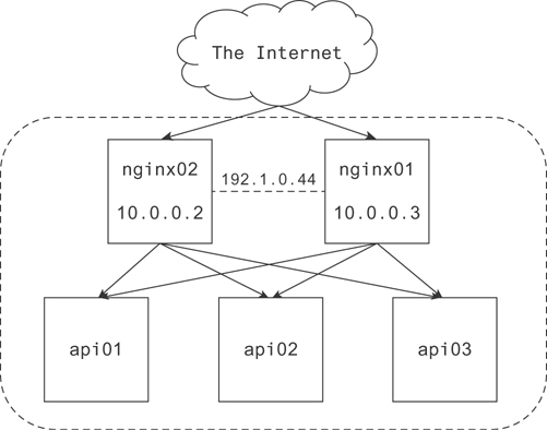
Figure 19.3 A representation of a simple network
There are several things to note here. First, the border around the nginx and api nodes indicates they are on the same network or behind the same gateway, which is the door to the Internet. The gateway is not pictured in Figure 19.3 since it’s out of the scope of our discussion. For our purposes, you can consider this boundary a convenient way to group nodes in your network.
Next, you should note there are two nginx hosts receiving requests from the Internet. Each of these has its own IP, but they also have a virtual IP, which is shared between them by CARP. This allows one to take over for the other in the event there is a node failure.
Finally, there are three api nodes, and each can receive requests from each nginx node. These are drawn as a full directional mesh, but it’s worth noting a lot of people prefer to draw an API layer to cut down on busy details like lots of arrows.
Most cloud providers make a reliable load balancer available to you. They take care of these little details so you don’t have to. It is still a good idea to know how to do them yourself.
There are a few great use cases for load balancers. The most common is the one pictured in Figure 19.3. A second one, though, is as a means of implementing multitenancy. Many applications are single-threaded (Python and Redis, for example). To make the most use of the CPU cores on larger machines, it’s common to run several of these processes at once, each listening on a different port.
Figure 19.4 shows how you might diagram multitenancy on a single API node.
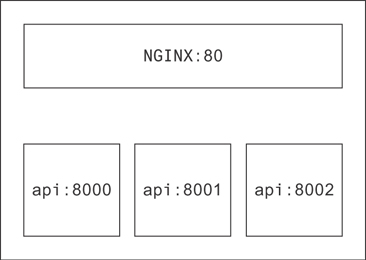
Figure 19.4 Multitenancy pictured on an API node
The colon indicates what port each process is listening to on that host. Here it’s understood from the context that nginx is routing requests to/from the API processes on this machine. You could make it more explicit, though, by drawing arrows.
19.4 Caches
Caches serve a few common purposes. There are many types of caches and many ways to use each one. We’ll discuss a few next.
19.4.1 Application-Level Caching
What makes a cache so fast? There is a short answer: it usually stores all your data in RAM. RAM is fast!
Caching in the application is appealing sometimes, especially when the application is small. In general, though, if you wanted to speak strictly, this violates the separation of concerns between processes. You should have one process for caching and another for handling requests. The 12-factor standard for application development supports this with the assertion that state should not be maintained in a 12-factor application. Something sitting in the cache represents the state of that cached object at that time.
If you insist on application-level caching, be aware of some important caveats: processes don’t typically share memory. This means a cache on one process will not be visible to another; hence, invalidating an object on write in that cache will not invalidate it in other application caches. Effective caching requires a memory management/eviction strategy. If you don’t have a process in place for removing elements from the cache, you have effectively created a memory leak. Each time your application reboots (normal deploys, for example), the origin of your cached resource will see burst traffic. This can become a bigger concern as your application becomes more popular. Shared resources between requests, especially those that require authentication, should be a big red flag. Making it possible to share state across requests opens your application to many dangers, including accidentally revealing an access token (or worse) for one user to another user.
Now, if you still insist on application-level caching, allow us to give two use cases, one of which is totally fine and another that can cause major headaches.
19.4.1.1 The Case for Static Content
The first case is when you have only a few processes that receive API requests, which commonly need to translate IDs into static content. Let’s imagine you’ve built a recommender system that maintains a mapping of IDs to content features it takes into account. When the recommender has generated some optimal results for a user, it ends up with a list of these content IDs. Now it’s faced with the task of sending the client back the content representation itself.
This is typically done by making a database call for the content through another API, joining those results to the recommender results, and sending the whole package back to the user. If you use an application cache, you can store the content mapped to each ID and avoid ever having to make the request. This would be a big time-saver. Since the content is pretty static, it’s no big deal if one application’s version goes stale for a while.
You might notice in this case content that is currently popular stays popular for a while and then makes way for new popular content. In this case, a “least recently used” eviction policy would be pretty appropriate. As content becomes less often used, it will fall off the end of the cache. This ensures the number of external API calls for the static content is at a minimum.
19.4.1.2 The Case to Avoid Locally Caching Sensitive Information
Let’s say you have a complicated process of checking a user ID against a number of subroutines to validate their eligibility to use a particular feature. Since each of these are well-encapsulated and all of them require the complete user record, it might be appealing to store the user account information in the application cache. You might think that if you encapsulate all the cached data per request, other users won’t be able to see it since it will be gone after the current user has been served.
This seems sound at a glance. However, it assumes there is no shared state between requests. In app servers that allow for coroutines and other asynchronous code, these objects can still persist as other requests are being served since one request can be paused while waiting on IO and another request resumed. If, in your subroutines, you use a globally defined method to reference the request, you will inevitably end up with the wrong user information in the request.
19.4.2 Cache Services
The most common of these is memcached and Redis. Redis seems to be eclipsing memcached at the moment for a couple reasons. It offers types, and it happens to be faster when it’s implemented right (using multitenancy or multiple master nodes).
In Figure 19.5 you can find a typical interaction between the API layer, the application cache, and the database. The cache usually serves two purposes in this context. The first is a response cache. The second is an object cache.
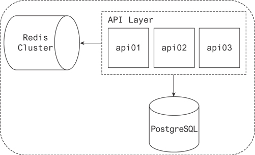
Figure 19.5 An API with a caching layer backed by a database
Caching responses that can be reused allows the API to save a ton of time. What might be a series of template computations and API and database calls turns into an O(1) lookup and a simple transfer of data.
Object caches allow the API to say “Have I requested this recently?” and in the case it has, it says, “Okay, I’ll take it from the cache instead of the database.”
19.4.3 Write-Through Caches
The process of aggregating statistics can be heavy. Further, if you have many applications doing the aggregation, they often need some form of concurrency control. There are a few ways to achieve this. A cache is one possible solution.
One of the simplest ways to manage applications that are aggregating concurrently is to use the incr/decr methods made available by Redis. If the statistics are not business critical in the sense that they absolutely cannot disappear, a cache is a good choice to aggregate them and serve them from.
When you do need that persistence layer, a database will usually do. If the rate of incoming updates becomes too high, though, you may consider techniques for batching them. There are two approaches to using a write-through cache to do this that come to mind.
The first involves a write-through cache in the application. As your taskworker receives messages from your queueing system, it saves them for a moment. If it encounters more than one update for a single record, it combines them. When those updates are successfully communicated to the database, the taskworker signals it has completed the update.
The second approach to managing a write-through cache takes into account that a user will continue sending events related to their session until the session times out. Imagine taskworkers each register a user session in the cache upon receipt of the first message from a given user. If the session already exists, the taskworker can increment its reference count. If a taskworker already has an active session (meaning they have incremented the session by 1), each additional message for the session is simply written to the cache as it arrives. This allows you to track how many taskworkers have an active reference to a given session at any time during the session. When that initial create session or increment operation occurs, a timer can be started on the taskworker. A new message coming in extends the time. No messages coming in allows the clock to run out. When the clock runs out for a given taskworker, it decrements the reference count to the session. The last taskworker to decrement its reference count deletes the session from the cache and writes the aggregate data to the database.
19.5 Databases
There are so many databases out there! Depending on which one you’re running, there are a handful of standard approaches to ensuring the resilience of your data. We’ll go through a few of them here.
19.5.1 Primary and Replica
Lots of databases use this approach to replication. MySQL, PostgreSQL, Redis, and MongoDB are a few. Figure 19.6 pictures the standard interactions between an API and a primary-replica database configuration.
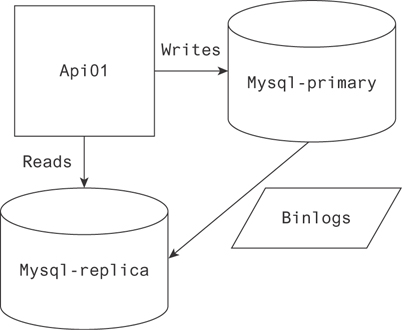
Figure 19.6 An API implementing reads from a replica and writes to a primary node
The gist of it is that only one node accepts database writes. That node is responsible for communicating the data it receives to the replica, secondary, or slave as you prefer. Usually this is done by transferring a binary log of the writes to the secondary node. This allows the two to stay in sync for the most part.
Replica lag is the phenomenon associated with the latency between the primary and replica nodes. It takes a bit of time to sync the binlogs from the primary to the replica, so data on the replica isn’t immediately available after writing to the master. Common replica lag is in milliseconds.
This is an important caveat to take into account. If you need a strong guarantee the value you’re reading is completely up-to-date, you will have to do that read on the primary node. A common method for scaling at the early stage, though, is reading from the replica wherever possible. This phenomenon is what decides what reads can be done where.
Naturally with this configuration your writes go to one node, and to the best of your ability you send the reads to another. If your application is more read-heavy, you can keep adding replica nodes with little consequence in terms of syncing binlogs. But what if it’s more write-heavy?
19.5.2 Multimaster
There are a couple cases where it makes sense to use multiple master nodes. One case is to scale database writes. There are two approaches to this. The first is the more standard approach, using two master nodes and backing up to the same slave. Each master will have a partition of the data, but the replica will have all of it. The second approach is to route objects in the application to a master based on some characteristic of the object. With this approach each master is typically backed up to its own replica (Figure 19.7).
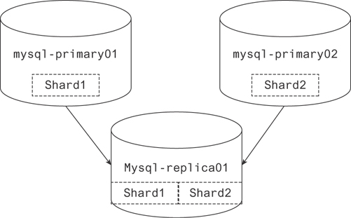
Figure 19.7 Two primary nodes in a multimaster configuration writing to the same replica
But it simplifies reading from your database to have them write to the same replica.
In the first approach, clients can choose what primary node to write to at random and distribute objects pretty effectively. There are some important caveats to this approach. As long as reads are sent to the replica, it’s simple to return a complete result. If reads are sent to either primary node, the results will be missing the data stored on the parallel primary node. The second important caveat involves avoiding conflicting data on the replica. If your keys are set to auto-increment on both master nodes, two objects sent to the replica can and will have matching primary keys, which violates the unique constraint of a primary key. A simple solution is to increment on both masters by 2 and give one an offset of 1.
19.5.3 A/B Replication
Figure 19.8 shows two primaries writing to a single replica; this is the simplest case of A/B replication. In this scenario, data is conceptually partitioned into separate distinct shards. It is then replicated at least once for each shard.
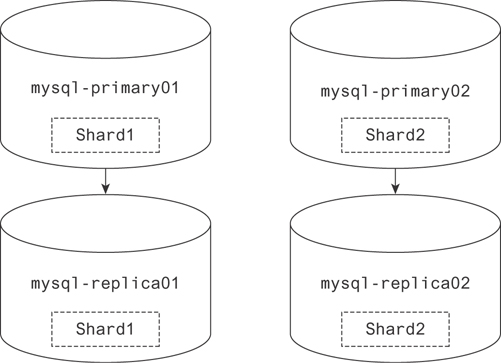
Figure 19.8 Two primary nodes in a multimaster configuration writing to their own replicas
This approach makes a lot of sense in terms of storage. If you have a 100-node cluster, for example, each containing a complete record of your database, that is a lot of space! By copying each shard twice, you save a lot of room. Many databases take this approach to replicating data. Elasticsearch, MongoDB, and Cassandra are a few.
Figure 19.9 shows a slightly more complicated approach to sharding. Elasticsearch manages its data in this way. If one node disappears for whatever reason, it begins copying the missing copy of whichever shards were on that node to another available host. If two nodes disappear with the only copy of a shard, that data is lost forever.
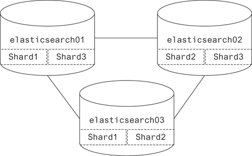
Figure 19.9 A more complete example of a basic sharded database
19.6 Queues
There are many use cases for queues. In essence, they allow for asynchronous event handling. This enables parallel execution as well as the management of “who does what.” In this section, we will talk about scheduling dependent tasks, remote procedure calls, and API buffering.
19.6.1 Task Scheduling and Parallelization
Sometimes it’s necessary to run tasks every so often. When the task is a one-off, it’s simple. You can just run it as a crond task. As infrastructure becomes more complex, though, and as one-off scheduled tasks become to depend on each other, it becomes more necessary to use a queue.
Why might you use a queue instead of just running the tasks synchronously, one after the other? I’m glad you asked. There is a single case where it makes sense to do that. That is in the case your dependency has no branches, as shown in Figure 19.10. We start with the event, A. The result of A is sent to process B, and the result of B is sent to process C. Executing this on one node would have about the same benefit as using a queue since they have to execute serially.
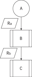
Figure 19.10 Cascading scheduled tasks, originating at A and ending at C
When you have multiple tasks dependent on a single result, the case for a queue becomes clear. By having each dependent process subscribe to the queue for the process on which it depends, they can all be relayed the result to process independently. Further, if there are tasks dependent on them, they can be triggered in the same way. In Figure 19.11, B and C both depend on the result of A. D, E, and F depend on the result of B, while G depends on the result of C.
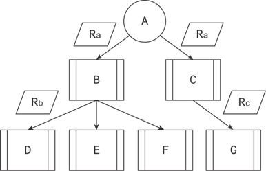
Figure 19.11 Cascading scheduled tasks, forming a complex tree of tasks
The benefit of this approach is parallelization. Assuming there exist four processes to do the execution, D, E, F, and G can all be executed at the same time. Distributing workload in this way ensures computational resources are used as efficiently as possible since those processes that are not busy are listening for work to do.
19.6.2 Asynchronous Process Execution
When a user-facing client sends a request, it’s usually desirable for them to see an immediate result. If there’s a lot of work to do, it makes sense to respond to the client and kick off a job to do that work asynchronously.
One great example of this is when a user signs up to a social network and you want to find all their friends on that network and make it available for them to interact with those friends. In this case, you’ll send an event indicating contacts should be synced and then allow the user to proceed to the next dialog.
This could look something like what is pictured in Figure 19.12.
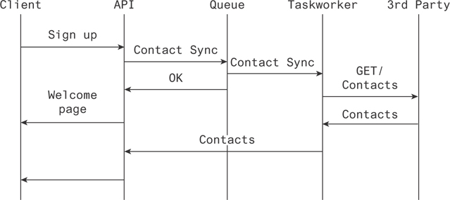
Figure 19.12 Tasks firing outside the critical path of the user to provide a seamless experience
In other words, the client signs up for a service to the API. The API sends a message to a queue indicating contacts should be synced for that user. A taskworker, listening to that queue, receives the message and queries a third party. It then relays those results to the API upon receipt, making them available to the user.
19.6.3 API Buffering
Sometimes applications can see burst traffic far out of bounds from what is typical for the application. When this happens, the application has to either scale or space out requests to a level that is acceptable. Concretely, if an application designed to handle 100 requests per second receives 500 requests in a second, it could find itself inundated to the extent that application errors result or it times out. A five-second delay on a request isn’t fatal from a user perspective; it’s a degradation for sure but not a failure.
Queues provide a great way to space out incoming requests to a rate the API can handle. If writes are written to a horizontally scaled queue, they can be inserted as the API is available. Taskworkers listen for those writes and execute them just as quickly as they can, alerting the client to their completion through push or some other server client protocol.
19.7 Conclusion
When you understand the building blocks of a distributed system, the possibilities become endless. You can piece these together in complex configurations to suit a multitude of needs. Computing on the fly, precaching, task scheduling, parallelization, and many other implementations are possible with the elements discussed in this chapter.
As you build out your architectural designs, diagramming and referring to those diagrams during discussions makes for well-informed, well-motivated conversations. There are many flavors of these diagrams, but the most important thing to remember is consistency.