Lesson 3. Colors, Gradients, and Styles
We live in a full-color world. Color adds interest to artwork, whether printed or displayed on a web page. Color provides visual clues about objects around us: when we see a red sign, we know to stop; when we see a green light, we know to go. The color you add to the object you draw in this lesson may be enough to suggest a brand name, even though you don’t add the company name to the product.
We see color when a light source reflects on an object. Our eyes receive the reflected light and transmit a message to our brain, causing us to see a particular color. How you reproduce the color on your computer depends on the way you want to use the drawing. Are you creating an image to be used on the web? Or do you want to include the image in a page-layout program or print directly from FreeHand? If you want to print, do you want to print on a color printer or to send your project to a commercial printer? Your answers to these questions determine how you create colors in FreeHand. Once you create colors for a particular output device, however, you can easily convert the colors for other uses.
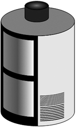
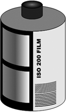
To create the film canister for this lesson, you will split an ellipse and then use a portion of the ellipse for one side of the canister. You then will make a copy of that shape and flip it for the other side. You will add colors and a gradient fill to create the illusion of a 3D object.
In this lesson, you will mix a color, save the color, and apply it to an object. Before you do that though, you need to draw the object you want colored. First, you will create a film canister to be used in an advertisement and on a web page. You will draw half of the canister and then use tools to make a copy and reflect the copy for the other half. Once the film canister is almost complete, you will add some color and a gradient fill to make the cylindrical canister look more realistic. In the next lesson, you will draw a strip of film and use the 3D Rotation tool to make the film appear as if it is jutting out from the canister. In another lesson, you will animate the film moving out from the canister.
WHAT YOU WILL LEARN
In this lesson, you will:
• Learn about splitting and joining paths
• Learn to reflect, scale, and rotate objects
• Use the Mirror tool
• Use the transformation handles to scale an object
• Use the Color Mixer and Tints panels to create colors
• Add colors to the Swatches panel
• Create gradients and add them to objects
• Save graphic properties on the Styles panel
• Use the Subselect tool
• Use the Arc tool
APPROXIMATE TIME
This lesson takes approximately 3 hours to complete.
LESSON FILES
Media Files:
None
Starting Files:
None
Completed Projects:
Lesson03Completedfilm_canister.fh11
Using Split and Join
In Lesson 1, you were introduced to the concepts of points and paths. When you used the Knife tool to cut the polygon, you split the closed path of the polygon, creating two open paths. If a point already exists on a path, you can use the Split command to create new paths. Of course, you could also use the Knife tool to cut the path, but you may have difficulty cutting exactly on the point. Using the Split command makes the cut more quickly and more precisely.
An object must be a closed path if you want to add a fill color. Once you split an object, you may then want to move the points to change the shape. Then you can use the Join command to combine two open paths or to add a line connecting two selected points.
1) Create a new document and save it as film_canister.fh11 in your Projects folder. Turn on the page rulers if they are not visible. Drag horizontal and vertical guides to the middle of the page.
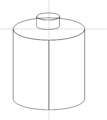
The film canister consists of an ellipse at the top for the end cap, a colored right side, and a black left side. Since the left and right sides are identical, you will draw one side, make a copy of it, and then reflect the copy for the other side. The guides will help you create one side and the reflected copy.
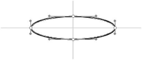
2) Select the Ellipse tool and draw a horizontal ellipse from the center of the intersection of the guides. Make the ellipse approximately 100 x 30 pixels.
In Lesson 1, you learned to hold down Alt (Windows) or Option (Mac OS) to draw from the center of a rectangle or ellipse. You will use the ellipse you just created to draw the base of the canister and then make a copy of the ellipse to draw the end cap of the canister.
To achieve the perspective of a three-dimensional object, do not make the ellipse too tall vertically. Move the mouse up or down to change the height. If you do not like the drawn figure, delete it and draw it again. You can also resize it with the Pointer tool by dragging one of the handles; however, if you do this, you may move the center away from the intersection of the guides.
3) Choose Edit > Copy and then choose Edit > Paste. Move the copy to the pasteboard.
You’ve moved your drawing to the pasteboard for safekeeping. You will use this copy of the ellipse as the end cap in later steps.
4) Select the original ellipse and then choose Modify > Ungroup.
The basic shapes you draw with the Ellipse and Rectangle tools are grouped as one object by default. Since they are grouped, you see the four corner handles of the bounding box of the selected object instead of individual points. When you ungroup the object, you see the points on the object that control its shape. You want to split the ellipse at those four points, breaking the ellipse into four separate pieces.
5) Using the Pointer tool, drag around the entire ellipse with the selection rectangle.
All points on the ellipse should now be selected. Selected points have hollow squares instead of solid squares. You should also see handles jutting out from the selected points. You’ll learn more about these handles in a later lesson.
Note
When you drag the Pointer tool on the page, you see a dashed rectangle. All objects within that rectangle, called the selection rectangle, are selected when you release the mouse button. In later lessons, you will use the selection rectangle to select multiple items on the page.
6) Choose Modify > Split.
The ellipse is split into four objects. You want to use the lower left arc to draw the left half of the canister base. Look at the Object panel. It should show that you have four objects selected.
7) Press Tab to deselect the four sections of the ellipse. Using the Pointer tool, select and then delete the top two sections and the lower right section, leaving only the lower left arc.
Another method is to hold down Shift and click the lower left arc with the Pointer tool. This deselects only the lower left arc. You can then delete the three remaining selected arcs. The Shift key works as a toggle, adding to or subtracting from the selection.
8) Hold down Alt (Windows) or Option (Mac OS) and drag down to create a copy of the arc. Add Shift as you drag to prevent the copy from moving left or right.
The copy of the arc is the bottom section of the left side of the canister. The film canister is tall and skinny. Drag the copy down approximately three times the width of the arc. To complete the left side of the canister, you just need to connect the two arcs with two vertical lines. The quickest way to do this is to join the two arcs, which you will do in the next step.
9) Hold down Shift and select the top arc with the Pointer tool; then choose Modify > Join.
A vertical line is drawn, connecting the two arcs on one side.
Note
The Join command does not always work as expected. If you do not get a connecting line as shown, draw a vertical line with the Line tool between the arcs and then use the Join command to connect the line to the two arcs.
10) Click Closed in the Object panel.
FreeHand draws a line connecting the other two points in the arcs, creating a closed path.
Reflecting Objects
Reflecting flips a selected object or objects about a specific axis. Often you will want mirror images of the objects you draw. For example, the shape you just created is the left side of the canister. The other side is the same shape flipped to the right. FreeHand provides several ways to reflect objects: using the Reflect tool, the Reflect panel, and the Mirror tool. The Reflect panel and the Reflect tool accomplish the same tasks. Depending on your preferences, you may find one easier to use than the other. For example, with the Reflect tool, you see the results on the screen as you use the tool. With the Reflect panel, you enter the axis angle you want to use for the reflection.
You will now make a copy of the shape you just created and then use the Reflect tool to flip it about the vertical axis. Later in this lesson, you will use the Reflect panel and the Mirror tool.
1) Select the shape and then choose Edit > Clone.
Cloning an object makes an exact copy and places it directly on top of the original. The clone is currently selected.
2) Hold down the mouse on the Scale tool and choose the Reflect tool from the tool group.
Three other tools are grouped with the Scale tool: the Rotate tool, the Reflect tool, and the Skew tool. Selecting any of these tools changes the cursor to a star.
The Scale tool allows you to scale a selected object by dragging. If you hold down Shift as you drag, the object is scaled proportionally. You will scale one of your objects later in this lesson.
The Rotate tool allows you to rotate a selected object by dragging. You will rotate an object later in this lesson.
The Skew tool allows you to skew (or distort) a selected object by dragging.
3) Move the pointer over the right side of the object. Hold down Shift and drag down.
The clone of the shape flips about the vertical axis. Holding down Shift as you drag constrains the reflected angle to 90-degrees. Release the mouse button when you see the mirror image of the shape.
Note
If you are confused about the concept of dragging down to flip an object about the vertical axis, you may find this explanation helpful. Look at the palm of your hand, with your fingers pointing toward the ceiling. Flip your hand, leaving your little finger in the same space. You’ve reflected your hand about the vertical axis. The dragging down (or up) motion tells FreeHand to use the vertical axis. If you drag to the left or right, you flip the object about the horizontal axis.
4) Choose Edit > Special > Paste in Front.
The copy of the original ellipse is pasted at the top of the body of the canister.
Note
If you cleared your clipboard by closing the application or making a copy of an object other than the ellipse, you will need to make a copy of the ellipse that you placed on the pasteboard earlier.
5) Save your file.
On Your Own
On the top of the film canister is a spindle for winding the film. To create this part, you repeat the steps you used to draw the left side of the canister. The exception is that when you split the ellipse, this time you split it only on the left and right sides. To do that, select the left point after you ungroup the ellipse and then hold down Shift and select the right point. Move the spindle to the middle of the top ellipse of the canister.
Scaling Objects
You can use several methods to change the size of objects. You can use the Scale tool or the Scale panel, or you can drag a selection handle of a basic shape or use the transform handles on the object. If you want to scale an object by an exact percentage, use the Scale panel. If you want to scale the object visually, you can use any of the other methods.
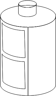
In the next steps, you will make a copy of the left side of the canister and use the transformation handles to make it smaller. Then you will make a copy of this smaller object. Later in this lesson, you will apply a gradient fill to add some dimension to the film canister.
1) Using the Pointer tool, select the left side of the canister with the Pointer tool and then choose Edit > Clone.
The clone of the object is selected.
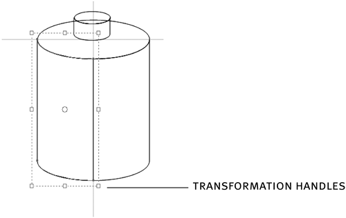
2) Double-click the outline of the cloned object.
The object displays transformation handles.
3) Position the pointer over one of the corner handles and drag toward the middle of the object. Press Tab to release the transformation handles.
As you drag, the object gets smaller. You want the object less than half the height and about 70 percent of the width of the original object. If you drag a corner handle, you change both the width and the height. If you need to change just the height or the width, drag one of the side handles. To scale the width and height proportionally, hold down Shift as you drag a corner handle.
Note
If you want to change the shape of the curve of the interior object, use the Pointer tool to select a point and then use the arrow keys to nudge the point upwards or downwards.
4) Position the new object toward the top of the left side of the canister. Hold down Alt (Windows) or Option (Mac OS) and drag to make a copy of the new shape. Add Shift as you drag to constrain the copy as you drag.
5) Save your file.
Using the Reflect Panel and the Mirror Tool
If you know the exact angle that you want an object reflected, you can use the Reflect panel instead of the Reflect tool. Using the Reflect panel, you can reflect a single object, or you can make copies of the object as you reflect it. By default, the object is reflected around its center point, but you can change the reflection point if you prefer.
The Mirror tool lets you clone and reflect an object a specific number of times in one click. You could have used this tool to clone and reflect the canister body; it is also great for creating geometric patterns and designs.
You’ve already used the Reflect tool on your image, but you will now experiment with the Reflect panel and the Mirror tool to see how they work as well. In the next steps, you will type some text off to the side of your page and use the Reflect panel and then the Mirror tool to create and then reflect a copy.
1) Select the Text tool and type some text on the pasteboard; for example, type your name.
Remember that the pasteboard is anywhere outside the boundaries of the page. Since you are just experimenting with other reflection methods, the pasteboard is a convenient location to place your text.
2) Double-click the Reflect tool on the Tools panel to open the Reflect panel.
The Reflect panel is in the Align and Transform panel group along with the Scale, Rotate, and Skew panels. Here you can enter the reflection axis in degrees, specify the center point of the reflection, and select options to reflect the contents and fills of the object.
The X and Y values indicate the center point of the text block. If you reflect the text and make a copy, the copy is placed on top of the original, reflected on that center point. However, you want the copy reflected and placed to the right of the original text. In the next step, you’ll change the center point of the reflection.
3) Hold down Alt (Windows) or Option (Mac OS) and click the right side of the text block.
The X and Y values for the center point change to the position where you clicked the text block.
Note
You must have the Reflect tool selected when you press the Alt or Option key to change the center point of the selected object. If you don’t see the star cursor, the Reflect tool is not selected.
4) Enter 90 as the reflection axis angle, enter 1 as the number of copies, and click Reflect.
A copy of the text is reflected to the right of the original text block, flipping over the new center point. When you enter 90 degrees as the reflection angle, you reflect the object across its vertical axis. If you’d entered 180 degrees as the reflection angle, the object would be reflected across its horizontal axis. Positive numbers reflect the object counterclockwise; negative numbers reflect the object clockwise.
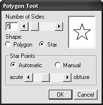
5) Select the Polygon tool; then double-click the tool to open the Polygon Tool dialog box. Select Star as the shape, type 5 as the number of sides, and select Automatic as the Star Points option. Click OK. Drag to draw a star.
You will next use the Mirror tool to reflect the star multiple times.
6) Choose Window > Toolbars > Xtra Tools.
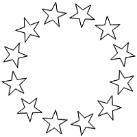
7) Double-click the Mirror tool to open the Mirror dialog box. Select Multiple from the pop-up menu, type 12 as the number of copies, choose Rotate, and click OK.
In the top pop-up menu, you can choose the reflection angle you want to use: Vertical, Horizontal, Horizontal and Vertical, or Multiple.
8) Drag the star. Release the mouse when you see a pattern of stars.
The Mirror tool reflects objects around a center point. As you drag, you see a preview of the objects you are reflecting. In this case, you are creating 12 stars.
You don’t need the text or the star pattern you drew to experiment with these tools. You can delete them, or you can leave them if they are on the pasteboard.
Using the Color Mixer
You can add colors to objects in a variety of ways, and you can easily add, edit, or change the colors you use in your drawings.
You have a choice of three color models for mixing colors: CMYK, RGB, and Spot. The color model you choose depends on how you plan to use your drawing. If you are planning to export your drawing and use it in a print publication that includes color photographs, for example, choose CMYK because you will need to use at least the four process inks (cyan, magenta, yellow, and black) to print the photographs. If you are printing your document with spot colors, choose either CMYK or RGB.
If your drawing is destined for online distribution (for use on a CD or the web), choose RGB or the System color model. If your drawing is headed for the web, you may also want to stick to web-safe colors.
The number of colors computer monitors display depends on the bit depth of the monitor. An 8-bit monitor displays 256 colors; a 24-bit monitor displays 16,777,216 colors (or millions of colors). In the early days of the Internet, color monitors displayed only 256 colors. To make web pages display colors correctly, you need to create your artwork using only 256 colors. In addition to the 256-color restriction, web browsers have a palette of only 216 colors common to both Windows-based and Macintosh computers. These colors are commonly called web-safe colors. Using a web-safe color ensures that your colors are displayed correctly on any computer.
If you don’t use web-safe colors, then the colors in your graphics won’t appear exactly as they were defined for users with only 8-bit color monitors. Colors other than web-safe colors dither on the screen. Dithering is a process of combining two colors to fake a color. For example, to achieve an orange color, the monitor might alternate red and yellow colors instead of displaying one solid color. The problem with dithering is that the resulting color looks grainy.
In the next steps, you will use the Color Mixer to mix a color and then save that color on the Swatches panel.
1) Choose Window > Color Mixer to open the Mixer panel.
The Color Mixer is in the Mixer and Tints panel group. You can also open that panel group to access the panel if it is within the panel docking area.
2) Select RGB as the color model; then type 252 in the R text box, 237 in the G text box, and 0 (zero) in the B text box.
As you enter the values, the color ramp displays the mixed color. You should see a yellow color on the ramp.
3) Click Add to Swatches on the Color Mixer panel. In the Add to Swatches dialog box, choose Spot and then click Add.
After you mix a color, you can save it on the Swatches panel for coloring other objects in your drawing.
Note
Due to a bug in Freehand, the numbers you add to the Swatches panel are often off by one. This is the result of a numeric roundoff problem, but your values should match just fine.
Using the Swatches Panel
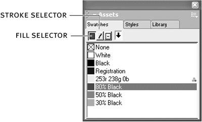
You use the Swatches panel to store your mixed colors, name your colors, apply colors, duplicate colors, import colors from color libraries, and convert colors from spot to process, process to spot, and RGB to CMYK. The panel includes selectors for applying colors to the fill or the stroke, or to both the fill and the stroke, of an object.
1) Choose Window > Swatches to open the Swatches panel if it is not already open.
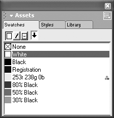
The Swatches panel is in the Assets panel group. You can also access the Swatches panel by opening this panel group if it is closed. The panel should display the yellow color you just created. The name of the color is the name of your color mix: 252r 237g 0b.
Note
If the color is a process color, the name of the color appears in italics. The names of spot colors appear in plain text, as shown for your yellow color.
2) Drag the yellow color chip from the Swatches panel and drop it on the right side of your film canister.
FreeHand provides several methods for applying colors to objects on a page. The film canister is a large target, so in this case you can use the drag-and-drop method. For smaller objects, you can first select the object and then drop the color chip on the fill selector on the Swatches panel. You can also add a fill from the Object panel and then change the color from the color pop-up menu on the panel.
Using the Tints Panel
Tints are lighter versions of a color. Shades of gray, for example, are just percentages or tints of black. Once you create your color, you can use the Tints panel to create the tints. In this task you will create several tints of black and then use them to color portions of your film canister. Then you will use the tints as part of a gradient.
Note
Tints retain a relationship to their parent color. This means if you alter the parent color, the tint changes as well. If you make a tint from a spot color, the tint prints on the same plate as the parent color.
1) Click the Tints tab in the Mixer and Tints panel group.
The Tints panel is initially grouped with the Color Mixer in the Mixer and Tints panel group.
2) Choose Black from the color pop-up menu.
All of the colors that you have added to the Swatches panel, plus black and white, appear in the pop-up menu. After you pick the color, you’ll see nine tints ranging from 10 percent to 90 percent. You’ll also see a color slider and percentage text box where you can enter any number between 0 and 100.
3) Click the 50 percent color chip to select that tint.
You could also drag the slider to 50 or type 50 in the percentage text box.
When you select a tint, the color ramp is divided into two sections. The left side displays the original color; the right side displays the selected color.
4) Position the pointer on the gray color on the ramp and drag it to the Swatches panel.
As you drag, you see a gray color chip. After you release the mouse button, the color is added to the Swatches panel.
Power Tip
Hold down Alt (Windows) or Option (Mac OS) and click a color on the Swatches panel to open the Tints panel with that color.
5) Repeat steps 3 and 4 and add 80 percent and 30 percent black to the Swatches panel.
The colors you add to the Swatches panel are added at the bottom of the list. If you want to change the order in the list, drag the name of the color up or down in the list.
Note
You can also drag the tint color chip on the Tints panel to the Swatches panel.
6) Drag the 50% black tint from the Swatches panel to the top ellipse of the film canister.
As long as the object is large enough for the color chip, you can drop a color on an object even though the object is not selected. If your object is too small, you may need to select it first or change the view magnification to make the object larger.
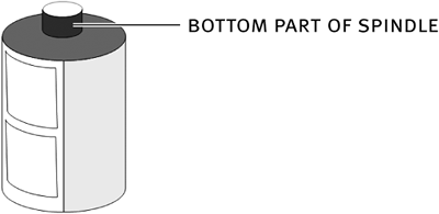
7) Select the bottom part of the spindle on top of the film canister.
Since this part is small, you will use another method to change its fill color.
8) Drag the 80% black color chip from the Swatches panel to the Fill selector at the top of the panel. Drag the black color chip to the Stroke selector.
9) Select the top ellipse of the spindle. Drag the black color chip to the Fill selector and the 30% black color chip to the Stroke selector.
Adding a lighter color to the stroke should make the top part of the spindle more prominent.
10) Change the fill color of the two shapes on the left side of the canister to 30% black and then change the left side of the canister to black.
If you’d first changed the fill of the left side of the canister, you wouldn’t see the outlines of the two shapes on top since their strokes are black. However, you could still drop the gray color on them even without being able to see them.
11) Save your file.
Adding Gradients
Adding colors to your film canister makes it look better, but the colors are flat and don’t show the viewer the three-dimensional quality of the item. To aid in that illusion, you will add a gradient fill, which provides a smooth transition from one color to another. Look at any shiny, round object and you’ll see a variation in color where light hits the surface.
To add some dimension to your film canister, you will add a gradient to the two shapes on the left side of the canister.
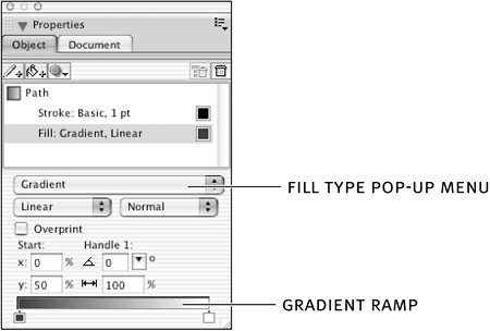
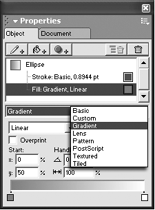
1) Select the top left shape on the canister. Select the Fill property on the Object panel. Choose Gradient from the Fill Type pop-up menu.
When you change the fill type, the Object panel changes to display options for that fill type. The default gradient is Linear. Your selected shape should now contain a linear gradient, from 30% black to white. FreeHand uses the original fill color of the object as the first color and uses white as the second color. Those colors should appear on the gradient ramp on the Object panel.
Tip
You can click the color pop-up boxes on the gradient ramp to change the colors of the gradient.
On the selected object, you will see a start point (a filled circle) and a gradient handle (a filled square) for the gradient. (Radial and Rectangle gradients display two gradient handles.) You can drag the start point and the handle to change the effect of the gradient within the object. Dragging the handle up or down changes the angle of the gradient.
Note
The gradient handles of a selected object appear only when the Gradient fill property is selected on the Object panel.
The Object panel displays the X and Y values for the start point, the angle of the handle, and the length of the handle as percentages of the width of the object. You might want to experiment by moving the handle and the start point to see the effects on the gradient in the object. To return the gradient start point to the edge of the object, drag the start point back, or type 0 in the X text box on the Object panel. To extend the handle to the other side of the object, type 100 as the length percentage.
Power Tip
Double-click either the start or the end point of the gradient handle to quickly return the point to its original position.
You can specify the type of gradient you want and the behavior of the gradient. FreeHand offers six types of gradient: Linear, Radial, Contour, Logarithmic, Rectangle, and Cone. You want the Linear gradient for this exercise, but you may want to experiment with the other types to see the different effects you can achieve. Use the pop-up menu on the Object panel to change the gradient type.
You can also change the gradient behavior by selecting an option from the behavior type pop-up menu. Your choices here are Normal, Repeat, Reflect, and Auto Size. When you choose Normal, the position of the end points determines the length of the gradient. When you choose Repeat, the gradient repeats a specific number of times. When you choose Reflect, the colors in the gradient transition from one end of the color ramp and then back, repeating the number of times specified. When you choose Auto Size, the length of the gradient is set to the exact width and height of the object. The gradient handles do not appear when you choose Auto Size; if you want to adjust the gradient, use the attribute settings on the Object panel.
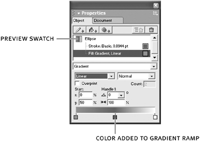
2) Drag the 50% black color chip from the Swatches panel to the middle of the gradient ramp on the Object panel.
You just added a new color to the gradient, and you should see the results in the object. You can move the color chip left or right to change the position of the color in the gradient. Try moving it closer to the left color chip to see if you get the effect of a cylinder.
Note
You can add up to 32 colors on a gradient ramp. To delete a color from the gradient ramp, just drag it away from the ramp.
3) Select the top ellipse of the spindle on the top of the film canister. Select the Fill property on the Object panel and change the fill type to a Radial gradient. Drag the black color chip to the left chip in the gradient, and drag the 50% black color chip to the right chip in the gradient.
You should see a subtle change in the ellipse; it should look like a hollow cylinder. Experiment with other tints of black if you want to change the look even more.
Power Tip
You can drag the preview swatch on the Object panel of a selected object and drop it on other objects. The attributes of the selected object are copied to the target object.
Using the Styles Panel
As you create the fills and effects for your objects, you may need to use the exact fill that was applied to other objects. For example, you just applied a gradient to one of the shapes you added to the film canister. That gradient needs to be applied to the other shape you added as well. You could just delete the second shape and then make a copy of the shape with the gradient. That method would work just fine; that is how you originally created the second shape. FreeHand provides another way as well: you can save the gradient fill in the Styles panel and apply it from there.
Styles are simply named collections of formatting attributes. If you are familiar with style sheets in word processing or page layout programs, you probably already have a good idea of how styles work. Not only can you save text styles for your work in FreeHand, but you can also save graphic styles. You’ll work with text styles in Lesson 7, “Page Layout and Printing.” For now, you will learn only about graphics styles.
Whenever you find yourself choosing the same formatting attributes for objects, you should consider saving those attributes as a style. Not only will this speed up your production time, but it will also ensure consistency throughout your document. In addition, if you change an attribute of a style, all objects using that style will be changed automatically when you redefine the style. For example, suppose your drawing uses a red color that matches the red of a company logo, and the company changes the logo color and you need to update your drawing. Instead of having to change the color of each individual object, you simply need to redefine the style with a different color, and your entire document will be updated instantly.
In FreeHand, the best way to create a style is by example. You’ve already created the gradient. In the next steps, you will save your gradient as a style and then apply it to the other shape.
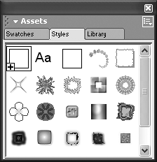
1) Choose Window > Styles to open the Styles panel.
The Styles panel is grouped with the Swatches and Library panels in the Assets panel group. If the panel group is already open, you can also click the Styles tab to open the panel. The panel has three default styles: Normal for graphics, Normal for text, and Normal for connectors. (Connectors are covered in a later lesson.)
2) Choose Large List View from the Options menu on the Styles panel.
The Options menu is located at the top right on all panels. Click the icon (which looks like a series of three dots and lines) to access the menu.
You can view styles in three ways on the panel: using Compact List View, Large List View, and Previews Only. Previews Only (the default) displays only a picture of the style and is not very informative. The two list views display a picture and the style name. If you have many styles defined, you may prefer the compact view so you can see more styles on the panel.
3) Select the shape that contains the gradient. Choose New from the Styles panel Options menu.
A new style with the attributes of the selected object is added to the end of the style list and named Style-1.
Power Tip
You can also create the new style by dragging the object onto the Styles panel or dragging the preview swatch of the object onto the Styles panel.
4) Double-click the default name of the new style, Style-1. Type Gradient as the style name and press Enter (Windows) or Return (Mac OS) to apply the name to the style.
The name of your style is not limited to a single word, as you’ve used here. If your document uses several gradient styles, name each one to describe its attributes.
5) Select the second shape on the left side of the canister and select the new Gradient style from the Styles panel.
The style is applied to the shape. The two shapes are now identical.
Power Tip
You could also drag the style swatch and drop it on the second shape to apply the style to the object.
Tip
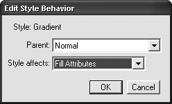
When you applied the style, all of the attributes (the stroke and fill, for example) were applied to the new object. You could change the style so that only the fill is applied to objects. Select the style name on the Styles panel and choose Style Behavior from the Style Options menu. Choose Fill Attributes from the Style Effects pop-up menu in the Edit Style dialog box.
Drawing the Bar Code
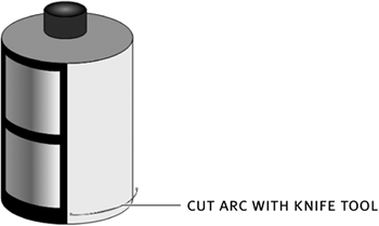
Your film canister is almost complete, but you still need to add some text and the bar code. In Lesson 1, you used the Blend tool to create a specific number of equally spaced lines. To create the bar code, you will use a similar method. First, you need to create one of the lines that will be used for the bar code. The line needs to mimic the curvature of the canister bottom. There are several methods for creating the arc. Here, instead of trying to draw the arc, you will make a copy of the right side of the canister, split the object, and then use the Knife tool to make the arc smaller. You’ve already learned all of the skills needed for this task, making this next exercise a good review. You may want to try drawing the bar code on your own. If so, just skip the following steps.
1) Make a copy of the right side (the yellow side) of the canister and move it off to the side.
Use any method you’ve learned to make the copy.
2) Drag the selection rectangle around the copy to select all of the points.
The four points of the object should be hollow, indicating that the points are selected.
3) Choose Modify > Split. Press Tab to deselect everything. Select and delete the top and side objects.
You need only the bottom portion of the split object.
4) Move the arc over the yellow part of the canister, toward the bottom.
This curved line is the bottom line of the bar code. It is longer than the canister and needs to be cut. In the next step, you will use the Knife tool to make the line smaller.
5) Select the Knife tool and drag it vertically through the selected curved line to make the cut. Press Tab to deselect everything and then select the line to the right of your cut. Delete this portion.
The resulting curved line should follow the curvature of the bottom of the canister. Now you just need to make some copies of the line and blend them to create the bar code.
Power Tip
The Knife tool works only if the object is selected. If the object is not selected when you choose the Knife tool, you can press Ctrl (Windows) or Command (Mac OS) to change to the Pointer tool and then select the line. When you release the Ctrl or Command key, the cursor returns to the Knife tool. This shortcut for the temporary Pointer tool works with any of the other tools and is a real time saver.
6) Use the Alt-drag or Option-drag method you’ve learned to make two copies of the new curved line. Hold down Shift as you drag to constrain the movement.
You don’t want the two new lines equally spaced. Make the space between the first and second lines bigger than the space between the first line and the original line.
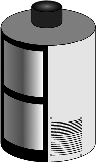
7) Hold down Shift and select the three lines. Choose Modify > Combine > Blend. On the Object panel, change the number of steps for the blend to 8.
You can experiment with the number of steps to see what results you like the best.
8) Save your file.
Using the Subselect Tool
You use the Subselect tool to select items in a group or, in this case, to select the lines that make up the bar code. If you select the bar code with the Pointer tool, you’ll see that the lines are grouped. You could ungroup the objects, but then you’ll need to select them all again to regroup them. By using the Subselect tool, you can select and change an element within a group. When you deselect the item, it remains grouped with the other items.
To make the bar code look more realistic, you will change the point size of each of the three lines of the blend.
1) Select the Subselect tool from the Tools panel.
The cursor changes to the hollow pointer of the Subselect tool.
2) Select the bottom line of the bar code. On the Objects panel, change the size of the stroke to 1.75 points. Select the middle line in the bar code and change its stroke to 1.5 points. Select the top line of the bar code and change its stroke to 0.5 points.
The widths of the lines in the blend now vary from 0.5 to 1.75 points.
Power Tip
You can temporarily access the Subselect tool by holding down Alt (Windows) or Option (Mac OS) when you have the Pointer tool selected. If you have another tool selected, hold down Ctrl+Alt (Windows) or Command+Option (Mac OS) to access the Subselect tool. Using one of these methods is generally faster than choosing the tool from the Tools panel. When you release the modifier keys, you are returned to the originally selected tool.
3) Save your file.
Note
When you use the Subselect tool or the Subselect shortcut on a blend, you can select only the original items used to create the blend; you can’t select the items created by the blend. If you want to make a change to each individual item, you will have to ungroup the blend. Choose Modify > Ungroup twice to access the individual lines. Once you ungroup the blend, it is no longer a blend, which means that you can’t change the number of steps.
Using the Arc Tool
An alternative method for drawing the bar code is to use the Arc tool. The Arc tool draws a quarter of an ellipse. The advantage to drawing the arc as you did previously is that the curvature of the arc exactly matches the curvature of the canister. Using the Arc tool is faster but may not be as accurate.
1) Choose Window > Toolbars > Xtra Tools.
2) Double-click the Arc tool to access the Arc tool options. Select Create Open Arc and Create Flipped Arc. Leave the other option deselected. Click OK.
FreeHand gives you three options for creating an arc:
• Create Open Arc creates a single-line path between the end points of the arc. When this option is not selected, FreeHand joins the paths to create a pie shape.
• Create Flipped Arc flips the orientation of the arc.
• Create Concave Arc creates an arc with an outer corner.
3) Position the pointer just above the bottom of the film canister on the right side. Drag to draw the arc.
As you drag, you control the curvature of the arc. Drag up to make the curvature more pronounced. If you are not happy with the shape of the arc, you can delete the arc and try again. You can also use the Pointer tool to select one of the end points and then use the arrow keys to slowly adjust the arc.
4) Repeat from step 6 in the section “Drawing the Bar Code” to draw the remaining parts of the bar code.
If the arc is too long on one side, you can use the Knife tool to cut off that end. Make the cut before creating the additional copies.
Rotating Items
You are almost done; but don’t take a break yet. The last task to complete the film canister is to add some text. You want the text to appear vertically on the canister. You can rotate items in several ways: you can use the Rotate tool, the Rotate panel, or the transformation handles.
1) Select the Text tool and type the following text: ISO 200 FILM. Format the text as Arial Black, 10 points.
Place the text to the side of the film canister for now. You will move it on top of the canister after you rotate it.
Note
The size of the text depends on the size of your canister. You can change the point size if you need to after you rotate the text.
2) Choose Window > Toolbars > Info.
The Info toolbar displays the X,Y position of the pointer and the center point and angle of rotation as you rotate the text.
Note
In Windows, the information is also displayed in the Status toolbar.
3) Select the Rotate tool on the Tools panel.
Remember that the Rotate tool is grouped with the Scale and Reflect tools. You get the same star cursor as with the Reflect and Scale tools.
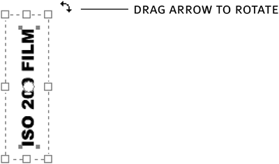
4) Click within the text block and hold down the mouse button. Move the pointer away from the text block and drag up until you see “angle:90” displayed in the Info panel.
The place you clicked becomes the center of rotation. By moving the pointer away from the center point, you can more easily control the angle of rotation. The closer the pointer is to the center point, the faster the object rotates around the center point. If you add Shift as you rotate the object, the rotation is constrained to 45-degree angles.
5) Use the Pointer tool to move the text block above the bar code.
After you place the text block, you may need to change the point size. You can still change the size even though the text block is rotated. Use the Object panel as you normally would to change the size.
6) Save your file.
Although the Rotate tool is easy to use, there are times when you may prefer to use the other methods of rotating objects. For example, if you know the angle you want to use, you can enter the angle on the Rotate panel instead of dragging the object around a center point. To access the panel, double-click the tool as you did to access the Reflect panel. Type the rotation angle and then click Rotate. Notice that you can choose to rotate only the object and not the contents and fills. (Deselect both Contents and Fills on the panel to rotate only the outline of the object.) This option is available only when you use the Rotate panel.
You can also double-click the object with the Pointer tool to display the transformation handles. Move the pointer to one of the corner handles until you see the curved double arrow. Hold down Shift as you drag around the object to constrain the rotation. Press Tab to release the transformation handles.
What You Have Learned
In this lesson, you have:
• Split and joined paths (pages 68–72)
• Reflected and scaled objects (pages 72–77)
• Used the Reflect panel and the Mirror tool to flip objects about an axis (pages 77–80)
• Used the Color Mixer and Tints panel to create colors and added those colors to the Swatches panel (pages 80–86)
• Created gradients and added them to objects (pages 87–90)
• Used the Styles panel to save attributes of a graphic (pages 90–93)
• Used the Subselect tool to select items in a group (pages 96–97)
• Used the Arc tool to draw an arc (pages 98–99)
• Used the Rotate tool to rotate text (pages 99–101)
