Chapter 3. Smart Light Switch
One of the problems with the current generation of smart lightbulbs is that the smarts are in the bulb.
Though they have been held up as a massive Internet of Things success story, in the long term, this will not turn out to be the case because lightbulbs are something you turn on and off from a switch on the wall. You can make most smart lightbulb systems unresponsive by using the wall switch. Effectively, a smart lightbulb replaces a thing we use every day, the light switch, but it does it poorly. We really need to replace the switch, not the bulb.
What Is a Smart Switch?
A smart light switch not only lets you turn the light on and off using the switch itself but also remotely via Bluetooth LE. The switch should also know its current status—in other words, whether the bulb is on or off—and send a notification over Bluetooth to subscribed applications when the switch is toggled to allow them to update their local status.
Hardware
We need the following hardware to build the light switch:
-
A breadboard
-
An LED
-
A 220Ω and a 10kΩ resistor
-
Jumper wires
-
A tactile button switch
Optionally (see “Using Real Lightbulbs”) we’ll also use a:
The Breadboard
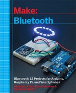
A solderless breadboard (shown in Figure 3-1) is an indispensable tool for rapidly and cheaply prototyping projects.
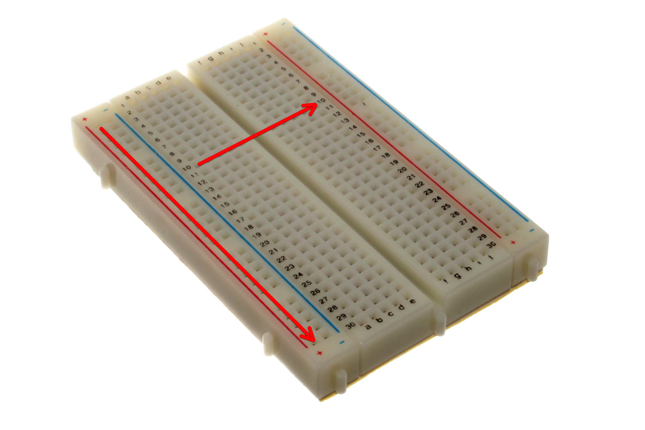
Figure 3-1. A typical half-size breadboard
Breadboards consist of many tiny “holes” arranged on a 0.1-inch grid into which the leads of the component can be connected. Typically, as depicted by red arrows in Figure 3-1, the holes down each side of the breadboard are electrically connected lengthways down the board and are used for the positive and negative (i.e., ground or Earth) power supply. These are usually referred to as rails, and will commonly be labeled as such. The other holes in the board are connected horizontally across the board, usually with a gap down the middle. Each hole is connected to the many metal strips that run underneath the board.
Putting the legs of a component in the same row, therefore, forms connections between different components of your circuit. Typically, you’ll make use of short lengths of wire, commonly referred to as jumper wires, to connect rows of the board.
Note
When using a breadboard, you must use single-core 0.6mm-diameter wire. Stranded wire is not suitable because it will crumple when pushed into a hole, and it may damage the board if individual strands break off.
When using chips with many legs (integrated circuits or, more commonly, ICs), place them in the middle of the board so that half of the legs are on one side of the middle gap that runs down the board and half are on the other side. Since the chip spans the gap in the middle of the board, the legs on one side of the chip will not be electrically connected to the legs on the other side of the chip.
Getting Started
Blinking an LED is the Hello, World of hardware. We are going to blink an LED to ensure your hardware and programming environment are set up correctly.
Resistor Color-Coding
Before you try to wire anything up, you need to get familiar with how resistors are labeled so you can be sure to choose the right ones.
A color code (see Figure 3-2) is normally used to denote the resistance value of a resistor. Normally, there will be four bands: three on one side to tell you what the resistance of the component is, and then a gap, and another band off to the side to tell you the tolerance of the component. In some cases, there may be an additional band as part of the resistor value, but it’s fairly rare.
Orient the resistor so that the band that is separated from the others is on the right, and then read the color bands left to right. In the case of our 10kΩ, we see that the bands are brown, black, and orange, which translates to 1, 0 (so 10), and then a multiplier of 1kΩ (hence 10kΩ).
To the right of this is a gold band, which means that our resistor is 10kΩ ± 5%.

Figure 3-2. Resistor color-coding chart
Blinking an LED
Let’s go ahead and start building. Grab your Arduino board, a breadboard, an LED, a 220Ω resistor, and some jumper wires.
Note
It’s standard practice to use red wires for power (VCC), which in our case is +5V, and black wires for ground (GND). This helps a lot later on when you’re struggling with a breadboard full of components and trying to figure out where all the wires are going.
Connect the +5V pin on your Arduino to the positive rail of the breadboard, and one of the ground (GND) pins to the negative rail. Next, grab the LED and the 220Ω resistor from your pile of parts.
An LED is a light-emitting diode, and diodes only allow current to flow in one direction, so we need to make sure we plug things in correctly. We need the resistor to limit the amount of current that flows through the LED; otherwise, it’s liable to burn out.
Most LEDs have a long and a short lead. The longer lead is the positive lead, or anode. The negative lead or cathode is the shorter lead. Depending on the LED, one side of the LED may be flatter; this is the positive (anode) side.
Take the 220Ω resistor and the LED and wire them up as shown in Figure 3-3, remembering to connect the short leg of the LED toward GND.
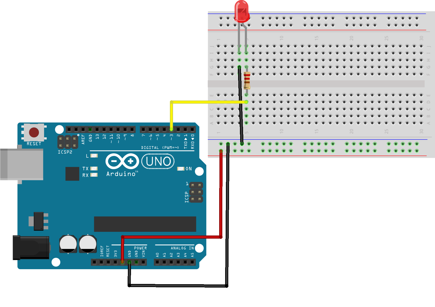
Figure 3-3. Wiring an LED to our Arduino board
Now that you’ve wired your circuit together, go ahead and open the Arduino IDE. There are a number of example sketches included in the development environment, and one of them will do just what we want. The one we’re looking for can be found by selecting File → Examples → 1.Basics → Blink, which is shown in Figure 3-4.
Figure 3-4. The Blink example sketch
Every Arduino sketch consists of two parts: the setup and the loop. Every time the board is powered up, or the board’s reset button is pushed, the setup( ) routine is run. After that finishes, the board runs the loop( ) routine. When that completes, and perhaps somewhat predictably, the loop( ) is run again and again. Effectively, the contents of the loop( ) sit inside an infinite while loop.
Before building and deploying this example to our Arduino, let’s take a look at the code:
voidsetup(){pinMode(13,OUTPUT);}voidloop(){digitalWrite(13,HIGH);delay(1000);digitalWrite(13,LOW);delay(1000);}

We set pin 13 to behave as an OUTPUT pin. In this state, the pin can provide up to 40 mA of current to other devices. This is enough current to brightly light up an LED, or run many sensors, but not enough current to run most relays, solenoids, or motors.

If the pin has been configured for OUTPUT, its voltage will be set to the corresponding value: 5V for HIGH, 0V (ground) for LOW.
Effectively, then, this piece of code causes the voltage on pin 13 to be brought to HIGH for a second (1,000 ms) and then LOW for a further second before the loop starts again, bringing the voltage to HIGH once more.
Note
As mentioned in Chapter 2, some of the digital pins on the Arduino board have special functions; pin 13 is one of these. On most boards (including the Uno), it has an LED and resistor attached to it that’s soldered onto the board itself.
We’ve attached our LED on the breadboard to pin 3, rather than 13. So go ahead and edit the code, changing all three occurrences of pin number 13 to pin 3.
Make sure you’re connected to the Arduino, see “Connecting to the Board”, and then go ahead and compile and upload the sketch to your board.
The first step to getting the sketch ready for transfer over to the Arduino is to click on the Verify/Compile button (see Figure 3-5). This will compile your code, checking it for errors, and then translate you program into something that is compatible with the Arduino architecture. After a few seconds, you should see the message Done compiling. in the Status Bar and something along the lines of Binary sketch size: 1,030 bytes of program storage space. Maximum is 32,256 bytes in the Notification area.

Figure 3-5. The Arduino development environment
Once you see that message, go ahead and click on the Upload button (see Figure 3-5 again). This will initiate the transfer of the compiled code to the board via the USB connection.
Wait a few seconds—you should see the RX and TX LEDs on the board flashing as the data is transferred over the serial connection from your computer to the board. If the upload is successful, the message Done uploading. will appear in the status bar.
A few seconds after the upload finishes, you should see the LED start to blink. One second on, one second off. If you see that, congratulations, you’ve just successfully gotten the hardware equivalent of “Hello, World” to compile and run on the Arduino board.
Adding a Switch
Now that we’ve seen how a basic Arduino sketch works, let’s move on and add a switch. We’ll start out with a simple push button, which is called a momentary contact switch. These types of switches come in two types—normally open and normally closed, although normally open are by far the most commonly available. Normally open switches complete a circuit (turn things on) when you press them, and then off when you release them.
The most common type of tactile switch intended for breadboarding has four legs, not two as you might expect. The two legs on each side of the switch are connected together. There are really only two wires here, not four. The two switches in Figure 3-6 are therefore the same.

Figure 3-6. Tactile push-button switches
Grab the push button and a 10kΩ resistor from your parts pile and wire them up on the breadboard as shown in Figure 3-7.

Figure 3-7. Adding a switch
What we’ve done here with the resistor, as you can see in Figure 3-8, is called debouncing the button. If we simply connected one side of the button to +5V and the other to pin 4 of the Arduino without a route to GND via the 10kΩ resistor, the pin would indeed be pulled to +5V when we pushed the button. However, when the button was not pushed—and the two sides of the switch were unconnected—then the pin would be floating because it’s not connected to anything.
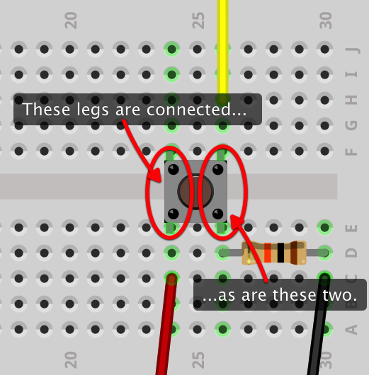
Figure 3-8. How the switch legs are connected
What that means for us is that our code will work unreliably; sometimes we’ll detect button pushes that don’t exist. To avoid that, we use the resistor to pull down the pin connection to GND. So when the the switch is not being pushed, the pin is no longer floating; instead it is pulled to a LOW state.
If you’ve followed the instructions and wired the breadboard as laid out in Figure 3-7, you should have something that looks a lot like Figure 3-9.
Now we’re ready to write the software that goes with the hardware. Open a new sketch by clicking on File→New to open a new window.
#define LED_PIN 3#define BUTTON_PIN 4intval;voidsetup(){pinMode(LED_PIN,OUTPUT);pinMode(BUTTON_PIN,INPUT);}voidloop(){val=digitalRead(BUTTON_PIN);if(val==HIGH){digitalWrite(LED_PIN,HIGH);}if(val==LOW){digitalWrite(LED_PIN,LOW);}}
The mode of the pin the LED is connected to is set to OUTPUT, which means we can pull the pin to HIGH or LOW.
The mode of the pin the button is connected to is set to INPUT, which means we can detect whether the pin is being pulled HIGH or LOW.

In the loop we simply check to see if pin 4, the pin the button is connected to, is pulled HIGH or LOW and set the value of the LED accordingly.

Figure 3-9. The Arduino and breadboarded LED and button
Save the contents of the sketch to a file using the File→Save menu item, and then click on the Verify button to compile your sketch—and, if all goes well, the Upload button to upload it to the board. You should see the RX and TX LEDs light up as the code is transferred. When you see the Done uploading. message, go ahead and push the button. While pushing the button, the LED should go on, and when you release the button, it should go off.
Software Debouncing
In addition to hardware debouncing the button, we can do something called software debouncing to add a little bit more reliability to our code. Open up the Arduino browser and modify your code as shown here:
#define LED_PIN 3#define BUTTON_PIN 4intcurrentState;intdebounceState;voidsetup(){pinMode(LED_PIN,OUTPUT);pinMode(BUTTON_PIN,INPUT);}voidloop(){currentState=digitalRead(BUTTON_PIN);delay(10);debounceState=digitalRead(BUTTON_PIN);if(currentState==debounceState){if(currentState==HIGH){digitalWrite(LED_PIN,HIGH);}if(currentState==LOW){digitalWrite(LED_PIN,LOW);}}}
Read the switch state once and then, 10ms later, we read it again.
If we read the same value twice, only then do we change the LED state.
Here, we read the switch state twice, at a very short interval. If both readings are the same, only then do we go ahead and change the state of the LED. While not strictly necessary, since we’ve hardware-debounced the button, it’s common to do both of these steps for reliability.
If you save your code and hit the Upload button to upload the sketch to the board, and then push and release the button, everything should work as before—but ever so slightly more reliably.
Making a Real Light Switch
Right now our light switch doesn’t really behave like a light switch. Our wall switches at home are toggles: flip them one way and the light goes on and stays on; flip them the other way and the lights go off and stay off. They wouldn’t be much use if we had to stand and hold the switch down to use them.
We can replicate this by using something called a Single Pole Double Throw (SPDT) switch, as shown in Figure 3-10.
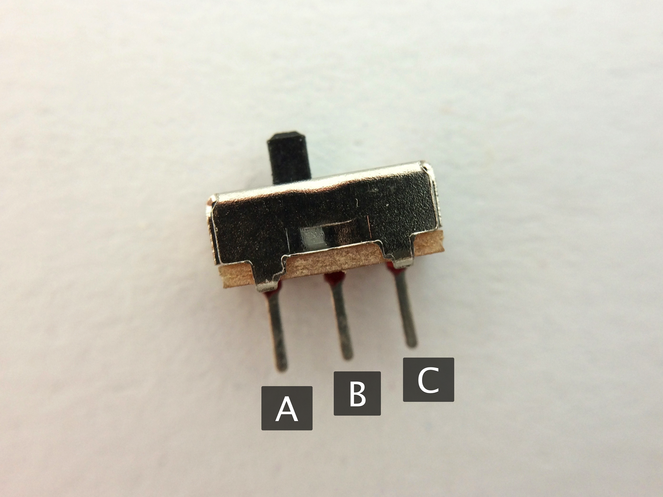
Figure 3-10. A Single Pole Double Throw (SPDT) switch
By Changing the Hardware
An SPDT switch has three terminals (A, B, and C). Generally the middle terminal is the “common” terminal and is usually connected to the supply voltage. When the switch is flipped to one side, two of the three terminals come into contact (A and B), and when flipped to the other side, two other terminals come into contact (B and C).
In our case, wiring B up 5V, and A up to the button pin on our Arduino, remembering to pull down terminal A using our 10kΩ resistor and just leaving C floating, would allow us to replicate a normal light switch without making any changes to our code (see Figure 3-11).

Figure 3-11. Wiring up the SPDT switch to the Arduino
If you’ve followed the instructions and wired the breadboard as laid out in Figure 3-11 the LED should turn on when the SPDT switch is slid to the left, and off when it is slid to the right. No code changes are necessary.
Unfortunately, SPDT switches, especially breadboardable ones, are a lot more expensive than the simple tactile switches we’ve been working with so far. If you don’t have one on hand, or don’t want to spend the extra money, then we can also replicate this in code.
Changing the Software
Going back to our push-button switch then, as we had in Figure 3-7, let’s open the Arduino development environment and modify our code as follows:
#define LED_PIN 3#define BUTTON_PIN 4intcurrentState;intdebounceState;intswitchState=0;intledState=0;voidsetup(){pinMode(LED_PIN,OUTPUT);pinMode(BUTTON_PIN,INPUT);}voidloop(){currentState=digitalRead(BUTTON_PIN);delay(10);debounceState=digitalRead(BUTTON_PIN);if(currentState==debounceState){if(currentState!=switchState){if(currentState==LOW){// Button just released}else{if(ledState==0){digitalWrite(LED_PIN,HIGH);ledState=1;}else{digitalWrite(LED_PIN,LOW);ledState=0;}}switchState=currentState;}}}
We introduce two state variables:
switchStateandledState. When the code is first run, we assume the LED is turned off and the switch is in a “not pressed” state.We only want to change the LED state when the switch state has changed.
However, if the newly measured state of the LED is LOW, then it must previously have been HIGH. The switch has been pressed, and is now being (or has just been) released. We don’t want to do anything at this point.

The only point where we want to toggle the LED state is when the switch state has been changed to HIGH; in other words, the button has just been pressed.
If you save your code and hit the Upload button to upload the sketch to the board, and then push and release the button, the LED should turn on when the button is pushed down and then remain on when you release it. Pushing the button again will turn on the LED, and it should remain off when you release the button.
Adding Bluetooth
Now that we have a working push-button light switch, let’s add some Bluetooth LE. We want to be able to turn the light, or LED in this case, on and off using the physical switch but also via Bluetooth LE.
We’re going to create a Bluetooth LE peripheral with a single service having two characteristics: a readable/writeable characteristic called “Switch,” which is the characteristic we’ll use to flip the switch on and off, and a second characteristic called “Status,” which we can subscribe to be told about changes in the status of the switch.
We also need descriptors, which are optional, but we can use the Characteristic User Description 0x2901 to provide a text description of the characteristic value. This is a standard UUID, and tools that know about it can use it to give a plain-text description of our service to an end user.
Our service will therefore look something like Table 3-1.
| Characteristic | UUID | Properties | Comment |
|---|---|---|---|
Switch |
FF11 |
read, write |
1 on, 0 off |
State |
FF12 |
notify |
1 on, 0 off |
But before we go back to our code to implement our service using the BLEPeripheral library we installed in “Installing the BLE Peripheral Library”, let’s go ahead and wire our Bluetooth LE module to our Arduino.
Wiring Up the Adafruit Bluefruit LE Module
The Bluetooth board we’ll be using throughout this book is the Adafruit Bluefruit LE board based around the Nordic Semiconductor nRF8001 chipset.
Warning
You should be careful when purchasing a board, and make sure you’re buying the correct one as Adafruit uses the “Bluefruit” name with all of their Bluetooth LE boards as well as some Bluetooth-LE-like products. For instance, their UART Friend and SPI Friend boards are based around an entirely different chipset but still branded with the “Bluefruit” name.
Wire the board to the Arduino as shown in Figure 3-12, using pin 2 for RDY and pins 9 and 10 for RST and REQ, respectively.
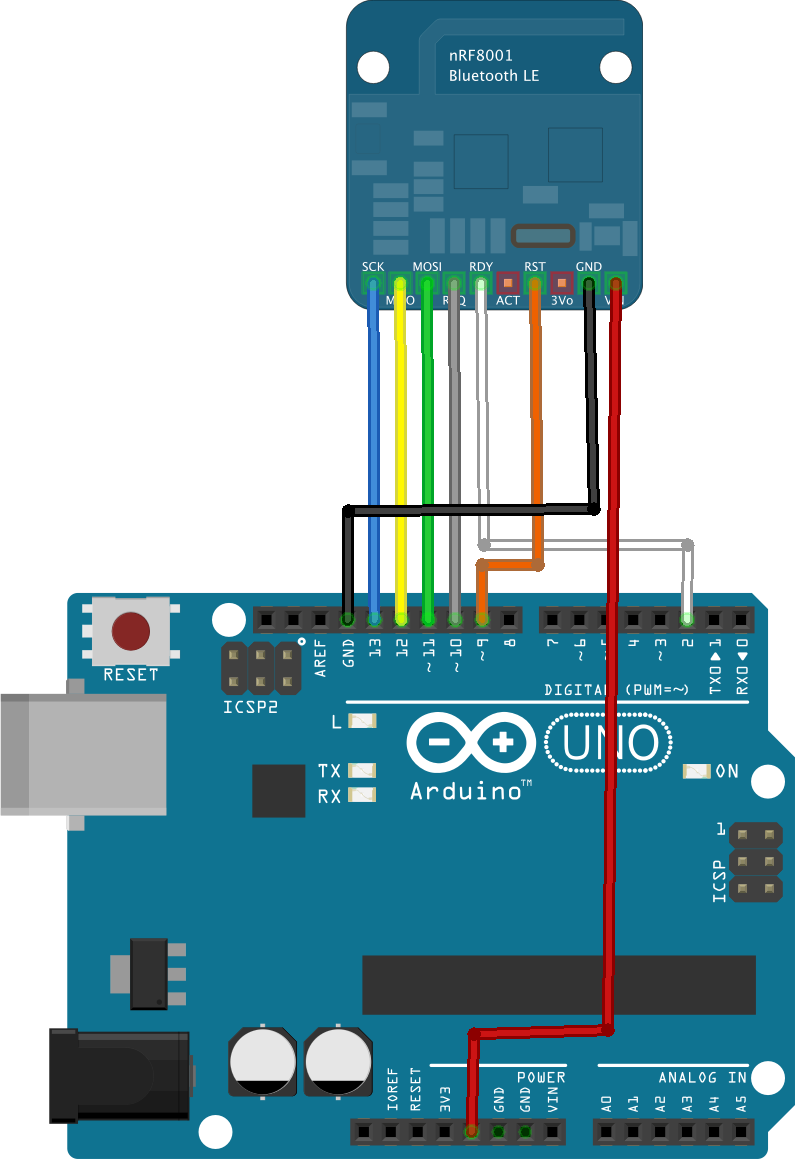
Figure 3-12. Wiring the Adafruit Bluefruit module to the Arduino
With the Bluetooth LE module now wired into the Arduino, you should have something that looks like Figure 3-13.

Figure 3-13. The smart light switch wiring
Modifying Our Sketch
If you’ve followed the instructions and wired the breadboard as laid out in Figure 3-13, you should have something that looks a lot like Figure 3-14.
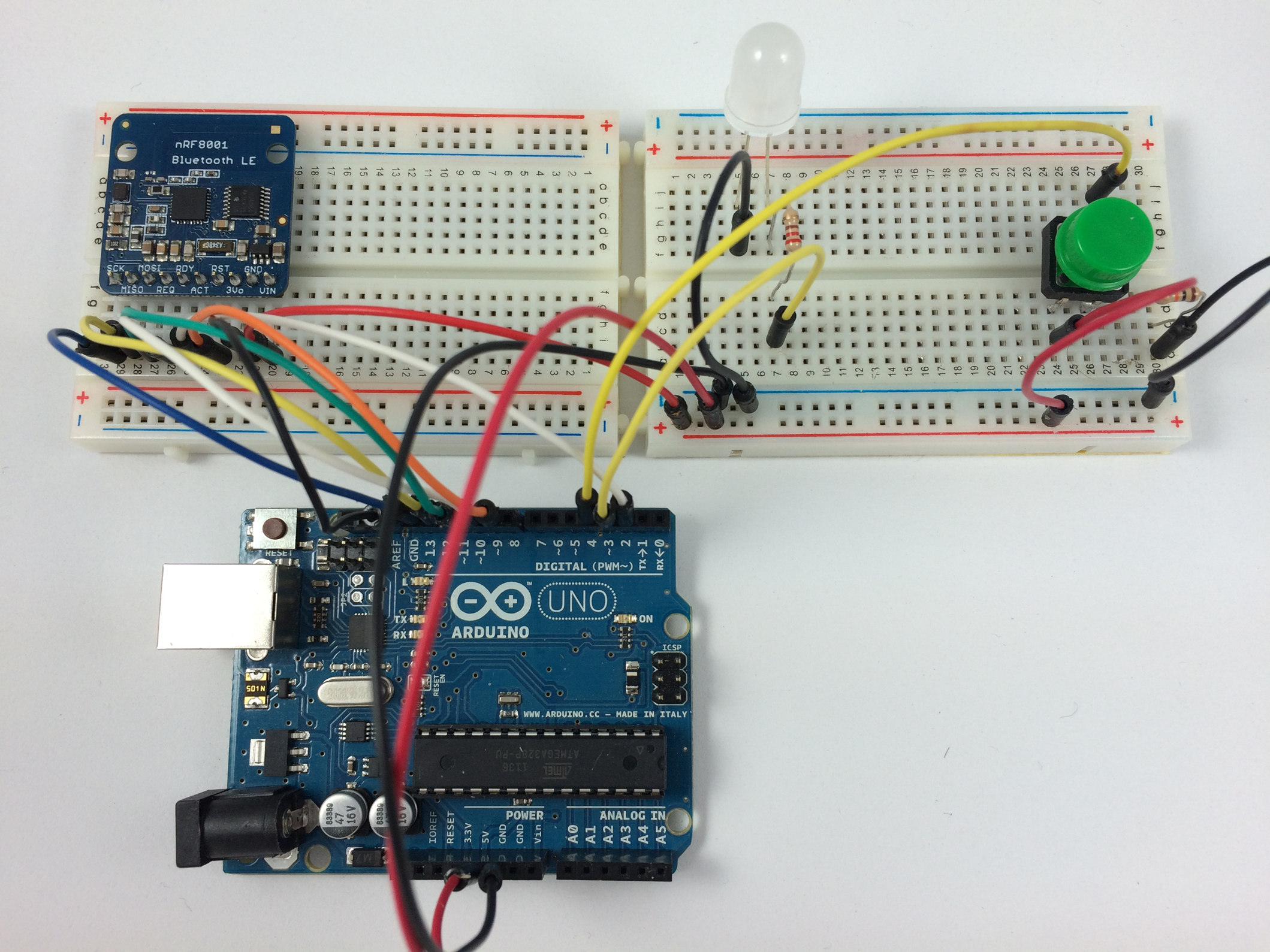
Figure 3-14. The Arduino with Adafruit Bluefruit
Now that we have our hardware wired together, let’s go back to the development environment and modify the code (shown in Example 3-1) for a push-button light switch.
Example 3-1. The push-button light switch code
#include <SPI.h>#include <BLEPeripheral.h>#define LED_PIN 3#define BUTTON_PIN 4#define BLE_REQ 10#define BLE_RDY 2#define BLE_RST 9intcurrentState;intdebounceState;intswitchState=0;intledState=0;BLEPeripheralblePeripheral=BLEPeripheral(BLE_REQ,BLE_RDY,BLE_RST);BLEServicelightswitch=BLEService("FF10");BLECharCharacteristicswitchCharacteristic=BLECharCharacteristic("FF11",BLERead|BLEWrite);BLEDescriptorswitchDescriptor=BLEDescriptor("2901","Switch");BLECharCharacteristicstateCharacteristic=BLECharCharacteristic("FF12",BLENotify);BLEDescriptorstateDescriptor=BLEDescriptor("2901","State");voidsetup(){Serial.begin(9600);pinMode(LED_PIN,OUTPUT);pinMode(BUTTON_PIN,INPUT);blePeripheral.setLocalName("Light Switch");blePeripheral.setDeviceName("Smart Light Switch");blePeripheral.setAdvertisedServiceUuid(lightswitch.uuid());blePeripheral.addAttribute(lightswitch);blePeripheral.addAttribute(switchCharacteristic);blePeripheral.addAttribute(switchDescriptor);blePeripheral.addAttribute(stateCharacteristic);blePeripheral.addAttribute(stateDescriptor);blePeripheral.begin();Serial.println(F("Smart Light Switch"));}voidloop(){blePeripheral.poll();currentState=digitalRead(BUTTON_PIN);delay(10);debounceState=digitalRead(BUTTON_PIN);if(currentState==debounceState){if(currentState!=switchState){if(currentState==LOW){// Button just released}else{Serial.(F("Button event:"));if(ledState==0){stateCharacteristic.setValue(1);switchCharacteristic.setValue(1);digitalWrite(LED_PIN,HIGH);ledState=1;Serial.println(F("light on"));}else{stateCharacteristic.setValue(0);switchCharacteristic.setValue(0);digitalWrite(LED_PIN,LOW);ledState=0;Serial.println(F("light off"));}}switchState=currentState;}}}
Here, we create a peripheral instance using the BLEPeripheral library.
Create a service with UUID of 0×FF10.
Create the Switch Read/Write characteristic and descriptor.
Create the State characteristic and descriptor for notifications.

Set the advertised Local Name and Device Name; see “Device Name Versus Local Name” for more details about why we need to set both of these advertised characteristics.

Set the UUID of the advertised service.

Go ahead and add the service and associated characteristics and descriptors to the peripherals instance.

Begin advertising the Bluetooth LE service.

Poll of Bluetooth LE messages.

Set both the switch and state to be on.

Set both the switch and state to be off.
If you save your code and hit the Upload button to upload the sketch to the board, you should be able to turn the LED on and off as normal using the button, and if you click on the Serial Console button (see Figure 2-2) in the development environment to open the serial console, you should see the string Smart Light Switch appear, with further messages every time you push the button to turn the LED on or off.
However, right now we can read, but we can’t write (change) the state of the LED. In other words, right now we can’t “throw” the switch using Bluetooth LE. We need a handler foundation. Just above the blePeripheral.begin( ), add the following:
switchCharacteristic.setEventHandler(BLEWritten,switchCharacteristicWritten);
Assign an event handler method to be called when a write command is made on the peripheral.
Then, at the bottom of your sketch, after the loop( ) function, add the handler function itself.
voidswitchCharacteristicWritten(BLECentral¢ral,BLECharacteristic&characteristic){Serial.(F("Characteristic event: "));if(switchCharacteristic.value()){Serial.println(F("light on"));digitalWrite(LED_PIN,HIGH);ledState=1;stateCharacteristic.setValue(1);}else{Serial.println(F("light off"));digitalWrite(LED_PIN,LOW);ledState=0;stateCharacteristic.setValue(0);}}
If you save your code and hit the Upload button to upload the sketch to the board, everything should continue to work as before. However, now you have everything in place to control the LED, not just with the button, but via Bluetooth LE. What we need is a generic Bluetooth LE explorer application so we can easily examine and trigger our service.
Testing the Service
If you’re an iOS user, go ahead and install LightBlue on your iPhone or iPad. Alternatively if you’re an Android user, install nRF Master Control Panel on your phone or tablet. The two apps present the same information but do so somewhat differently.
Opening either app will start it scanning for Bluetooth LE devices. You’ll be able to choose a peripheral from a list of nearby devices and explore information about that connected peripheral, its services, and characteristics.
Taking a look at our Smart Light Switch in LightBlue you should see something along the lines of Figure 3-15.

Figure 3-15. Exploring the Smart Light Switch in the LightBlue app
Tapping through from the Smart Light Switch in the peripherals list, you can see the advertisement data for the service showing our two chracteristics: Switch, which is Read/Write, and State, which is Notify. We can register the LightBlue app for notifications when the LED state changes by tapping on the Listen for Notifications button in the State characteristic screen.
Going back, we can then go to the Switch characteristic screen, which shows the current value of the chractersitic, which should be 0x00, meaning the LED is off. Tap on “Write new value” to open the editor. Enter 01 and hit Done; the LED should turn on and the characteristic screen should show the new value as 0x01. If you registered for notifications, you should see a canvas drop-down (see Figure 3-16) to tell you the value has changed.
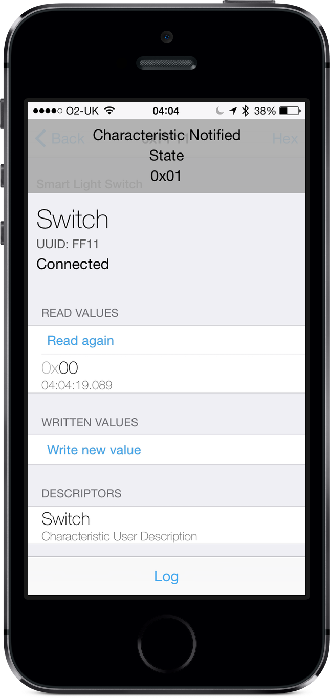
Figure 3-16. We are notified that the state of the LED has changed
If you have the Serial Console open you should also see a Characteristic event: light on message printed in the console. Finally, if you push the button, you should see a further notification in LightBlue that the LED state has changed back to 0x00.
If everything works, that’s it, we have a working smart light switch.
Using Real Lightbulbs
Right now, our light switch is just a proof of concept; turning an LED on and off isn’t actually as interesting as it looks at first. But it’s actually pretty easy to turn our simple breadboarded project into one that can turn a real light on and off.
Here’s what you’ll need:
The PowerSwitch Tail (see Figure 3-17) simplifies our lives by hiding all that nasty AC electricity and letting us use a relay and our Arduino board to turn real mains-powered devices on and off.
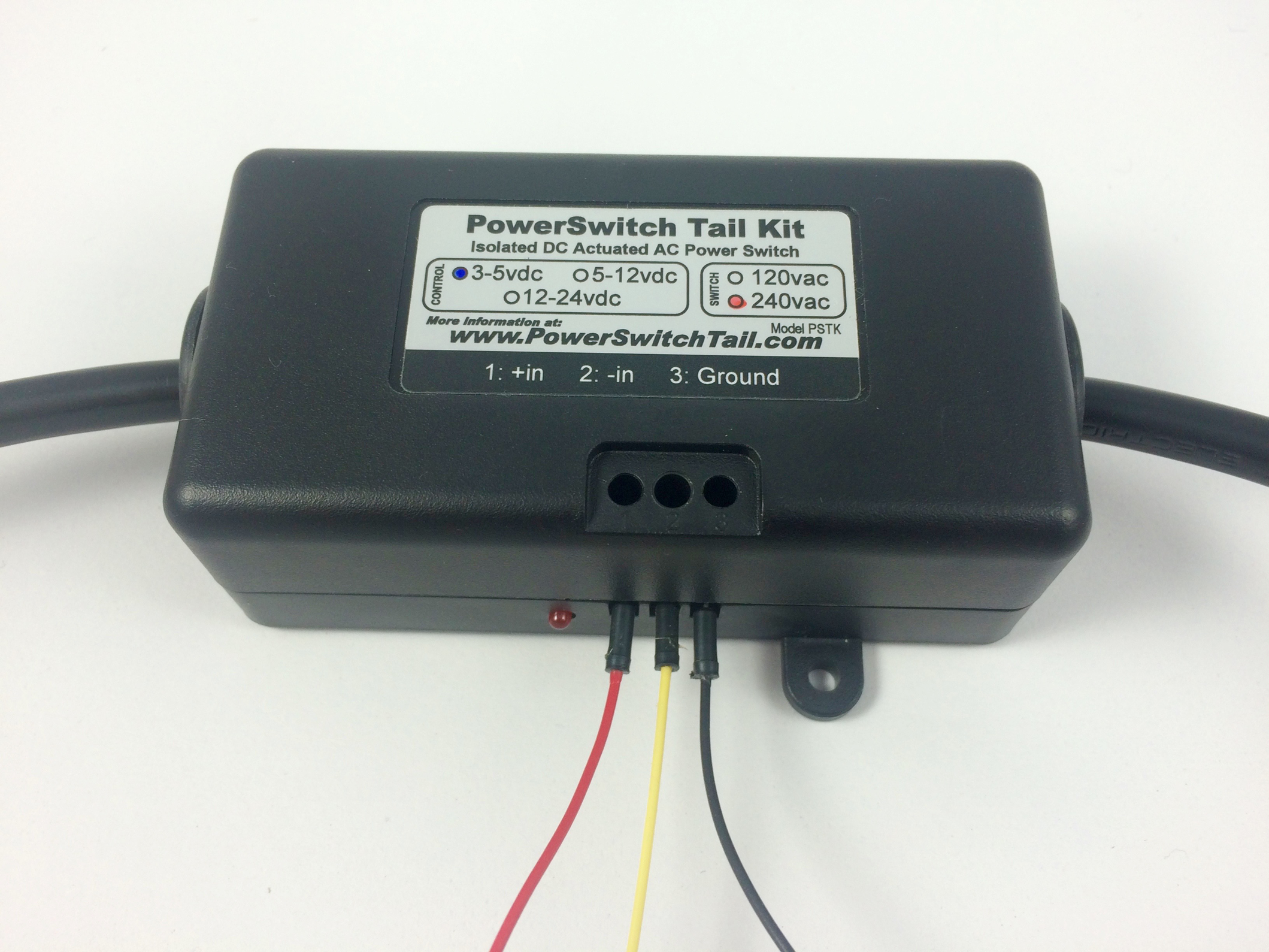
Figure 3-17. The PowerSwitch Tail
On the side of the PowerSwitch Tail, you will need to connect three wires to the terminal block. Use a small watchmaker’s screwdriver to access the screws from the top of the Tail. Turn the screws counterclockwise to open the terminal contacts, and insert the wires into the terminal block contacts through the holes on the side of the Tail.
The left-most contact (labeled +in) is for +5V; the middle wire (labeled -in) is the signal wire; and the right-most wire (labeled Ground) is, as you’d expect, GND.
We then need to make some changes to our hardware. Go ahead and wire up the Arduino, switch, and Powerswitch Tail as shown in Figure 3-18.
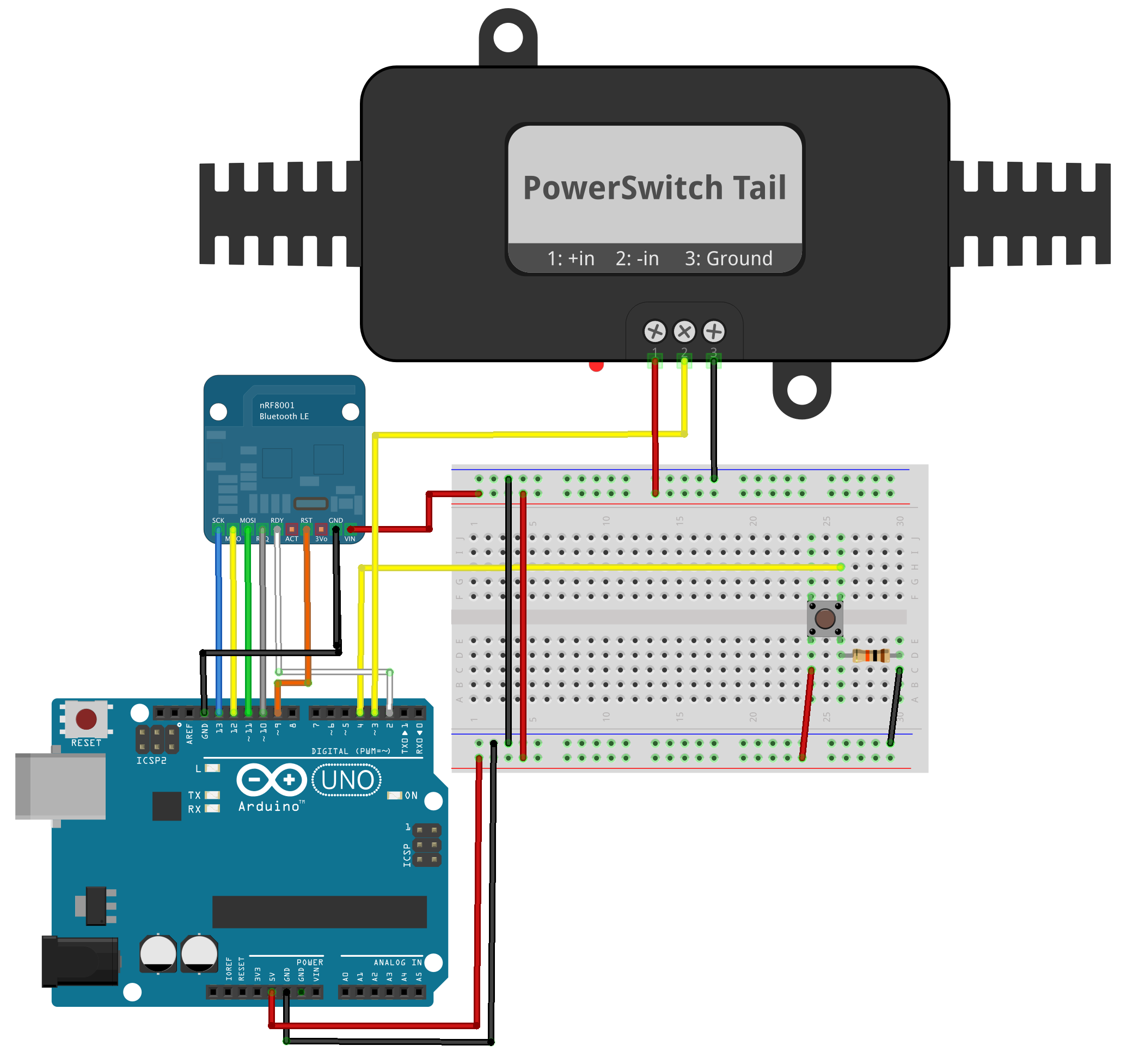
Figure 3-18. Swapping the LED for a PowerSwitch Tail
Then plug the PowerSwitch Tail into the wall, and then plug in a mains-powered lamp or any electrical device (maximum draw is 15amps at 120V) that you would like to control to the PowerSwitch Tail socket.
If you’ve followed the instructions and wired the breadboard as laid out in Figure 3-18, you should have something that looks a lot like Figure 3-19 at this point.

Figure 3-19. The Arduino and the PowerSwitch Tail
The Powerswitch Tail can be wired either as “normally open” or “normally closed.” In the normally open configuration, when the signal (middle) terminal is pulled and held LOW, then the relay is tripped and power will flow from the mains to the attached lamp. Power will only flow while the signal wire is pulled LOW. Conversely, in the normally closed configuration when the signal terminal is pulled and held LOW, then the relay is tripped and power will cease to flow from the mains to the attached lamp.
Tip
Effectively, the default state of the attached mains-powered lamp is off if the Powerswitch Tail is normally open, and on for if it is normally closed. The most common way to wire the Powerswitch Tail is “normally open,” which makes sense from a safety perspective. If there isn’t a signal from the Arduino, then the attached mains device is “off.”
Since pulling the signal wire LOW rather than HIGH is what triggers the relay, in the “normally open” case we have to flip the logic in our code. Go back into the code and everywhere there is a
digitalWrite(LED_PIN,HIGH);
change it to
digitalWrite(LED_PIN,LOW);
and vice versa. In other words, we need to swap the logic around for the LED_PIN, changing HIGH to LOW and LOW to HIGH for the “normally open” case.
Conversely, in the “normally closed” case, the attached lamp will be on when the LED_PIN is pulled HIGH, and then will turn off when we pull the pin LOW, so no change to our code is needed from when we were working with the LED.
Tip
If you swap the LED out for the Powerswitch Tail and the lamp behaves in the opposite manner of what you’re expecting—it turns on when you think it should turn off, and off when you think it should turn on—then just flip the values for the LED_PIN in the code.
If you save your code and hit the Upload button to upload the sketch to the board, everything should continue to work as before. Except now, instead of controlling an LED, you’re controlling a real lamp.