

Photography by Greg MacLaurin
THE DISEMBODIED VOICE OF JUDY GARLAND SPEAKS!

How to make a Ghost Phone.
Currently, I’m obsessed with analog telephones. I don’t know why. My last obsession was with the severed hands of mummies, but let’s not get into that. Today it’s phones. And these Ghost Phones are fun. The idea is simple: hide an MP3 player and its headphone inside an old analog telephone, and you can listen to someone talking to you!
But before we start unscrewing things willy-nilly, let’s take a moment to find out about analog phones and how they work. (I hate reinventing the wheel. I’m all into research.) Privateline.com has a good history of telephone technology, and HowStuff-Works has a technical overview at howstuffworks. com/telephone.htm. Remember, these are just starting points. Please do your own research; you’ll learn something amazing in the process.
Now that you’ve become a font of information on analog telephones, you’re ready to modify one. Here are my instructions for making a Judy Garland Ghost Phone.
1. Record audio and load the MP3 player.
1a. Decide which ghost you want to summon. Think of who the ghost is, and who they’re talking to. Set a scene. All my Ghost Phones are first-person: the ghost totally monopolizes the conversation, and never lets you get a word in edgewise. Even though the ghost might ask a question, they either answer it for you or they just continue talking.
Rotary telephone
Speaker from an MP3 player headphone with cord
MP3 player playing a 30-minute, custom-edited monologue
Female insulated spade lugs (2) for earpiece
Male spade lugs (2) for headphone jack
Electrical tape to insulate connectors
Tape to cover the hole in the bottom of the phone
Audio files Counterpoint-music.com sells a 2-CD set of Judy’s self-recorded notes for her unwritten autobiography.
TOOLS
Screwdriver
Wire cutter/stripper/spade lug crimper all in one!
Saw, Dremel, or metal shears
First aid kit
PROPS (OPTIONAL)
Telephone table white metal with custom, garishly upholstered padded seat
Vodka bottles (3) 1qt Gordon’s and 1pt Seagram’s (2)
Tonic water can
Drinking glass, 8oz with garish gold and black pattern
Glass pill bottles (10) with custom labels in 3 types:
Los Angeles (Mayer Drug Co.) (2)
New York (Luft Drug Store) (2)
London (Palladium Drug Co.) (6)
Large scarf in garish black and colored print
1b. Obtain or record your audio. The audio should be longer than your audience’s attention span. The Judy phone has 30 minutes of audio. You don’t want your audience to hear a repeat; that’s just sloppy dream sharing. Also, it might be nice to filter the audio so it has the same limited frequency range of a telephone, but it’s up to you.
1c. Get a small, cheap MP3 player, one that’s simple, tiny, and has less than 1GB (Figure A). Find one at a thrift store or on eBay. Avoid proprietary devices, like Sony’s or Apple’s, that force you to download software to use the device.
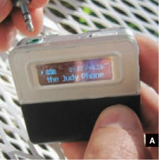
Fig. A: Copy your audio file to a small, cheap MP3 player.
1d. Load the MP3 file onto the player (it helps if the only file on the player is your Ghost Phone audio), set the player to permanent loop/repeat, press play, and you’re set.
2. Replace the speaker in the earpiece.
You don’t want to use the existing telephone speaker because speaker technology has advanced considerably over the past 10 or so years. Also, the analog telephone speaker’s impedance doesn’t match an MP3 player’s.
2a. After you remove the telephone’s earpiece, you’ll see that the speaker is screwed into the wiring by 2 spade lugs. Remove the screws and toss the speaker.
2b. Take the headphones that work with your MP3 player and break off 1 earpiece, keeping about 3" of the wire pair. Strip ½" of insulation from the end of each wire.
2c. Crimp 2 insulated female spade lugs onto the speaker wires (Figure B), then plug the male and female spade lugs together (Figure C). No bare wires should be visible. Check for shorts. Wrap it up with electrical tape.

Fig. B: Crimp 2 insulated female spade lugs onto the speaker wires.
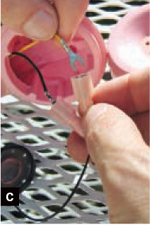
Fig. C: Plug the male and female spade lugs together.
3. Connect the audio plug to the telephone’s terminal strip.
3a. Take what remains of the broken headphones, and cut off the wires about 12" above the plug.
As you can see, the sleeve for the headphone wires contains 3 conductors: left, right, and common. You need to join the left and right wires.
To find out which is which, plug the audio plug into the MP3 player and join 2 of the 3 wires together. Take these 2 conductors and touch them to the speaker. If it plays, then permanently twist the wires together. If not, untwist and try another combination. Still not working? Untwist and try the third possible combination.
3b. Once you’ve figured out the wiring, crimp on male spade lugs.
3c. Take the cover off the phone and look for the main terminal strip. It’s under the handset cradle. I’m pointing to it with my favorite yellow screwdriver (Figure D).

Fig. D: Take the cover off the phone and look for the main terminal strip under the handset cradle.
NOTE: All phones are not the same, so some experimentation may be in order.
3d. To add realism, we want the voice to cut off when the handset is placed in the cradle. Trace the 4 wires from the handset (2 for the earpiece, 2 for the mouthpiece), down through the cradle switch and on to the main terminal strip.
You can use either a multimeter or trial and error: turn the MP3 player on, touch your 2 MP3 male lugs to the 4 handset wires on the main terminal strip, and listen for which 2 wires on the terminal strip are for the earpiece. Screw the lugs into the terminal strip.
3e. All that remains is to cut a hole (with a saw, Dremel, or metal shears) in the metal base of the phone so that the MP3 player can be hidden inside (Figure E). File down the sharp edges and cover the opening with duct tape.
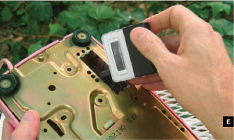
Fig. E: Cut a hole in the metal base of the phone so that the MP3 player can be hidden inside.
You’re done! The MP3 player should play through the earpiece when the handset’s lifted from the cradle.
Yes, the MP3 player must run constantly. It might be possible to connect a switch so that the player turns on when the handset is lifted from the cradle, or perhaps you can give the phone a remote switch. How about hooking up a motion sensor so that it automatically turns on when someone gets within proximity?
Another thing I like is to take the existing wall cord from the phone and rip and shred it about 12" from the phone itself. It makes it all a bit more mysterious. And I am all into mystery.
4. Create a scene.
Finally, since I’m into creating mysterious environments and making art projects far more interactive, I try to create scenes for the phones: a specific table that the phone rests on, appropriate props around it. Things that enhance and deepen the story of the ghost talking to you on the phone.
It’s more than just a phone with a dinky MP3 player inside. It’s a strange dream, shared. And it’s wonderful that I can share this one with you!
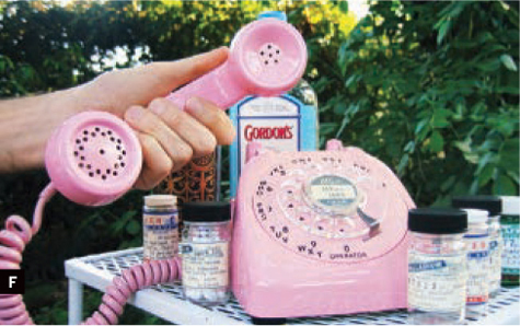
Fig F: Create a mysterious scene.
Greg MacLaurin (gregagogo.com) is an artist and concept designer in Los Angeles, whose work for Walt Disney Imagineering, Universal Creative, and other theme park design companies is challenging and fun, but is usually so secret he can never talk about it.
Photography by Frank E. Yost
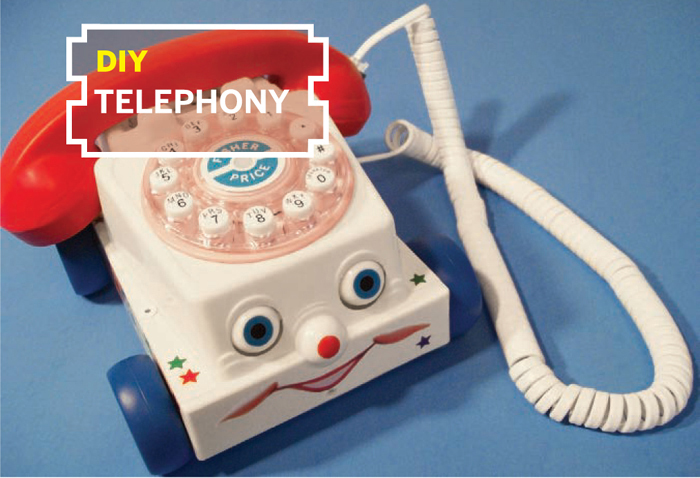
CHATTER TELEPHONE
Surprise! A classic pull-toy phone that really works.
I remember making pretend phone calls on my Fisher-Price Chatter Telephone when I was 7 or 8, and wondering if it was possible to turn it into a real phone. That question stayed with me, and when I saw a Chatter Telephone and a Crosley Princess Telephone recently at Target, I knew the answer was yes. I brought them home and made it work, and it was easier than I expected.
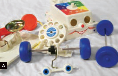
Disassembling the Chatter and Crosley phones was easy with screwdrivers (Figures A and B). The Chatter’s dial pops off when you tap out the pin underneath with a hammer and nail. To clear room inside the Chatter, I used a Dremel and X-Acto knife to shave the bell and clicker mounts off the inside of the bottom cover. Examining the phone’s workings, I saw that there were 6 elements I needed to fit into the Chatter. Here’s how I handled each.

Push-Button Dial
I used a paper template to mark and cut a 3" hole in the Chatter, centered over the dial’s sticker. The rest of the sticker I peeled off. I temporarily taped the Crosley dial in place in the 3" hole, turned it all upside down, and glued the dial in around its circumference. For reinforcement (optional), I Dremeled off the part of the Crosley’s shell that held the dial in back, filed its edges, and screwed it back on using the original screws (Figure C, page 156).
Fig. C: For reinforcement, use part of the Crosley’s shell and screw it back on using the original screws.
Later, I had to grind down the bottom inside edge of the dial, to give the Chatter’s eyes room to bob up and down. As a finishing touch, I removed the Fisher-Price sticker under a hair dryer, and affixed it to the new dial.
RJ11 Jacks
With a knife, I cut holes for the jacks in the Chatter’s base just next to the Fisher-Price logos on the right side and the back. Then I glued the jacks in place from the inside.
MATERIALS
Fisher-Price Classics Chatter Telephone about $15. The plastic ones have more room inside than the old wooden ones. I used the classic, boxy style (#952), now sold under license by Sababa Toys (sababatoys.com). This project might also work with the newer, rounded Fisher-Price model (#77816), but I didn’t try that one.
Crosley Princess Telephone $31 at Target
Simple used push-button telephone from a thrift store
Coiled telephone handset cord
Aluminum angle bar ½"×½"×1/16", scrap piece 8" long
20-gauge steel sheet, scrap piece ¾"×4"
Brass or steel pipe, ½"×4"
Plastic bolts with matching nuts, 3/4"×½" (4)
E-6000 glue not super glue
Red electrical tape I used Duck Brand 667 Pro Series.
Pop rivets, 1/8" aluminum, white
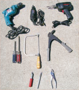
TOOLS
X-Acto knife
Pop-rivet gun
Soldering iron and solder
Screwdrivers: small Phillips and flat blade
Drill and drill bits: 1/16", 1/8", 7/16"
Dremel tool
Pliers
Coping saw aka hand jigsaw
File
Tinsnips
Drawing compass, paper, pencil, and scissors
Hammer and nail
Vise
Hair dryer
Hang-Up Hinge
The Crosley’s hang-up hinge is too long to tuck inside the Chatter, so I trimmed 11/8" off each end of the top piece and ¼" each from the bottom. I measured and drilled two 7/16" holes in the Chatter for the clear plastic plungers to stick up through (Figure D, next page). I then made a bracket out of sheet metal to hold the hinge underneath; download the pattern at makezine.com/16/diytelephony_chatter.

Fig. D: Cut holes in the Chatter phone’s cradle so the plungers can move up and down freely.
With the plungers through the new holes, I positioned the hinge and bracket so that the plungers moved up and down freely, and then I marked the bracket’s position, drilled four ¼" holes through the sides of the phone, and pop-riveted it in place.
Circuit Board
I made brackets for the circuit board out of aluminum angle; see makezine.com/16/diytelephony_chatter. I insulated them with electrical tape, screwed them to the board with 4 plastic nuts and bolts, and then drilled and popriveted them to the Chatter through the flat part of the base (Figure E).
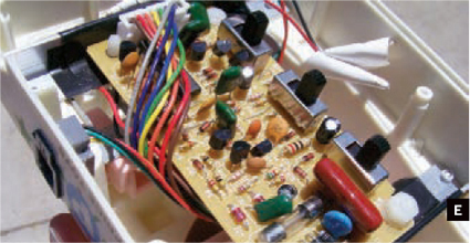
Fig. E: Make brackets for the circuit board, screw them to the board, and then pop-rivet them to the Chatter phone.
Bell
I put the bell on the outside of the Chatter phone by pop-riveting its mount across the sound vents in the back. The 2 wires powering the bell tucked neatly through one of the vents (Figure F).
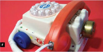
Fig. F: Put the bell on the outside of the Chatter phone by pop-riveting its mount in the back.
Handset
I assembled the handset last, after testing the modded body with a working donor handset. The Crosley’s handset had delicate wiring that melted under a soldering iron, so I used an older phone from a thrift store. I gutted the handset, cutting the wires to the microphone and speaker. Then I used a coping saw to cut off the Chatter handset’s caps, ½" from each end.
To add sufficient weight to push down the plungers, I hammered a 4" length of ¼" brass pipe into shape in a vise, threaded the curved pipe through the handle, and glued it in place. I cut out a hole for the jack, then fished the wiring through the pipe.
I drilled 1/16" sound holes through the end caps, following the toy’s existing dimple pattern, then glued in the microphone and speaker. I resoldered the wire connections, insulated them with tape, and glued the jack in place. Finally, I taped the caps back onto the handset tightly, using precisely cut red electrical tape that matched the toy almost perfectly (Figure F).
Conclusion
That’s how I turned a classic toy into a working telephone. Now call someone! With a phone like this, you’ll have plenty to talk about.
Frank E. Yost is an amateur artist who lives in Andover, Minn. He wrote the Retro R/C Racer project in MAKE, Volume 11.
Coloring Glue

When you’re about to glue up a crack repair or any other job where the glue will have to fill some gaps and be visible, don’t forget to add some color to the glue. It’s always better to have the glue line looking a bit darker than the surrounding wood, and the closer you match the color the better. Regular powdered artist’s pigments work well with most any glue, whether water soluble or catalyzed.
—Frank Ford, frets.com
Find more tools-n-tips at makezine.com/tnt.

Photography by Daniel Gentleman
CHUMBY PHONE
A hackable platform disguised as a red hotline.
There’s no simple explanation of the Chumby. It’s an alarm clock on steroids, a digital photo album, a tiny Linux box, an internet radio player, and more. Owners can set up a queue of personalized software widgets through which the Chumby continually cycles. These widgets, made interactive through the Chumby’s touchscreen and motion sensors, include news, weather, email notifications, Flickr feeds, Facebook friend status, and even Netflix queue status.
Above all, Chumby’s open design welcomes hacking and crafting. The creators of Chumby offer not only their entire base of source code, but the schematics to their hardware as well, at chumby.com/developers/hardware (login required).
With its “open everything” nature, the Chumby is easy to craft into a personal information appliance that can fit into any setting. In my case, this happens to be my computer desk, where I thought a bright red, 1980s-style telephone would look perfect.
Here’s how I repackaged my Chumby into an old desk phone, swapping its touchscreen for the phone’s original keypad, fitting its stereo speakers into each end of the phone’s handset, and putting its ports on the back, replacing the original RJ14 jack.
Chumby Inside Tour
The first step in crafting with the Chumby is learning the parts and how they all fit together. The leather case, slightly larger than a softball, has a 3" touchscreen face. The rear of the unit has a plastic assembly that houses a couple of USB ports, a headphone jack, and a pair of rear-facing speakers. On top of the Chumby, a single button under the leather toggles the control panel on and off.
Now for the inside tour. Open the unit by running a hobby knife or thin screwdriver between the plastic bezel and the leather case on the outside to release the glue. Peel back the case from the bezel, and the main assembly, known as the “core unit,” pops out. This core unit is attached to a 26-pin ribbon cable (the “Chumbilical”), so be gentle when removing it.
MATERIALS
Chumby
Desk phone
Workable material to make a small bracket Any kind of wood, metal, or plastic that you can size and shape will do. I used a spare, bendable metal belt from a VEX Robotics kit.
Mounting tape
26-pin 0.1"-spaced dual-row female connectors (2) from an electronics parts store
26-wire, 0.1"-spaced ribbon cable, 6" long You can use wider cable; I bought 32-wire cable and peeled away the excess.
Small panel-mount momentary push-button switch
Insulated hookup wire
TOOLS
Hobby knife
Thin screwdriver
Jigsaw or Dremel with cutting bits I used a Dremel, but jigsaw cuts would have been straighter.
Cardboard
Pencil or thin marker
Multimeter
Disconnect the Chumbilical from the core unit and remove all the stuffing inside, so you can access the rest of the components more easily (Figure A). The other end of this ribbon cable attaches to a small “daughtercard,” which carries the charger port, USB ports, headphone jack, on/off button connector, and a hidden 9-volt battery connector. Unscrew the 4 small screws that attach this daughtercard to the plastic at the rear of the Chumby, and remove the entire rear assembly.

Fig. A: Chumby dissected: the original leather case, the core unit, the rear unit with Chumbilical attached, and the cotton stuffing.
The core unit (Figure B) consists of 3 circuit boards. The main circuit board affixed to the LCD contains all the major electronics, including the CPU, memory, display controller, and a USB port that connects to the second board: the USB riser. The riser is a primarily blank board used to lift the third component, the USB wi-fi module, off the main circuitry. The USB riser’s empty back makes it a good surface for mounting additional hardware (Figure C).
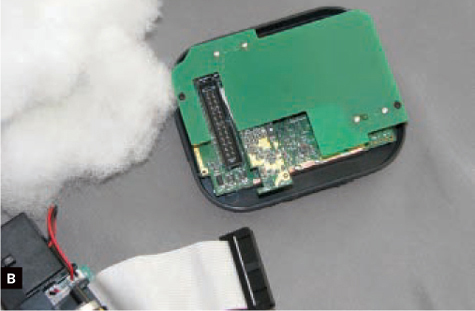
Fig. B: The core unit with the USB riser card in place.

Fig. C: The riser circuit board (lifted here) is a primarily blank board used to lift the third component, the USB wi-fi module, off the main circuitry.
Disassemble the Phone
Disassembling the donor phone was initially exciting but then somewhat heartbreaking, because these classic phones are such works of art on the inside.
After debating ways that I might attempt to reuse some of its components, I eventually decided to just gut the entire thing and only use its chassis, to make installation easier (Figure D).

Fig. D: The interior of the phone prior to gutting all the components.
Mount the Display
To hold the Chumby’s display up where the phone’s original keypad was located, I created a mounting bracket from a thin strap of metal, which I screwed into the phone’s bottom plate and bent up to the proper height and angle (Figure E).

Fig. E: Make a mounting bracket for the Chumby’s display from a thin strap of metal.
I first made a cardboard template by tracing lines around the keypad hole in the faceplate. Then I attached the metal band to the base with some of the phone’s original screws and, using the template as a guide, bent the band around to hold the Chumby’s touchscreen up where the original keypad sat. I affixed the touchscreen to its bracket with mounting tape, and fit the rest of the core unit underneath.
I used a Dremel with a cutting bit to cut a window for the Chumby’s screen in the phone’s faceplate. This is the most visible modification you’ll make, so take extra care in measuring, cutting, and finishing the square. I made a mistake when cutting one corner, and looking back, I wish I had used a jigsaw, but I used the blue “Chumby Charm” logo to successfully cover up the small misstep.
Extend the Chumbilical
The original Chumbilical is only a few inches long, and after mounting the display I realized I’d have to lengthen it if I wanted to put the Chumby’s ports on the back of the phone. Initially, I hoped that I could simply strip some of the ribbon cable’s wires, then solder leads connecting them to a new power plug, the USB riser, speakers, and switches. But from reading the schematics on the Chumby developer site, I learned that the daughtercard doesn’t just handle ports and power, it also carries a 3-axis motion detector that sends its readings to the main board so that software can react when the Chumby is tipped or shaken. It made more sense to extend everything.
To create a new Chumbilical, I went to my local electronics parts store and picked up a longer ribbon cable and 2 female 26-pin connectors, all for under $4. I crimped a connector to each end of the cable, making sure I had the header’s plastic notch and the red “pin 1” marking on the correct side each time. After closing the connectors down onto the ribbon cable, it’s a good idea to test for connectivity and short circuits using a multimeter and a needle. As a final step, fire up the Chumby and test the Chumbilical to make sure all functions still work.
Remove the Speakers and Daughtercard
Once the Chumbilical worked, I set forth dissecting the rear assembly of the Chumby. The daughtercard is only a few centimeters across and is affixed to the rear assembly with several screws.
The control panel button, 9V battery connector, and speaker wires are attached to the daughterboard with plastic connectors and headers, so I gently pulled them off; no desoldering necessary. Disconnecting these made the daughtercard slide easily out of the plastic assembly.
I measured the space on the daughtercard dedicated to the Chumby’s ports, and cut a matching hole in the back of the phone around its original RJ14 jack. Then I used mounting tape to affix the daughtercard to the inside of the phone case, with its ports and jacks facing out the hole.
The metal baseplate of the phone curves up around its perimeter, and its back edge covered the Chumby’s recessed power button, located at the bottom of its daughter card. I cut a notch in the metal to allow access to the button (Figure F, previous page). This lets you turn its power off and on with a pen or other small pointed object, which is the way you’d do it anyway; the Chumby is meant to be left on continuously.
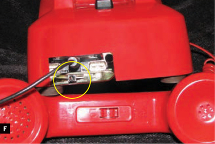
Fig. F: Cut a notch in the phone’s metal baseplate to allow access to the Chumby’s recessed power button.
Move the Speakers to the Phone Headset
Using a small screwdriver, I easily broke the brittle adhesive that attached the Chumby’s speakers to the rear assembly. To put them in the phone’s handset, I simply soldered some extension wires insulated with heat-shrink tubing to the RJ14 jacks at each end of the existing coiled phone cable. The cable has 4 wires, so it can drive 2 speakers.
The Chumby’s speaker wires are thick and easy to strip and solder, making them a good choice for hacking. Remembering to maintain the polarity, I soldered the pin connectors on the daughtercard for the speakers to the RJ14 jack contacts for the coil cable at the phone end. Then I unscrewed the microphone and speaker ends of the handset and simply lifted the 2 disk-shaped components out.
The Chumby’s speakers fit nicely at each end of the handset (Figure G). I wired them to the RJ14 jack on the bottom of the handset, and stuffed cotton around each speaker to prevent them from rattling against the plastic.
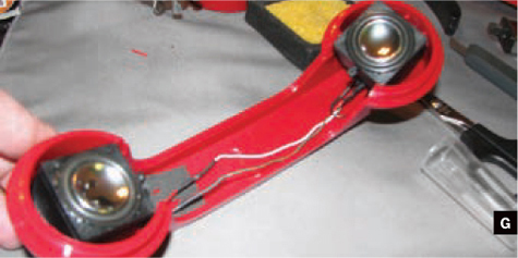
Fig. G: The Chumby’s speakers fit nicely at each end of the handset.
Mount the Control Panel Switch
The final step was to replace the control panel switch, the squeeze switch at the top of the Chumby. The original part is a limit switch with a long, curved arm. It fits well within the Chumby, but its large, exposed contacts would be easy to short-circuit, making it not very good for other projects.
The good news is that it’s simple to replace with any other type of intermittent contact switch. Initially, I wanted to set up my Chumby so the control panel switch would be triggered by the rocker that rotated when the phone was lifted from the hook. But my engineering skill failed me on this, forcing me to concede to a standard panel-mount pushbutton drilled in behind the handset cradle. Soldering the wires was easy, but now I have to disconnect that button whenever I open the phone chassis.
Future Improvements
While it’s not perfect, it is fun to have a big, retro, important-looking red phone that happens to run Linux, tune internet radio, and display widgets (Figure H). Since the Chumby’s schematics and source code are all available, all 3 of the following improvements should be relatively easy work.
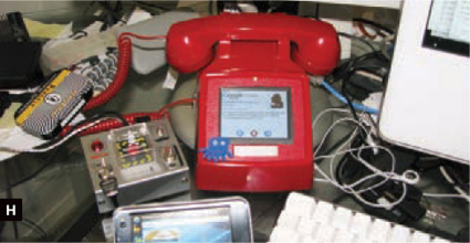
Fig. H: All done. It’s fun to have a big, retro, important-looking red phone that runs Linux, tunes internet radio, and displays web information widgets.
» Build an iPod dock into the back of the unit. Chumby can read from a USB-connected iPod (but not iPhone or iPod Touch), and it has a nice touchscreen interface for playing through the speakers.
» Improve access to the power button — likely by splicing out the Chumbilical’s leads for that contact.
» Connect a switch and hack software to activate the phone’s “hook” buttons. I eventually want the device to launch the internet radio application when you take the handset off the hook. Then, imagine hanging up the red phone and having internet radio automatically turn off. Sweet!
Daniel Gentleman ([email protected]), better known as ThoughtFix, operates two blogs about mobile technology and portable Linux devices.