
THE Teacup Stirling Engine
Turn the heat from tea, coffee, or candles into piston power!

Photography by Sam Murphy
![]() To see a video of a Teacup Stirling Engine being built and run, check out: makezine.com/17/stirling
To see a video of a Teacup Stirling Engine being built and run, check out: makezine.com/17/stirling
There’s energy all around us, just waiting to be tapped. Whether it’s a hot cup of coffee on a cold day, light from the sun, scented candles, or waste heat wafting from electronics, it’s all potential power waiting to be harnessed! This is the world of the Stirling engine.
Have you ever tried this fun experiment? Put a tightly filled balloon in the freezer. When you return, you’ll find it shrunken. Bring it out into the warm room again and it will expand!
What if we could use these expanding and contracting states to move a piston? This is the principle behind the Stirling engine, invented and patented by the Reverend Doctor Robert Stirling, in 1816. It’s a simple idea, for a very simple engine. Let’s build one!
Jim Shealy is a 17-year-old who enjoys building engines. He’s built everything from pulse jets to turbines, and is currently enrolled at Georgia Tech.
MATERIALS
CD or large plastic jar lid such as a peanut butter lid
10"×5" piece of aluminum or steel plate, at least 1/16" thick Two 5"×5" pieces are fine.
Plastic CD spindle case from a stack of blank CDs
Wire rod, 1/8" steel or 1/16" stainless steel Welding rod is preferred, and stainless steel is best; it must be smooth and straight!
¾" PVC pipe, 7" length
10"×5" piece of foam board or two 5"×5" pieces
¾" copper pipe
1" length of any type of pipe, C-stock, or L-angle stock Epoxies: J-B Weld or J-B Kwik, and cheap 5- or 15-minute epoxy If it says “non-shrink,” don’t get it!
Hot glue gun and glue (optional)
Fan weights or pennies (optional)
Double-sided tape (optional)
TOOLS
Hacksaw
Utility knife
Drawing compass
Ruler
Marker
Electrical tape or glue
Drill and drill bits: 1/16" or 1/8", 5/32", ½"–¾"
Needlenose pliers (2 pairs)
Wire cutters
Hair dryer
Plastic cling wrap
Window cleaner
Cooking spray
Before starting, read the tips on page 75 so you know what you’re getting into.
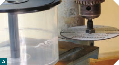
1. Cut the displacer ring.
Mark a CD spindle case 1" below the top, all the way around. You can fill it with CDs up to your mark and use them as a guide. Remove the CDs and cut the case in two, along your mark. I used a drill press and cutoff wheel and made a level cut by spinning the case (Figure A, following page). A hacksaw works, too. Next, cut the top off the case, leaving a ring.
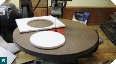
2. Make the displacer.
Using the cut top of the CD case as a guide, span your compass from the center of the case to ¼" from the edge — 2¼" in my case.
Draw 2 circles with this radius on your foam board (make sure to mark the center points!). Cut them out roughly, then use a jigsaw, foam cutter, or utility knife to finish the cuts (Figure B).
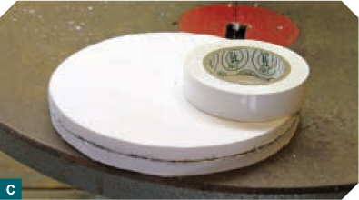
Stack the 2 circles, then tape or glue them together around their circumference. I used white electrical tape (Figure C).
3. Cut the aluminum hot and cold plates.
Draw two 5" circles on your aluminum stock. These are the top and bottom plates (cold and hot, respectively) that power your engine. Use a hacksaw or band saw, take it slow, and cut out the circles (Figures D and E). They don’t have to be perfect; just make sure they cover the displacer ring completely.

Photography by Jim Shealy (A–C, G, H) and Ed Troxell (D–F)

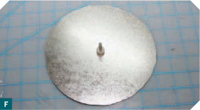
4. Drill the top plate to fit the rod.
Here’s where problems can arise — not critical ones, but extremely annoying ones. Using your small drill bit (the one that matches the diameter rod you’re using, in my case 1/16"), drill through the exact center of 1 plate (Figure F). This will be your top/cold plate.
Test-fit the rod in the hole and make sure it’s a smooth fit. In order to maintain thermal efficiency, we need this passage to be as airtight as possible, but still allow the rod to run smoothly in and out of the plate. If you wiggle the wire around, you may notice that it tends to stick at any angle. Keep it perpendicular to the plates.
If the rod isn’t running smoothly, try this: Run the bit through the hole again to make sure it’s clear.
File or sand down the edge of the wire rod to make sure it’s not causing any binding. If it still doesn’t fit, try wiggling the plate around a bit to widen the hole.
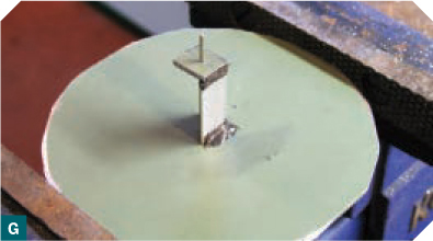
5. Build the top plate standoff.
Once the rod runs smoothly, cut a 1" piece of pipe, C-stock, or angle stock (I’ve used both angle stock and pipe for this), and cut a small square (or circle, if you’re using pipe) of metal from the scraps you cut while making your plates. Drill a hole in the exact center of the small square (or circle). This will act as a standoff to keep the displacer rod perpendicular to the plates.
Center the piece of angle stock (or pipe) over the hole and glue it down to the top plate with epoxy (Figure G). Poke the wire rod through the holes in the plate and the standoff, making sure it slides smoothly, and glue the standoff to the angle piece. As the epoxy cures, check periodically that the rod still moves freely in the hole, and adjust if necessary. If the rod “freezes,” redrill the top hole with the next-larger bit.
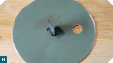
Finally, near the edge of the top plate drill a ½"–¾" hole (Figure H). Bigger is better, but just make sure the pipe you’re using for the piston cylinder is slightly bigger than this hole (the pipe should not fit inside this hole).
NOTE: For the best piston-casting results, don’t mix the epoxy in the cylinder. The oil seems to contaminate it and keeps it from hardening. Mix on wax paper or plastic wrap. Don’t use 1-minute epoxy; it can shrink too much or get too hot. Also, don’t use extra-time epoxy; it probably won’t shrink enough.
6. Cast the piston.
I’ve tried using nearly everything under the sun as a piston. Nothing worked. Without machining one, you’re left with few options. So, we’ll cast a piston.
6a. Cut 3" of copper pipe; this will be your cylinder. Deburr the inside edge with a utility knife. Don’t use sandpaper; you’re smoothing the pipe so you can push out the cast piston. Clean the inside until it’s nice and shiny. Window cleaner helps.
6b. Wrap the base of the pipe with plastic wrap and secure with a rubber band. Then oil the inside of the pipe (Figure I, next page). Cooking spray works fine.

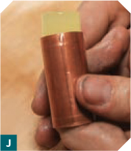
6c. Pre-warm your 15-minute epoxy components using a hair dryer. You want it nice and runny. Mix enough epoxy to fill ½" of the pipe or so. Fill the pipe. Once the epoxy is fully cured, remove the plastic wrap. Your cast piston should push right out (Figure J). Before you push it all the way out, mark the piston and cylinder so you can match them exactly later (see tip on page 72).
6d. Cut 1" of wire and bend the end into a hook. Drill a hole in the center of the piston and glue the hook in place (Figure K).

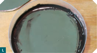
While you’re waiting for the piston to cure, use J-B Weld or J-B Kwik to glue your plastic displacer ring to the bottom metal plate (Figure L).
7. Make the displacer rod and 2 lever arms.
Here’s a critical step: correctly bending the wire rods. Take some more wire and bend a hook in 1 end. Cut the other end at about 5". This is your displacer rod (Figure M). Sand the end and make sure it fits through the hole in the aluminum top plate. Fill the hook with epoxy (Figure N). Go ahead and fill the piston hook, too.


Photography by Jim Shealy (L, P, Q) and Ed Troxell
To cut the displacer rod to length, first lay the top plate on top of the bottom displacer assembly that you glued, so that its small center hole hangs over one edge. Put the 5" displacer rod through the holes until its hook is resting on the standoff. Mark where the rod meets the edge of the bottom plate. Remove the rod and cut it where you marked.
Now create the 2 lever arm rods. Bend a hook onto a length of wire, mark the wire 2" from the base of the hook, then cut it 2½" from the base of the hook (½" from your mark).
At your mark, bend a 90° angle, then bend a bit of the end as well (to keep the piston and displacer rod hooks from sliding off). Make another rod in the same fashion (Figure O).

Fill the hooks on the lever rods with epoxy as you did on the previous 2 hooks.
8. Mount the piston cylinder.
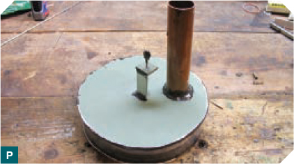
Again, clean the inside of your copper cylinder very well. Center it over the large hole you drilled on the top plate and epoxy it in place (Figure P).
Once cured, wipe the inside of the pipe with an oiled towel. Test the piston in it. Align the marks on the piston and cylinder, then move the piston up and down until it travels freely in the cylinder.
TIP: The inside of a copper pipe is extruded, meaning it has small ridges that run its length. These need to be matched with your piston, which was cast with these ridges as well. Just move the piston up and down, slowly twisting until it moves freely.
9. Bend the crankshaft.
The crankshaft is probably the most critical part of your engine. It must be as straight as possible, and its 2 cams must not be too deep. Its piston cam must be 0.15"–0.20" deep, and its displacer cam must be a little less than 0.25" deep.
Also, the cams need to be 90° out of phase from each other: if one is lying flat on the workbench, the other should be standing straight up. You probably won’t get it right the first time, so don’t sweat it.
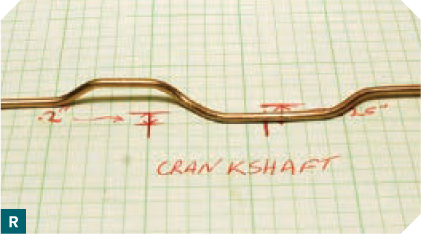
Measure the distance between the piston rod and displacer rod (Figure Q) and mark their locations on a sheet of paper; these indicate where the cams will go (Figure R).

Photography by Jim Shealy
NOTE: You can also use a CD for a flywheel. Just mold an epoxy disk in the center, and drill out an attachment hole.
Cut an 8" length of rod. Bend the first cam, using both sets of pliers to hold and shape the wire. Bend the second cam offset 90° from the first. Make sure the wire still lies flat and the cams are where you want them after bending. Roll the wire to make sure it’s still straight, and straighten it if necessary.
NOTE: The cams can be bent in trapezoidal shapes rather than rectangles.
10. Glue up the displacer and the crankshaft.
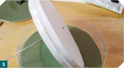
Drill a 3/32" hole (or one size bigger than your wire) in the center of each epoxied rod hook. Put the displacer rod through the standoff and center hole again. Drill (or poke) the rod into the exact center of the foam board displacer disks and epoxy it in place (Figure S). Make sure it’s attached really well. It’s a royal pain if it falls off after you’ve glued the displacer assembly together. Now glue the top plate onto the displacer ring. I suggest using hot glue. (Don’t use hot glue on the bottom plate, as it will melt during operation of the engine.)
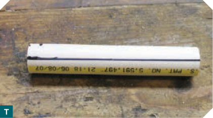
Cut a 5" length of PVC pipe, then cut it in half lengthwise (Figure T). These pieces become our crankshaft stands to hold the crankshaft and flywheel in place. Measure how high the shaft will need to be — so that when the displacer rod is raised halfway, the lever rod hole is level with the shaft — and drill a hole in each stand at that height. I’d suggest drilling holes just above and below this one, just in case the height of the crankshaft needs to be adjusted during engine tuning.
Finally, epoxy one crankshaft stand right behind the piston cylinder, lined up with the piston and displacer rods. Don’t glue the opposite crankshaft stand in place yet!
11. Final assembly and testing.
Attach the piston to its lever arm, and slide the lever arm into position on the crankshaft. It’ll take some wiggling. Slide the crankshaft through the middle hole on the crankshaft stand you glued down. Next, slide the lever arm for the displacer rod onto the crankshaft, and attach it to the displacer rod (you may need to bend the bottom hook). Slide the second crankshaft stand onto the shaft and line it up. We still don’t want to glue it in place until we’re done tuning the engine.
Turn the crankshaft. Does anything hang up? If the piston isn’t pumping properly, is it lined up where you marked it? If not, remove it and twist the lever arm until it lines up.
When turning the rod, can you complete a full rotation? If not, check the displacer disk. Does it move all the way up and down? If it’s trying to go too high, move the crankshaft down 1 hole on the stand. If too low, raise it 1 hole. If it doesn’t make a complete turn because it’s trying to go too high and too low, bend shallower cams on the crankshaft. Bend deeper cams if there’s too much of a gap.
If it turns over nicely, drill a hole the same size as your rod in the center of your peanut butter lid. This is your flywheel. Push it onto the end of the crankshaft closest to the piston cylinder. It should be a snug fit. Don’t glue it yet.
Now, the moment of truth. Apply heat to the bottom of the displacer assembly. Does it work? Try different heat sources: hot tea, coffee, votive candles, a tin filled with alcohol. Obviously, don’t melt the plastic displacer ring with too much heat. Turn the shaft and see what happens. One direction should be significantly easier than the other; this is the way your engine runs. After the metal heats for a bit, your engine will either not run at all, or it will kind of move but the piston won’t move as high and low as it could. Or it’ll run perfectly.
If performance is sluggish, make sure all your glue joints are airtight. Also, make sure nothing is snagging or hanging up. Add oil to the moving parts and try again. And finally, try making the piston’s cam shallower. You can also put ice cubes on the cold plate to increase the temperature differential.
Tune It
It works! Basically, you’re done, but let’s tune things up a bit. Check for these problems: friction, hangups, overstressed parts (trying to make them do more than they want to do), and leaks.
Add oil where needed (not much), adjust any parts causing problems, and keep everything sealed tight. Also, you need to counterbalance the displacer. First, glue the second crankshaft stand down, and glue the flywheel to the crankshaft. Get your fan weights (or pennies) and stick them to various spots on the wheel (use double-stick tape) until you find the right spots that offer the best performance (Figure U).

You’re done! Steampunks, start your engines!
How It Works
Start off by pushing the air into the hot side of your engine, by spinning the flywheel to raise the displacer.
1. The air is heated and expands, raising the pressure inside the engine and forcing the piston upward (a stroke).
2. The displacer falls, moving the air to the cold side.
3. The air is cooled and contracts, lowering the pressure in the engine and sucking the piston back downward (a stroke).
4. The displacer rises, moving the air back to the hot side again.
And the cycle repeats. The displacer isn’t really doing any work, it’s just taking up space to move the air to one side or the other, so that the heating and cooling can do the work.
PARTS OF THE TEACUP STIRLING ENGINE:
➊ Crankshaft
➋ Crankshaft stand
➌ Displacer lever rod, and beneath it the displacer rod
➍ Piston lever rod
➎ Displacer rod standoff
➏ Piston cylinder (with piston inside)
➐ Flywheel
➑ Top displacer plate (cold side)
➒ Displacer ring (with foam displacer disk inside)
➓ Bottom displacer plate (hot side)

Illustration by Damien Scogin
Building and Operating Tips
Building a Stirling engine can be a real challenge. If you undertake this project, take your time. Be patient. Go over all instructions carefully, watch the video, and read the discussion of the Instructables version (makezine.com/go/stirling) before you start work. Here are some tips to increase your chance of success:
» The piston can be difficult to cast. Don’t try mixing the epoxy in the cylinder. Mix it outside, then pour it in. It may take several attempts.
» Grease the cylinder before casting.
» The piston should fit snugly in the cylinder but not too tightly, and should not slide loosely. Remember, the copper pipe has casting grooves in it that the cast piston must travel in.
» Leaks are your enemy. Make sure everything — the displacer chamber, the piston cylinder — is as airtight as possible.
» Friction is your other enemy. Make sure the crankshaft and lever rods travel as smoothly and frictionlessly as possible.
» You want the 2 displacer plates to have the greatest possible temperature differential (around 200°F). Try putting ice on the cold plate.
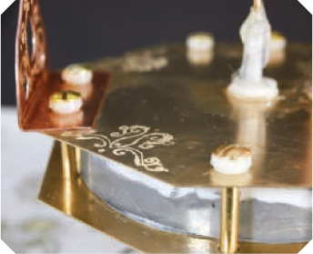
NOTE: The photos on pages 68 and 69 are for illustration purposes only, to show how you can decorate your engine to make it look more old-school. The brass rods connecting the top and bottom displacer plates are probably not a good idea, unless they’re completely insulated to prevent heat transfer.
A version of this project was originally posted on instructables.com.