THE BEATBEARING TANGIBLE RHYTHM SEQUENCER

Photography by Peter Bennett
STEEL PULSE
The BeatBearing is an exciting and intuitive way to make music. Move the balls on a grid, and you change the beat. Music sequencing couldn’t be simpler.
Like countless other musicians, I use a computer to create beats and sequence them into mixes. Pointing and clicking with a mouse is fine for a studio, but what about when you want to sequence rhythms in live performance? Or collaborate with others on a shared rhythm? These questions led me to develop the BeatBearing sequencer.
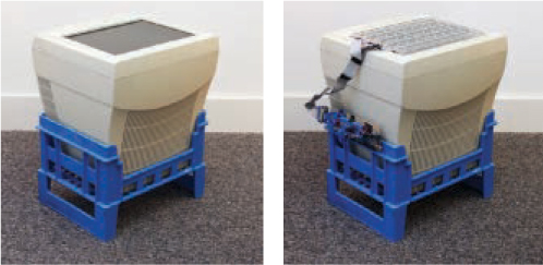
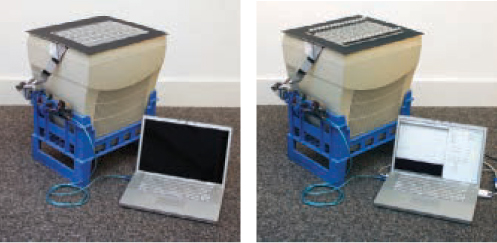
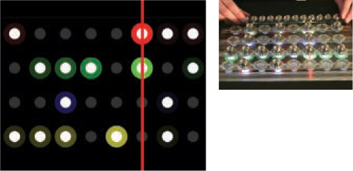
So what is the BeatBearing? Simply put, it’s a computer interface that takes the pattern of ball bearings placed on a grid and translates it into a rhythm. The fun part is that the whole interface is transparent and sits on top of a computer screen, allowing graphics to be shown from directly underneath. The screen highlights which beats are switched on, and what sounds they’re playing, as a red line sweeps across the screen to show the current time position. The system is controlled by an Arduino microcontroller, and the screen is an old computer monitor cradled in a milk crate.
Set up: p.123 Make it: p.124 Use it: p.129
Peter Bennett ([email protected]) is a Ph.D. student in the Sonic Arts Research Centre at Queen’s University Belfast in Northern Ireland, where he’s researching the design of digital musical instruments. He has previously studied cybernetics, digital-media art, and design, while maintaining a constant interest in musical performance and composition.
MAKING BEATS WITH BALLS
The BeatBearing plays rhythms based on ball bearing placement.
➊ A 4×8 grid of transparent plastic acts as a control surface. The horizontal positions define a repeating musical measure with 8 beats, while the vertical positions carry 4 different preprogrammed drum sounds that you can trigger at each beat.
➋ The visualizer on the flat-screen CRT monitor shows which bearings are active and where the current beat is in the 8-beat sequence.
➌ A cache in the plastic base grid holds unused ball bearings.
➍ A plastic crate acts as a handy cradle for the monitor.

Illustration by Tim Lillis
➎ A steel ball bearing in any grid position closes the electrical connection between the 2 halves of a split metal washer underneath.
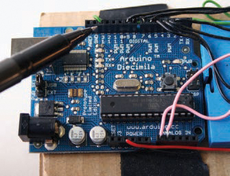
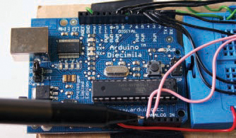
➏ An Arduino microcontroller collects the ball/no ball states of each of the 32 washers and continuously sends this information to a laptop computer via USB cable.
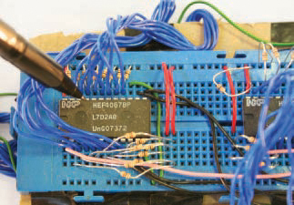
➐ Two multiplexer chips let the Arduino read values from all 32 washer switches, receiving them in sequence through 2 analog input pins.
➑ A laptop computer takes the rhythm feed from the Arduino and translates it simultaneously into both MIDI sound data and visuals for display on the screen underneath the grid. The laptop also runs standard software to convert the MIDI into sound.
SET UP.
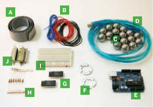
MATERIALS
[A] 20-wire ribbon cable about 2 meters long, or two 40-wire IDE cables, one with a connector in the center.
[B] Insulated solid-core hookup wire in 3 colors to help differentiate ground, power, and signal lines
[C] Ball bearings (32) Mine were 20mm. Use chrome-plated, or they will rust.
[D] USB cable
[E] Arduino Diecimilia microcontroller board It’s available from makershed.com. The new Duemilanove board should also work.
[F] Washers (32) to comfortably seat ball bearings; mine were 30mm outer diameter (OD), 17mm inner diameter (ID).
[G] Multiplexer chips, NXP (Philips) HEF4067B (2)
[H] 10kΩ resistors (32)
[I] Solderless breadboard
[J] D-sub (25-pin) connectors, matching male/female pairs (2) Make sure they fit together, that one has solderable pins, and that the other can crimp a ribbon cable. If you’re using IDE cables, you’ll need three 2×20 male headers to fit.
[NOT SHOWN]
Laptop computer The project software is written both in Processing and on the Arduino, so it’s cross-platform.
Flat-screen CRT monitor You can get one cheap or even free these days. Make sure the screen isn’t curved!
Solid sheet of transparent acrylic (plexiglass) or polycarbonate cut to the dimensions of the CRT monitor screen. I used 15mm thick.
Screws and matching nuts (64) Size the screws so they fit through small holes drilled in the washers and pass through the clear plastic sheet; I used M2 (2mm diameter).
Solder tabs (64) One end is a flat tab for soldering onto; the other has a hole that should fit the screws.
Scrap corrugated cardboard around 10cm×25cm
Duct tape
Plastic milk crate or some other way to hold the monitor horizontal. Improvise, or construct a simple frame from wood.
Black poster board cut to the dimensions of the CRT monitor screen
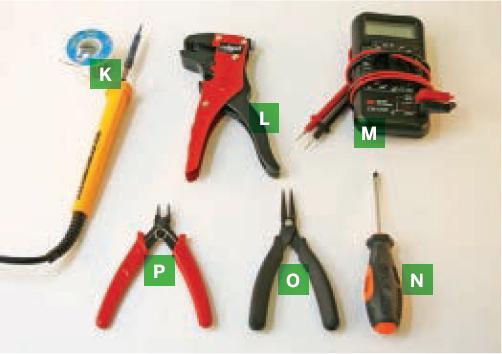
TOOLS
[K] Soldering iron and solder
[L] Wire stripper
[M] Multimeter for checking connections
[N] Screwdriver
[O] Needlenose pliers
[P] Wire cutters
[NOT SHOWN]
Band saw
Vise
Drill press and drill bit to match the screw size, in my case 2mm
Metal file
Router
Milling machine (optional) replaces the 5 tools preceding if you have access to a friendly engineering department
Ruler and straightedge
Clear glue and 5mm transparent plastic (optional) instead of the ruler and straightedge. Same type of plastic as the 15mm sheet above.
MAKE IT.

BUILD YOUR OWN BEATBEARING TANGIBLE SEQUENCER
Time: Couple of Weekends Complexity: Moderate
START ≫
1. SPLIT THE WASHERS
I had these washers split and drilled by a milling machine at Queens University Belfast’s friendly engineering department, but you can achieve similar results using a band saw and a drill press as follows. Alternatively, you can bypass the washers altogether and make ball-bearing contact switches more easily out of bent wire, or with screws or metal pins arranged in a triangle or square. See makezine.com/17/beatbearing for sketches.
1a. Clamp and drill the washers in a drill press, centering the 2 small holes on opposite sides of each.
1b. Use a band saw to cut each washer in half, perpendicular to the axis formed by the 2 holes. It’s easier if you clamp or screw the washer to a jig of scrap metal or wood.
1c. File off any sharp edges. The washers will be exposed to fingers when installed on the instrument.

2. CONSTRUCT THE TRANSPARENT BASE
Like the washers, the base can be CNC-milled or made by hand. Mine was milled; I sent a CAD file to the QUB engineering department to manufacture (see the plan at makezine.com/17/beatbearing). You can also drill and rout the base as described here, or else bypass the machining entirely by gluing thin horizontal strips of plastic to elevate the washers and make channels for the wires and spare bearings.

2a. Cut the transparent acrylic sheet to just cover your CRT screen.
2b. For each washer, following a regular 4×8 grid, drill a hole through the plastic sheet to match the washers’ inside diameter.
2c. Countersink another straight-sided hole for each washer that fits its outer diameter and thickness, so the washers will sit flush with the surface of the plastic.
2d. Drill 2 more holes through the plastic for each washer, positioned to align with its screw holes.
2e. On the underside of the base, cut straight channels about 5mm deep running horizontally through each row of holes for the wires. If you’re drilling by hand, use a router along a straightedge fence.

2f. Cut 2 more horizontal channels on the topside of the base, along the top and bottom. These channels will house balls that aren’t currently in use.

2g. Attach the washer halves to the transparent base using screws, holding 1 solder tab above each nut on the underside.
3. WIRE THE BASE
3a. Cut the ribbon cable in 2. With each half, carefully peel the red wire along one side away from the rest of the cable, separating it down to a length matching the grid’s width. These will be the ground wires. With 40-wire IDE cable, just use 1 cable.
3b. One side of each washer connects to ground, so run the ground wires from the ribbons down 2 of the rows, soldering each wire to the tabs on all washer halves facing the same way. For the other 2 rows, cut some spare wire and solder it to the remaining ground tabs and to the ground wire.

3c. For each row, peel away and solder 8 more ribbon wires to the other washer halves, trimming them progressively shorter. Each ribbon will have 3 wire connections unused.

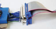
3d. Crimp a D-sub connector onto the other ends of each ribbon, lining them up so that the teeth engage properly with the wires inside. These connectors let you disconnect the grid base from the rest of the electronics.
4. BUILD THE ELECTRONICS
NOTE: For all wiring, follow the schematic at makezine.com/17/beatbearing.
4a. Solder wires about 10cm long to the 2 solderable D-sub connectors. Use a contrasting color for the ground wires, and don’t bother with the 4 unused pins.
NOTE: With IDE cables, you don’t need to solder. Plug the 3-connector cable’s center connector and one end connector on opposite sides of the breadboard trench, offset by 1 hole (see diagram online).
4b. Connect the 4 ground wires from the D-sub connectors to 1 edge of the solderless breadboard, establishing a ground rail. Use another wire to connect this rail to the Arduino’s ground terminal. To hold the breadboard next to the Arduino, I taped both to a piece of cardboard.
4c. Connect the 5V line of the Arduino to the breadboard along the opposite side from the ground, creating a 5V rail.
4d. Plug the 2 multiplexer chips across the breadboard’s central trench and connect them up to the switch wires from the D-sub connectors. With HEF4067B chips, the 16 independent inputs Y0–Y15 run from pin 2 to pin 9 on one side and from pin 16 to pin 23 on the other. Don’t worry about the order; comments in the software explain how to sequence the washer inputs there, which is easier than untangling and continuity-testing all the wires.
4e. Connect each multiplexer’s 4 address pins (pins 10, 11, 13, and 14) to 4 of the Arduino’s digital input/output pins. These let the Arduino select which multiplexer input to receive as analog input. Here again, you can designate the sequence later in the software.
4f. Wire each multiplexer’s common input/output Z (pin 1) to one of the analog inputs on the Arduino, A0–A1. Using the analog inputs lets you select the threshold voltage at which the switch is triggered in the firmware. You could use the digital inputs instead for greater speed, but you’d lose the ability to change the threshold.
4g. Connect a 10kΩ pull-up resistor from each multiplexer input up to the 5V rail. This ties all the inputs to the 5V line and prevents them from having a floating signal. When a ball bearing is placed on a washer, the circuit is closed and the input voltage is pulled down to ground.
5. ASSEMBLE THE HARDWARE
5a. Lay the monitor on its back in the milk crate, or anything else that will cradle it and keep it stable.
5b. Place the transparent base on top of the screen, and attach the electronics using the D-sub connectors. I taped the electronics to the side of the crate to keep them off the floor.
5c. Size and cut a frame of black poster board to disguise the CRT screen and hide the ribbon cables. (An ideal solution would be to build the screen into a table or cabinet.)
5d. Connect your laptop to the monitor, and to the Arduino via USB cable.
6. INSTALL THE SOFTWARE
6a. Download and install the Arduino programming environment from arduino.cc and the BeatBearing project bundle from makezine.com/17/beatbearing. Launch the programming environment.
6b. Copy and paste the BeatBearing Arduino code into a new Arduino document, then save.
6c. Select Arduino Diecimilia from the Tools ⇒ Board menu, then click File ⇒ Upload to I/O Board. A message should appear in the comments pane at the bottom confirming that the board was successfully programmed.
6d. Download and install Processing from processing.org. The BeatBearing software was created in version 135; it should work fine with the latest version, but if you have problems, switch to version 135.
6e. Download and install the ProMIDI library for Processing from texone.org/promidi and the trial version of Ableton Live or Live LE from ableton.com.
6f. From Processing, open the BeatBearing Processing program, included in the project bundle. This application reads the position of the bells, then creates the MIDI messages and visuals.
6g. Launch Ableton Live (or another MIDI program or soft-synth) to generate the sound output. The free trial version of Live won’t let you save settings, but you don’t need this to run BeatBearing. On a Mac, configure the program to receive MIDI from Processing via the built-in IAC bus (inter-application communication). With Windows you should be able to route the MIDI using Virtual Audio Cable (ntonyx.com/vac.htm), although I haven’t tried this.
6h. From your laptop’s display configuration pane, change the second screen’s resolution to 640×480, and position it to the left of the primary screen and lined up at the top.
6i. Run the Processing program. No error messages should appear, and the monitor should turn black with an array of gray dots and a sweeping red line. If the monitor turns gray, then Processing might not be connecting to the board. In this case, check that all other Processing applications (shown as applets in the dock) are closed and then re-plug the board in and try again!
6j. The Beatbearing Processing code may need some tweaking to get things right, such as lining up the virtual grid with the real grid. The code has been commented to make modifications as easy as possible — the only limit is your imagination!
FINISH X
NOW GO USE IT »
USE IT.

DROP SOME BEATS
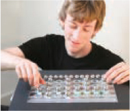
The BeatBearing is simple to use. Simply place a ball in a hole to start triggering a sound at that position. Remove it to switch the sound out.
TANGIBLE USER INTERFACES
I first encountered tangible user interfaces (TUIs) at the Ars Electronica exhibition in 2003, where I saw James Patten’s Audiopad project and Sony CSL’s Block Jam. These TUIs, along with others I have since found, inspired me to pursue a Ph.D. to study and develop new musical instruments, and influenced my design for the BeatBearing.
The main idea behind TUI design is that the user should be given a physical handle on the digital data. Importantly, this handle should allow the user not only to feel and see the data, but also to grasp and manipulate it. In the case of the BeatBearing, you “read” and manipulate the sequencer through the arrangement of the balls.
One design challenge I’ve found with TUIs is how to include a visual display. Typical computer game interfaces (and others) have you look at the screen while manipulating a controller elsewhere. Many TUI researchers create more direct connections by projecting an image onto a control surface from above or below. I’ve tried top-projection with instruments I’ve designed, but found it cumbersome, especially if you want a portable instrument for playing live. My solution for the BeatBearing was to ditch the expensive digital projector and show the visuals from below using a cheaper CRT.
I deliberately designed this project to be a base upon which further tangible interfaces could be developed. I believe it has the potential to do much more than this original version.
MODIFICATIONS
Each part of the BeatBearing is simple enough to allow for easy modification. Here are some ideas:
» Tweak the Processing code to change the graphics. How about showing the name of each sample?
» Add a tempo control in the software, or add a dedicated potentiometer to the hardware.
» Build the BeatBearing into a coffee table, wooden cabinet, or my favorite, an old leather briefcase.
» Add extra “sample select” holes to one side of the grid, allowing you to switch between sample banks directly from the board.
» Expand the grid. A 16×4 grid would be large enough to create more serious rhythms.
» Use a flat LCD monitor instead of the bulky CRT — a bit more expensive, but much more portable.
» Write new software. You can use the program provided, but if you want to develop your own firmware, the pseudo-code is:
a. Set address lines on the multiplexers.
b. Read analog pins.
c. Repeat Steps a and b to read all the positions on the grid (cycling from 0000 to 1111).
d. Send out the values of all grid positions over serial.
Different software applications are possible; for example, rather than a sequencer, how about a real-time performance instrument?
Resources
Peter Bennett’s home page with BeatBearing news: www.sarc.qub.ac.uk/~pbennett
![]() BeatBearing demo video on YouTube: makezine.com/go/beatbearing
BeatBearing demo video on YouTube: makezine.com/go/beatbearing
![]() Visit makezine.com/17/beatbearing for BeatBearing code, diagrams, sketches, and links to other resources and inspirations.
Visit makezine.com/17/beatbearing for BeatBearing code, diagrams, sketches, and links to other resources and inspirations.