

Photograph by Matt Blum

ELASTIC STRING BASS
Optically amplified rubber band twang.
I’m always inventing new demonstrations for school. To show how inductive pickups work, I once built a comically large guitar that I strung with steel cable. Later I decided that optical sensing is more versatile, since it works with strings made from any material, and it’s also actually easier.
So I came up with this rubber-band bass. Plug it into a standard guitar or bass amplifier, and you can play amazingly low frequencies and cool sounds. Each rubber band sits between a paired infrared LED and receiver, and as it vibrates, it varies the amount of light detected. Each string’s signal is then amplified and mixed with the signals from other strings.
Rubber bands sound very different from steel or nylon strings. Their tone is rich in harmonics, and the high frequencies damp out fast. Rubber’s high elasticity also means you can generate unusually low notes out of short lengths of band.
Because the amplifier requires both positive and negative voltages, I power the guitar using two 9V batteries, which are switched with a single dual-pole toggle. A red LED indicates when power is on.
My original version had 4 elastic bands, one much longer than the rest. For simplicity, this article shows how to build a single-string version, which you can easily extend to accommodate multiple strings.
1. Plan the overall layout.
Figure out how you’ll fit the circuit board, components, and batteries into your guitar body (Figure A, page 139). My sandwich maker’s interior measured 4"×4"× 1¼", so I had to trim the board a bit (Figure B). I used a saw, but you can also score a line with a file or Dremel and snap the board along the line. If you’re building your own guitar body, leave extra room for wires and components; it’s easy to underestimate.
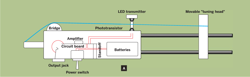
Fig. A: Functional overview of the optical guitar.

Fig. B: Lay out components and trim the protoboard as needed to fit in your guitar body.
MATERIALS
Resistors, 1/8 watt: 100kΩ (2 per string), 1kΩ (1 per string), 440Ω
1μF capacitors, ceramic, not polarized (1 per string, +1)
741 op-amp chip, DIP style RadioShack part #276-007
T-1¾ (5mm) red LED
T-1¾ (5mm) infrared LED (emitter) and phototransistor (detector) RadioShack #276-143 and #276-145, or Jameco #106526 and #112169. You can also buy a matched pair, RadioShack #276-142.
22-gauge solid-core insulated wire
Prototyping PC board RadioShack #276-150
8-pin DIP socket RadioShack #276-1995
1MΩ or 100kΩ trim potentiometer preferably 1M, to allow wider output range adjustment
Dual-pole toggle switch, DPDT or DPST
¼" female audio output jack
9V batteries and battery snaps (2)
Standoffs with matching screws (2) one about ¼" and the other 1"
Scrap of hard plastic tubing or wood dowel I used a short length of the clear tubing that ICs are shipped in.
Electrical tape
Elastic bands preferably the black, fabric-covered bands from office folders, but plain rubber bands will work in a pinch
Something for the guitar body I used a Coleman Camp Cooker sandwich press, which is a good size and has a nice metal container with easy access to the inside. You could use a toy guitar, a frying pan, anything that will hide the electronics and extend out to stretch the strings. For my original multi-string bass, I machined the body out of aluminum stock. Shape, size, and strength don’t matter much because string tension is low — a toy plastic ukulele will generate notes more typical of an upright bass!
TOOLS
Drill and drill bits
Soldering iron and solder
Wire strippers and cutters
Multimeter or oscilloscope
Small saw, file, or Dremel rotary tool
Pliers
5-minute epoxy
2. Build the circuitry.
The instrument’s mixing electronics are based on a classic op-amp summing amplifier circuit. An input capacitor for each string blocks DC voltages to make sure you’re amplifying only the vibrations (AC). Then potentiometers adjust each string’s output signal to less than about 0.5V, for uniformity. The adjusted outputs are added via a shared connection and then fed into an integrated circuit amplifier, a 741 op-amp, which boosts the combined signal. An output capacitor blocks any DC signals from entering your guitar amplifier.
Power for the op-amp comes from switched 9V batteries. The op-amp, capacitors, potentiometers, and resistors all connect on the circuit board itself, while the batteries, switch, LEDs, detector(s), and audio jack are outboard components.
Use solder and hookup wire to assemble the mixer/amplifier components on the circuit board, following the schematics at makezine.com/17/diymusic_elasticbass. (The schematics show the single-string instrument in black and optional strings in red.) Any layout will work, so long as the connections are correct; I centered the op-amp and put the capacitor-resistor-potentiometer input sequence along the left side of the board, and the output capacitor on the right (Figure C).

Fig. C: Mixer/amp wiring. From batteries (lower left): black = –9V, green = GND, red = +9V. From phototransistor (upper left): red = signal, green = GND. To IR LED (upper right): orange = +9V, green = GND. To output (lower right): purple = signal, blue = GND.
Photography by Len Keeler
The 2 battery snaps connect in series, with each end connecting back to the board through one side of a double-pole toggle switch and with a ground lead at 0V between the 2 batteries.
Recalling that IC pins are numbered counterclockwise from the dot or notch, connect the op-amp’s pins 4 and 7 to the –9V and +9V sides of the power, respectively. Pin 3 connects to the negative input (ground) and pin 2 connects to the positive (signal). The op-amp’s output, pin 6, connects through a capacitor to the tip of the ¼" audio jack, and the ring of the jack connects to ground. Solder more leads from the board to connect out to the power indicator LED, the infrared transmitter(s), and the phototransistor(s).
3. Test the circuitry.
It’s prudent to test the circuitry before assembling it onto the body. If you’re building a multi-string instrument, test 1 transmitter/receiver pair with a rubber band before forging ahead with rest. I spread the circuit out on a table and taped the transmitter and receiver down so they sat slightly above the surface and pointed directly toward each other about 1" apart (Figure D, page 140).
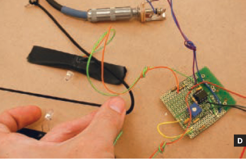
Fig. D: Test your optical pickup before installing.
Plug in the batteries, stretch an elastic band between the emitter and receiver, and test for output from the jack using a voltmeter on an AC setting or an oscilloscope. The output should jump a few tenths of a volt when you pluck the band. If you see signal, you can hear it by plugging into headphones, an amp (begin with the power turned down), or a cheap set of powered computer speakers.
If you don’t hear an amplified tone from the string, try turning up your amp, but if you go past 5, something else is probably wrong. Check that you haven’t inadvertently swapped the transmitter and receiver, which look similar, or reversed the polarity of either. Test the detector by illuminating it with a bright incandescent source, such as a 60-watt bulb or old-fashioned flashlight, instead of the IR transmitter. Direct the light into the receiver, and pluck the rubber band close to and in front of the receiver.
If you still get no signal, test the voltage between the phototransistor’s emitter and ground, across the 1kΩ resistor. If the DC voltage there is zero, chances are the phototransistor is backward. The AC voltage at this point should also increase when you pluck the rubber band. If the detector generates signal at the 1kΩ resistor but the amplifier output still doesn’t work, double-check the connections and solder joints on the board.
4. Assemble the body.
Once the circuit is working, it’s time to mount the components onto the body. First comes some drilling. Conveniently, my Coleman Camp Cooker was made of soft metal and its 2 halves come apart easily, making it easy to work with. I put holes in the case for the power switch, power indicator LED, output jack, and a standoff that holds the circuit board away from the case, to prevent short circuits (Figure E).

Fig. E: Drill holes in the case bottom for the power switch, indicator LED, output jack, and circuit board standoff.
For the photodetector, I drilled another hole centered on the body, just below the guitar’s neck. At one of the neighboring corners I drilled 2 more holes for the emitter, one for the 1" standoff and the other for the wires. Then I cut a short length of IC shipping tube to use as an arm that cantilevers the emitter over the detector (Figure F).

Fig. F: Drill the case top for the photodetector, then mount an arm to raise the emitter LED directly above it.
I drilled 2 holes in the arm, one to attach to the standoff, and the other to mount the transmitter. Take care to position the holes such that the transmitter is directly above and aimed at the receiver. All of the LED-style components — the indicator light, emitter, and receiver — press-fit easily into holes drilled with a #9 (0.196") bit.
5. Add the string, bridge, and tuning head.
I tied one end of the elastic band to the cooker’s hanging hole, opposite the handles. For the bridge, I used a piece of IC tubing with a notch in it to prevent the elastic from sliding from side to side (Figure G).

Fig. G: The bridge is notched plastic tubing.
To hold the other end of the elastic, I made a movable “tuning head” out of more tubing. I drilled 2 holes in the plastic for the cooker’s handles to pass through, and another hole higher up to tie the elastic to. This arrangement lets you easily slide the head back and forth to adjust the tension in the elastic, while the torque against the handle prevents the head from sliding on its own (Figure H).

Fig. H: The tuning head is more tubing that slides up or down the handles.
The guitar is ready to play! If you have multiple strings, the potentiometers let you even out the volumes (the signal level increases for very low notes), and otherwise protect your amp if the gain is high. The other thing to play with is the alignment of the emitter and detector. Rotating the emitter’s mounting arm may increase the signal level.
6. Play the fantastic elastic.
Due to the low tension, you can play incredibly low notes with just a short length of elastic. It also makes this instrument sensitive; depending on how you pluck or strike the strings, their tuning might change. Rather than play the elastic bass like a guitar, changing the notes by fretting against the neck, try tugging on the elastic at the neck, like with a washtub bass, or squeeze down on it behind the bridge.
You can also control the tone using your fingernail as a sliding fret, lifting the string just enough to give it a new vibrating length. Apply just slight pressure.
Notes also have a different character depending on whether you pluck them hard or soft, with the “hard” notes containing more high-frequency components. It’s easy to make a lot of cool sounds with this, but challenging to play a song. The best way I found to keep a consistent tone was to play the multiple-string instrument and gently hammer on its strings with chopsticks rather than pluck them.
Finally, remember these are optical pickups, so you can experiment with almost anything! Plucking the tines of a plastic comb held between the sensors produces a really creepy sound. Even tapping on the base of a wineglass can be amplified. For my next experimental instrument, I plan on optically amplifying the motion of glass rod.
![]() Schematics plus videos and audio recordings: makezine.com/17/diymusic_elasticbass
Schematics plus videos and audio recordings: makezine.com/17/diymusic_elasticbass
Len Keeler teaches physics and electronics at the University of Minnesota in Morris. He’s an electronics hacker devoted to the idea of DIY and making things for less.

Photography by Sam Murphy
RANDOM MUSIC BOX
Microprocessor organ and servo drum play an endless song.
Here’s a fairly inexpensive ($30–$40) project that uses a microprocessor to generate a constant stream of random but pleasant-sounding music. A Microchip PIC16F685 generates 5 square waves that are amplified and combined to play on a small speaker.
A lookup table in the software stores chord progressions common in Western music. As the music runs from chord to chord, 3 oscillators play the chord itself, 1 plays a tonic-dominant (1-5) bass pattern, and 1 plays random notes from the underlying scale as a melody. Potentiometers adjust how much of each component (chord, bass, and melody) is mixed into the final output.
To keep the beat, the microcontroller also generates output for driving a servomotor to strike a drum or equivalent.
Assemble the Circuit
Download the project schematic at makezine.com/17/diymusic_random. You can solder it onto protoboard or put it together temporarily on a solderless breadboard. I placed and connected the components in this order: sockets, resistors, capacitors, power wires, signal wires, potentiometers, and finally the off-board connections to the speaker and servo (Figure A, following page). The web page has sketches showing each step.

Program the Microcontroller
Download the project code from makezine.com/17/diymusic_random and use your PIC programmer to burn the firmware onto the microcontroller. You can either program it directly from the hex file main.HEX or compile the program from the source code main.asm.
MATERIALS
PIC16F685 microprocessor, 20-pin DIP $3 from Digi-Key, digikey.com
Op-amp (amplifier) chip, OPA4342, 14-pin DIP $5 from Digi-Key, or use another quad op-amp, like the cheaper LM324
Capacitors: 20nF, 10μF, 1μF, 100μF
Potentiometers: 50kΩ (3) or other value, but all 3 must be identical
Resistors: 4.7kΩ, 10kΩ (6)
Small speaker, 8Ω RadioShack #273-092
0.1" header, 3-contact
DIP sockets: 14-pin, 20-pin
Hookup wire
Protoboard or 2 solderless breadboards
5V power supply I used a 4xAA battery pack with a voltage regulator.
Masking tape
For the drum (optional):
Servomotor, Hitec HS-422 from a hobby shop. Other servos would probably work, but they must handle PWM (pulse width modulation) input. I tried an HS-325HB and it did nothing but twitch.
Drumstick and drum, or equivalent For one version, I used a metal rod and a cardboard box.
TOOLS
PIC programmer available from microchip.com
Digital multimeter
Soldering materials (optional) if you’re building on protoboard
Verification
Before inserting the ICs into the sockets and powering on, it’s important to make some sanity checks, to avoid destroying the expensive ICs. First, check connections on the circuit with the digital multimeter. Next, make sure the power and ground rails aren’t shorted out. Then power on the circuit and make sure each chip’s power pin (Vcc) is getting 5V. Finally, plug in the ICs. If you don’t hear music output, disconnect power immediately to avoid any magic smoke.
Add the Drum
You should now have a noisy circuit happily playing chords. To add percussion, the servo output alternates between maximum and minimum deflection every beat. The music box MAKE built uses a metal case as both project box and drum (Figure B). For my original version, I soldered the circuit onto protoboard and taped everything into a cardboard box (Figure C).


For those with some PIC coding experience, the source code for the firmware is mainly driven by lookup tables, which you can easily modify to do other musical things such as playing songs, scales, etc.
![]() For the schematic, a GIMP file with wiring, compiled firmware, source code, and an audio sample, go to makezine.com/17/diymusic_random.
For the schematic, a GIMP file with wiring, compiled firmware, source code, and an audio sample, go to makezine.com/17/diymusic_random.
Kevin Weekly studies electrical engineering and computer science at the University of Texas at Dallas. In his spare time he builds circuits, writes programs, and composes music.