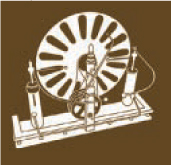
THE WIMSHURST INFLUENCE MACHINE

Photography by Jake von Slatt

SPARKS IN YOUR PARLOR
When assembling a proper laboratory, the gentleman or lady experimenter should be sure to include a Wimshurst electrostatic generating machine. This device will serve tirelessly in investigations into the field of natural philosophy, and provide interesting parlor games such as the “electric kiss.” Herein we will demonstrate the construction of such a spectacular device, with materials easily acquired from your local home center and hardware store.
Electrostatic machines create high-voltage charges without the familiar coils of copper wire, permanent magnets, and commutators found in conventional generators. They’re made of brass, glass, and wood, and they look more mechanical than electrical.
The coolest thing about them is that you can feel them working. As you begin to crank a Wimshurst machine, you can hear it crackle and hiss with energy, you can smell the sharp tang of ozone, and you can feel the hair on your arms stand up as the Leyden jars begin to charge.
Set up: p.97 Make it: p.98 Use it: p.107
Jake von Slatt is a lifelong tinkerer and maker currently residing outside Boston. He works as a Linux sysadmin for a small aerospace research firm, but his true passion is the construction of anachronistic contraptions in his Steampunk Workshop (steampunkworkshop.com).
ELECTRONS UNDER THE INFLUENCE
HOW A WIMSHURST MACHINE WORKS
In dry weather, getting up from a seat and touching a doorknob can give you a shock, because the act of separating your posterior from the chair causes a charge imbalance. The Wimshurst influence machine is essentially an idealized cycle of posteriors and chairs, endlessly sitting and standing.
How does it work? The basic operating principle is this: when you bring an electrically charged object close to an uncharged object, a charge imbalance is induced in the uncharged object. This is electrostatic induction, a redistribution of electrical charge in an object, caused by the influence of nearby charges.
In our Wimshurst machine, each metal sector has 2 sides, and there can be a charge imbalance between them. When you bring a positively charged sector near an uncharged sector, it pulls negative charges to the near side and pushes positive charges to the far side of the uncharged sector.
If you then ground the far side of the uncharged sector prior to removing it from the influence of the charged sector, you’re left with a sector that now carries a negative charge. This grounding action is the function of the neutralizing bars on our machine. The counter-rotating disks ensure that this action occurs again and again, increasing the charge with each sector interaction.
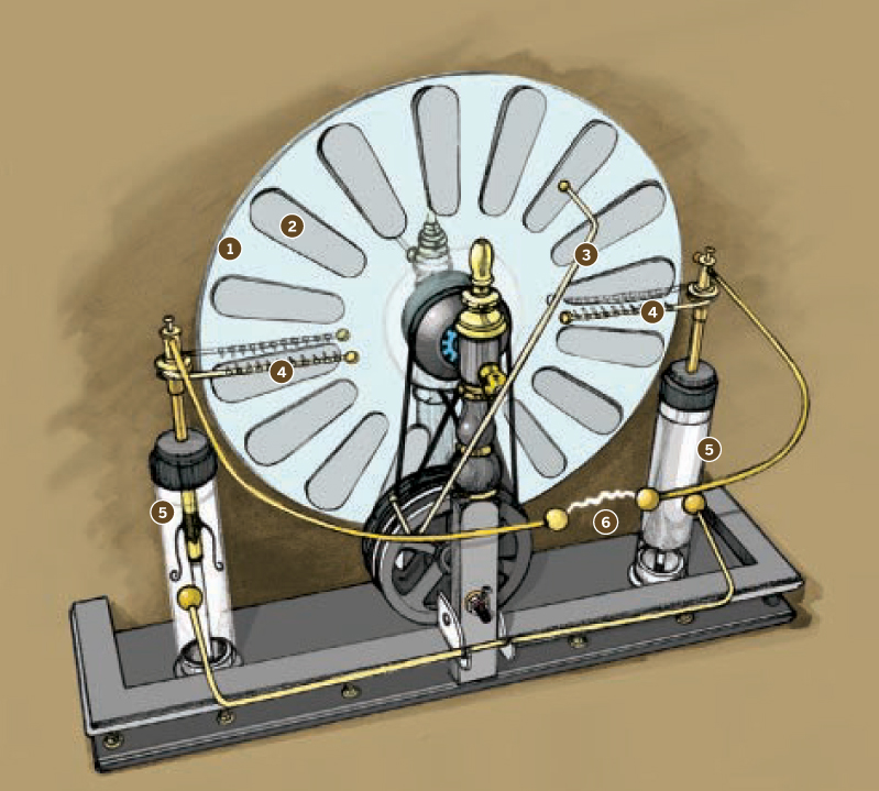
Illustration by Damien Scogin
The counter-rotating disks ➊ continually pass their metal strips (or sectors) ➋ near one another, and then separate them, increasing the sectors’ electrical potential or charge.
A pair of neutralizing bars with conductive brushes ➌ contact each sector while it’s still under electrostatic influence, grounding its positive side and leaving it with a negative charge, or vice versa.
A pair of charge-collecting combs ➍ strip off the charges — negative on one side and positive on the other — and deliver them to the Leyden jars ➎ where they are stored. (Learn more about Leyden jars on page 103.)
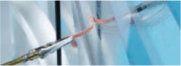
When sufficient voltage builds up, a spark jumps the gap between 2 electrodes ➏ — CRACK!
A BRIEF HISTORY OF ELECTROSTATIC GENERATORS
The earliest electrostatic generators, from the 17th century, rubbed amber, sulfur, or glass against a cloth or brush to induce a charge. Around 1865, the German physicists Wilhelm Holtz and August Toepler independently developed “influence” machines that created a charge by induction, without direct friction between electron-donor and acceptor materials.
In 1880, James Wimshurst, an English engineer and inventor, refined the design of the influence machine by using two counter-rotating disks rather than one. He never applied for patents, but he so improved the function of these machines that they became known by his name.
Wimshurst machines soon found practical application in exciting the X-ray tubes used in early medical imaging.
SET UP.
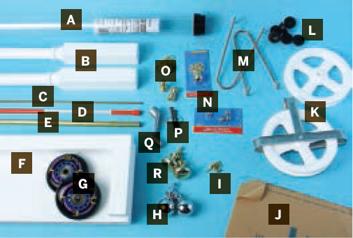
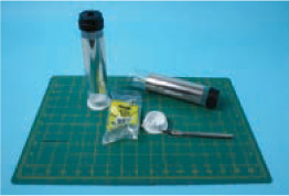
MATERIALS
The one item I couldn’t find in a home and hardware store was the pair of O-rings. The total cost of materials was about $100, but most are common items, so a little scrounging and perhaps some dumpster diving should net you significant savings.
[A] Fluorescent lamp protector sleeve for the Leyden jars
[B] Staircase balusters (2) for supports for the rotating disks
[C] 1/8" bronze brazing rod from a hardware store or welding supply shop
[D] Fiberglass driveway marker rod, 5/16" diameter
[E] 3/8" OD thin wall brass tubing, 3’ section
[F] Knick-knack shelf kit, approximately 24"×6" for the base. You can use any ¾" board, but this shelf has a nice rail that adds to the overall look.
[G] Inline skate replacement wheels (2)
[H] Large brass lamp chain pull balls (2) for the Leyden jar shunts
[I] #4 or #6×½" flathead (countersunk) wood screws (4) to mount disks to skate wheels
[J] 3/16" acrylic glazing aka plexiglass, or polycarbonate aka Lexan enough to cut two 14" circles. Polycarbonate is easier to work with but costs twice as much.
[K] Clothesline pulleys must be plastic
[L] Rubber feet (6)
[M] 1" copper pipe hangers (2) Found in the plumbing section, they’re copper-plated steel.
[N] Lamp parts Pictured here are various pull chains, brass finials, and ball nuts.
[O] Small brass ball cap nuts (2) for the electrodes. Found in the electrical section, they’re commonly used to secure the top of brass outdoor lighting fixtures.
[P] 2" drywall screws (2) with large washers
[Q] Casement window crank
[R] 3/8" threaded lamp finials (2) for the charge collectors
[NOT SHOWN]
Brass lamp finials (2) for the brush supports. These have a 3/8" threaded hole in one end and a small hole in the other. I think they’re made for ceiling fixtures that have a center pull string.
#8-32 screws (2)
Flat rubber washers (2)
3/8" OD thin wall brass tubing, 6" lengths (2)
3/8" threaded collars (2)
3/8" lamp nipples, 1" long (2)
Lamp washer nuts, threaded (2)
3/8" brass washers (2)
Brass lamp finials with ½" ball end (2) for the electrodes
¾" square dowel, 12" length or equivalent scrap. Pine works, but hardwood is preferable.
Sixpenny nails (2)
Plastic milk jug
Pushpins
5/16" bolt with large (fender) washers
Scrap of foamboard, about 15" square
Aluminum tape with peel-off paper backing found with the duct tape and HVAC supplies
Alligator clips (4) and copper braid or solder wick for the neutralizing brushes. Try RadioShack.
3’–4’ of bare copper wire
Plastic closet pole mounting sockets (2)
5/16" setscrew collars with setscrews (4) for the axles/shafts
#6-32 setscrews (2) for the neutralizing brush supports
Rubber O-ring belts (2) McMaster-Carr part #94115K259 (mcmaster.com), $15 for 8
14 AWG solid copper wire, about 12" length
Small brass wood screws (2)
TOOLS
Power drill and bits: 1/8", 5/16", countersink, and multi-step bit
Hacksaw with fine tooth blade, coping saw, and miter box
Hobby knife, scissors
Metal files: Fine metalworking, round (rat-tail), and flat crosscut intermediate (bastard)
400-grit sandpaper, #00 steel wool
#6-32 screw tap and handle
Small soldering torch and/or large soldering iron I use a Lenk LSP-180 torch. It’s a marvelous tool.
Miscellaneous screwdrivers and small pliers
Tape measure, ruler
Epoxy, cellophane tape, rosin-core solder
Drawing compass
Small carpenter’s square
MAKE IT.

BUILD YOUR ASTOUNDING WIMSHURST GENERATOR
Time: 2 Weekends Complexity: Moderate
START ≫
This is a moderately difficult project. No single operation is particularly difficult, but a variety of techniques are involved. You’ll likely find the soldering to be the most challenging, but don’t fear, it’s easier than it looks. Practice on some scraps before each operation, and you should be fine. A dimension diagram of the main parts is online at makezine.com/17/wimshurst.
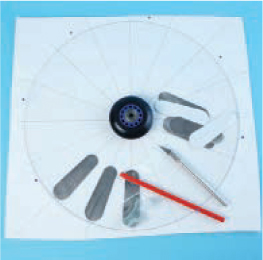
1. MAKE A CIRCLE-CUTTING TOOL
To cut the two 14" acrylic circles, we first need to make a tool.
1a. Cut a 12" length of ¾" square wood dowel. Drill a pilot hole near 1 end and press or drive a sixpenny nail through the stick so the point sticks out about ¼". Drill a second hole exactly 7" from the first and insert another sixpenny nail.
1b. Use a fine metalworking file to shape the second nail as shown. You want to make a chisel point with a slight undercut on the leading face.

2. CUT 2 ACRYLIC DISKS
2a. Lay out your circles with a compass to be sure they’ll both fit on your acrylic (or polycarbonate) sheet. Drill a 1/8" hole in the center of your circle. Be gentle when drilling acrylic, as it cracks easily. Polycarbonate is much tougher.
2b. Working on a carpeted floor, insert the unmodified nail into the center hole and begin scoring your circle with the cutting nail. Cut around the circumference, about ¼ of the way around with each stroke. If the cutter sticks, lift it out and move to a different spot. When you’ve cut about halfway through, flip the sheet over and cut from the other side. Repeat as necessary. When the circle pops free, clean up the edge with some 400-grit sandpaper, and set aside.

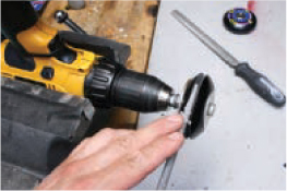
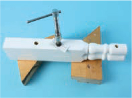
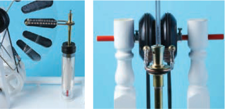
3. CUT BELT GROOVES INTO THE SKATE WHEELS
3a. Gently clamp or strap your drill to a workbench as pictured. Assemble a mandrel from a 5/16" bolt and some large (fender) washers, to grip the skate wheel. When assembled, the entire wheel must spin, not just the bearings.
3b. Chuck the assembly into the drill. The wheel should turn toward you and the speed should be fairly fast. With a crosscut bastard file, make a ¼"-wide flat on the wheel. Then switch to a rat-tail file to cut the groove. Apply light and even pressure to the file.
4. ATTACH THE SKATE WHEELS TO THE DISKS
4a. Use a step drill bit to widen the hole in the acrylic disk to 5/16". Be gentle, and go slowly, because acrylic is easily cracked.
4b. Remove the washers from the wheel and use the 5/16" bolt to center the wheel against the disk. Drill four 1/8" holes through the disk but not into the wheel. Then switch to a 3/32" bit and drill partway into the wheel in 4 places. Finish the holes with a countersink.
4c. Remove the 5/16" bolt and drill the center hole out to ½" or 5/8" using a step bit. You want the edges of the hole completely clear of the rotating parts of the wheel bearing. Install 4 small countersunk screws. Tighten these so they just touch the disk. The disk must remain as flat as possible.

5. CUT THE SECTORS
Decide how many sectors you’re willing to cut. I’m rather lazy and opted for fewer, 16 per disk. If you make 24 or 32, you’ll have to make them smaller but you’ll be rewarded with longer sparks.
Following the diagram at makezine.com/17/wimshurst, make a template from a plastic milk jug, then trace each sector onto aluminum tape. It’s a good idea to make some extra sectors to practice with. Cut them individually; don’t be tempted to stack multiple layers or your cuts will end up ragged and bleed charge away into the air.
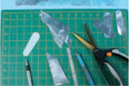
TIP: I found it easiest to use an X-Acto knife and straightedge to cut the long sides, and then switch to scissors for the curved ends.
6. ATTACH THE SECTORS
6a. Draw a 14" circle on foamboard, and draw radial lines to correspond with your number of sectors. Place your sector template centered at 6 o’clock and trace it. The large end should face out and be about ¼" from the edge of the circle.
6b. Center the acrylic disk on the foamboard and insert pushpins around the circumference so it turns in place.
6c. After practicing with some spare sectors, carefully peel and stick the first one in place. A length of fiberglass rod makes an excellent burnishing tool. Turn the disk 1 line to the left and repeat. Always index the line to the first sector you stuck down; this will help make the spacing as even as possible.
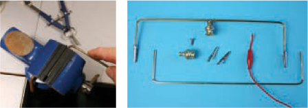
7. PREPARE THE DRIVE PULLEYS AND CRANK
7a. Remove the pulleys from their cages by drilling out the rivets, then use the step bit to enlarge the holes to 5/16". Drill from one side, then the other, to enlarge the full depth of the hole in the pulley.
7b. Cut two 7" lengths from the fiberglass rod, and slightly bevel the ends with a file to prevent chip-out. These are the disk axle and drive shaft. Be careful of the glass fibers — they can be irritating!
7c. Drill the splines out of the window crank’s bore with a regular 5/16" drill bit. Clamp the crank in a vise and drill slowly, making sure the bit is in line with the axis.
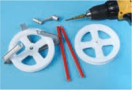
NOTE: It’s important to use the step bit here because it is self-centering.
8. CUT AND DRILL THE DISK SUPPORTS
8a. Cut a 12" length off each staircase baluster. Choose the end that you think looks best.
8b. Clamp the 2 supports together as shown and drill 5/16" holes at 3¼" and again at 11" inches from the bottom (square end).
8c. The lower hole needs to be reamed out so that the fiberglass axle turns freely in it. Use a slightly larger drill or rat-tail file. You can also drill it larger and insert plastic bushings or skate bearings for smoother operation.
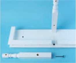
9. BUILD THE BASE
9a. Draw a line lengthwise on the knick-knack shelf, parallel to the back, 2½" in. Then draw a centerline perpendicular to the first.
9b. Cut a 1¼" gap in the rail on the centerline, as pictured.
9c. Drill two 3/8" holes in the base on the centerline, 5/8" from the front and back edges. Use 2" drywall screws and large washers to attach the disk supports to the base. The oversized holes and washers will allow you to adjust and align the position of the rotating disks precisely.
9d. Drill two 5/16" holes on the lengthwise line, 75/8" from the centerline on each side. These need to be perfectly vertical, so use a small carpenter’s square to line up the drill.
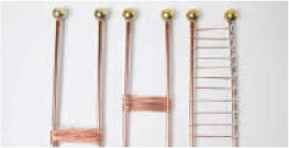
10. MAKE THE CHARGE COLLECTOR COMBS
10a. Cut each pipe hanger to 5" with a hacksaw, removing the nail ends. Save the scraps. Place the small brass ball nuts on the ends, heat them with a small torch, and apply just enough solder to fill the joint.

NOTE: The pipe hanger is copper-plated steel; be careful not to overheat it or the solder may not adhere.
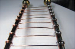
10b. You need to make 8 to 12 pointy prongs down each side of the collector combs. Wrap copper wire around each pipe hanger (I made 11 turns), then cut away the center portion on 1 side only and bend the cut ends around the pipe hangers. Spread these wires out evenly along the portion of the charge collector that will face the sector.
10c. Solder the prong wires. Crimp the ends tightly around the pipe hanger and use a large soldering iron to solder each joint. Apply sufficient solder so that it flows down to fill the gap at the end of each length of wire. We want to avoid any points other than the prongs themselves.
Once you’ve soldered all the joints, cut down the center of the wires, but don’t trim the prongs to length until it’s time to install the combs.
11. PREPARE THE CHARGE COLLECTOR MOUNTS
11a. Using the step bit, bore out half of the threaded collar. Screw the nipple halfway into the collar. Insert the brass tubing into the other end and solder it in place.
11b. Drill a hole straight down into the top of the 3/8" threaded finial and thread it with a #6-32 tap. Use the drill size written on the tap. Then drill a 1/8" hole through the body of the finial as shown; this is for the discharge electrode.

11c. Cut a ½" length from the scraps you trimmed off the pipe hanger, and solder it to the brass washer. This will allow the assembly to clamp and hold the charge collector perpendicular to the support. Test-assemble the mount, and then disassemble and set it aside. Make another the same way.
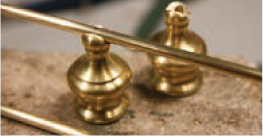
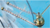
12. MAKE THE DISCHARGE ELECTRODES
12a. Cut two 15" lengths of brazing rod and bend them as shown. I bent mine by hand but you could bend a 30" length around a 5gal pail and then cut it in the center for a neater appearance.

12b. With a hacksaw, cut ½" balls off 2 brass lamp finials. Solder 1 ball to each electrode; fill the hole with solder so it makes a smooth transition to the rod.

NOTE: Do not solder the small ball nuts in place! You’ll use them after you attach the electrodes to the charge collector mount.
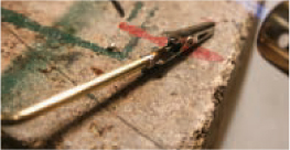
13. FABRICATE 2 NEUTRALIZING BRUSH SUPPORTS
13a. Cut two 14" lengths of brazing rod and make two 90° bends in each as shown, 2" from either end. These are the brush supports.
13b. Solder the brush supports to the brush bosses (hubs). First drill a sideways hole for a setscrew in the base of the finial, and tap it with the #6-32 tap. File a groove in the top of the finial, then center the brush support bar on the finial, prop it parallel to the workbench top, and solder it in place.
13c. Crimp the alligator clips onto the ends of the brush support bars, and solder.
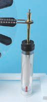
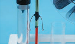
14. FABRICATE THE LEYDEN JARS AND SHUNT
14a. Make the Leyden jar shunt. Cut a 22" length of brazing rod and make a 90° bend 3½" in from each end. Solder 2 large brass lamp chain pull balls to the ends. (Smaller finial balls or cabinet knobs would work, too. If you use knobs, be sure to remove any lacquer finish.)
14b. Cut the Leyden jar bodies. Using the miter box and fine tooth hacksaw, cut two 7½" lengths from the fluorescent lamp protector sleeve.

Leyden Jars
The Leyden jar is the granddaddy of the modern capacitor. It consists of inner and outer layers of metal foil separated by a dielectric, or insulator. The amount of charge the jar can hold is determined by the area of these 2 plates, their distance from each other, and the insulating capability of the material between. Original Leyden jars were made with silver or lead foil and glass. However, plastic is a far superior insulator due to glass’ propensity to absorb water molecules, thus reducing its dielectric properties.
Our Leyden jars are large enough to give you a jolt, but not so large as to harm a healthy person. Leyden jars capable of administering a lethal shock are quite easily built — so be sure you fully understand their properties if you decide to construct larger jars than those here.
The first generally acknowledged accidental death by electrocution occurred in St. Petersburg, Russia, in 1783 when a professor brought his head a bit too close to a charged bank of Leyden jars.
14c. Affix the inner and outer plates. Cut four 5"×6" sheets of heavy-duty aluminum foil. Form 2 sheets by wrapping them around the tubes along their 6" axis, so each foil cylinder is 5" high. Insert 1 cylinder into each tube so that it’s 1" from 1 end, then use a couple of rolled-up sheets of paper to hold the foil firmly against the inside of the tube while you tape it in place, the tighter the better.
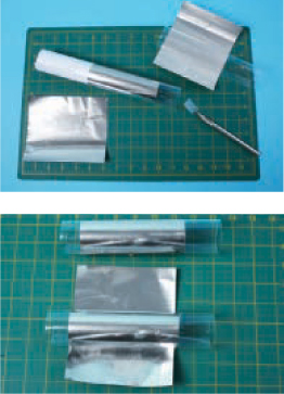
Wrap 1 piece of foil around the outside of each tube, and tape it in place. Again, the tighter the better, but don’t wrinkle the foil.
14d. Snap the tube end caps onto the opening that is 1" from the foil. Make the Leyden jar bases from a pair of plastic closet pole mounts; I had to trim off some reinforcing ribs with an X-Acto knife to make them slide into the tubes. Drill out the center hole to 5/16".
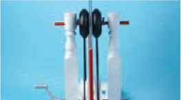
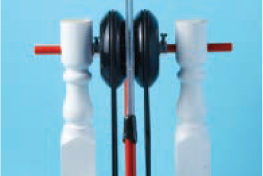
15. MOUNT THE DISKS AND DRIVE LINE
15a. Slide the disk axle through the top holes in the supports, adding a 5/16" setscrew collar, an O-ring belt, the 2 disks, the other belt, and another collar, as shown.
15b. Attach the casement window crank to the drive shaft. Insert the bushings in the supports if you’re using them, slide the shaft through the pulleys, and put a setscrew collar on either end. The pulleys should be tight; you’ll have to twist the shaft back and forth to get it through.
15c. Stretch the belts around the pulleys; don’t forget to twist one, so that the disks rotate in opposite directions. (In this photo, the belt with the twist is hidden behind the disk. What you are seeing is a reflection of the untwisted belt.)
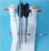
NOTE: You might need a spacer between the disks. My machine became difficult to turn once it was fully charged, due to the electrostatic attraction of the disks. I cut a 2½" washer from a plastic milk jug and placed it on the shaft between the disks to remedy this problem.
16. ALIGN THE DISK AND COLLECTOR SUPPORTS
Cut two 11" lengths of fiberglass rod and press them into the holes in the base. Loosen the screws that hold the 2 disk supports and adjust them so the disks are perfectly in line with these charge-collector supports. Retighten the supports.
17. INSTALL LEYDEN JARS AND CHARGE COLLECTORS
17a. Slide the Leyden jar bases, then the charge collector assemblies, over the fiberglass charge collector supports.
17b. Use about 6" of 14 AWG solid copper wire to form each inner plate contact. Wrap it once around the brass tube and form 2 loops in the ends.
Using a scrap of the plastic tube as a guide, adjust the inner plate contacts so they apply even, gentle pressure. You want good contact with the foil but you don’t want to rip it when you install the Leyden jars.
17c. Apply epoxy to the end of the fiberglass support rod, slide the brass charge collector assembly down onto it, and set it aside while the epoxy cures.
17d. Slide the Leyden jars onto their bases, being careful not to tear the foil as you make contact.
17e. Line up the charge collector combs, test-spin the disks to see if there’s any wobble, then trim the prongs to come as close as possible to the disks without touching. Tighten the charge collector assemblies to hold the combs in place.
18. INSTALL DISCHARGE ELECTRODES AND NEUTRALIZING BRUSHES
18a. Insert the discharge electrode into the finial on the charge collector and tighten the screw to hold it in place. (The finial should be tight enough to hold the collector comb but still allow the electrode to move. If it’s too tight, or not tight enough, the support rod can be twisted in the base to accommodate.)
18b. Wrap a bit of tape around the bare end of the electrode and screw on one of the small ball nuts; this will prevent charge from bleeding off the sharp end. Repeat with the second electrode.
18c. Slide the neutralizing bars onto the upper shaft and align them roughly 45° from the collector combs. A sector should pass through a charge collector, encounter a neutralizing bar after about 1/6 of a rotation, and then encounter the other charge collector after a further 1/3 of a rotation. Tighten the setscrew to secure.

18d. Add the neutralizing brushes. Clip 1½" lengths of solder wick or copper braid to the ends of the neutralizing rods so they make good contact with the disk.
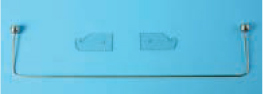
19. MOUNT THE LEYDEN JAR SHUNT AND ADD FINISHING TOUCHES
19a. Cut the 2 acrylic brackets as shown in the parts diagram, then use small brass wood screws to attach them to the front disk support, leaving them a little loose at first. Place the Leyden jar shunt in the brackets and line them up so the balls on the shunt lean comfortably against the Leyden jars. Tighten the brackets.
19b. Attach the 6 rubber feet to the base.
19c. The tops of the 2 disk supports looked a little bare to me, so I raided my junk box for more lamp parts and came up with these decorative finials. The wealth of finial and cabinet knobs at the typical home center means that there are infinite opportunities for creativity here! That’s it. Your Wimshurst machine is done!

![]() CAUTION: HIGH VOLTAGE! This machine, or more specifically the Leyden jars that are a part of it, are capable of delivering shocks in excess of 50,000 volts. While the current is quite low and therefore unlikely to harm a healthy person, a serious jolt might knock you off your feet — and who knows what your head will hit on the way down. Please be careful and treat all sources of high voltage electricity with the utmost respect.
CAUTION: HIGH VOLTAGE! This machine, or more specifically the Leyden jars that are a part of it, are capable of delivering shocks in excess of 50,000 volts. While the current is quite low and therefore unlikely to harm a healthy person, a serious jolt might knock you off your feet — and who knows what your head will hit on the way down. Please be careful and treat all sources of high voltage electricity with the utmost respect.
FINISH X
NOW GO USE IT »
USE IT.
LET THE SPARKS FLY
OPERATION
There are 3 variables you can play with: size of the spark gap, angle of the neutralizing bars, and switching of the Leyden jars in and out of circuit.
Start with the spark gap set to about 1", the neutralizers at 45° to the collector combs (90° to each other), and the Leyden jars disconnected. Turn the crank smoothly at a moderate speed. The electrodes should produce a thin blue spark. Look closely and you’ll notice that one end is brighter; this is your positive electrode.
Stop cranking and engage the Leyden jars. These can hold a charge for days. From this point on, consider the machine “hot” until you short the electrodes by simultaneously touching both with the tip of a screwdriver. Also be warned that Leyden jars can acquire charge just sitting there, so you need to discharge them this way each and every time before you touch the electrodes.
Turn the crank again. After several revolutions you’ll hear the neutralizing brushes crackle, you’ll smell the fresh scent of ozone, and — CRACK! — a strong blue spark will jump the gap.
ADJUSTMENTS
Short the electrodes and reposition them a little farther apart. Crank some more and you’ll see a bigger spark. Repeat this procedure until you see multiple small sparks jump from one of the collectors, across several sectors, to a neutralizing brush. You’ve reached your maximum spark length.
After you find the maximum gap, you can adjust the neutralizing bars. Narrowing their angle from 90° to about 60° will increase the maximum voltage at the expense of a small decrease in current.
MAINTENANCE
Your machine should require little maintenance, but may require periodic replacement of the belts and cleaning of the disks. Use only water to clean them, or rubbing alcohol if you suspect there is oil on them.
THE ELECTRIC KISS (AND OTHER ENTERTAINMENTS)
Wimshurst machines had a place in Victorian entertainment. After a fine meal, guests might adjourn to the parlor for games, discussion, and scientific demonstrations. One can imagine the visceral impact of the Wimshurst machine, with its spinning glass disks, electrical discharges, and the loud report of 6" sparks.
For the adventurous, in the right company, there was a demonstration known as the electric kiss. Two volunteers would stand on insulating surfaces. Each would touch one of the 2 charge collectors and then they’d slowly, without any other part of their bodies touching, bring their lips together for the inevitable “tingle” of electricity.
CAUTION: Demonstrate the electric kiss only with the Leyden jars taken out of the circuit, to avoid a painful jolt.
![]() To demonstrate the Wimshurst machine with Franklin’s Bells, see makezine.com/17/wimshurst.
To demonstrate the Wimshurst machine with Franklin’s Bells, see makezine.com/17/wimshurst.
For further reading, I suggest:
Ford, R.A., Homemade Lightning: Creative Experiments in Electricity, 2001
Francis, G.W., Electrostatic Experiments: An Encyclopedia of Early Electrostatic Experiments, Demonstrations, Devices, and Apparatus, 2005
![]() See the Wimshurst machine in action at makezine.com/17/wimshurst and on Make: television, Episode 103, at makezine.tv/episodes.
See the Wimshurst machine in action at makezine.com/17/wimshurst and on Make: television, Episode 103, at makezine.tv/episodes.