
Photography by Ed Troxell
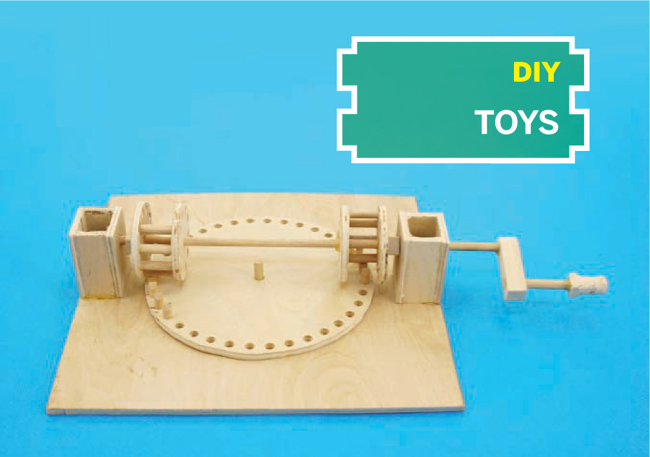
DA VINCI RECIPROCATING MECHANISM
 Re-create Renaissance tech to convert rotation into a square wave.
Last year I was blown away by the clever mechanisms displayed in the Leonardo da Vinci exhibit at the Tech Museum of Innovation (thetech.org) in San Jose. I was especially taken by da Vinci’s simple mechanism for powering a sawmill with a water wheel. I made my own tabletop model of the mechanism, and it never fails to gather a crowd when I show it off.
The typical mechanism for converting between rotation and reciprocal motion is a flywheel and a crankshaft, like on a steam locomotive. But da Vinci’s simple device starts with 2 modified cage gears (aka lantern gears) that rotate on a common shaft. Each cage has half of its teeth missing, on opposite sides of the shaft from the other gear, so that when turned, they alternately engage with the pegs on opposite sides of a large wheel.
When you turn the shaft at a constant rate, this mechanism generates square-wave motion, rather than the sinusoidal motion of a piston. This is because each cage gear turns the wheel at a constant speed, and it lets go right before the other one comes pushing full-speed to turn the wheel the other direction.
Cut the Pieces
I built my initial prototype by hand, and it took a lot of trial and error to get the peg spacing right. So I made a more precise second version by laying out the plywood pieces in Google SketchUp (sketchup.google.com), then importing them into CorelDraw and using the Corel files to cut them on an Epilog laser cutter.
MATERIALS
¼″ birch plywood, 12″×18″
¼″ wood dowel, 36″ long
½″×½″ square wood molding, at least 4″ long aka square dowel
Wood glue
TOOLS
Band saw or jigsaw
Drill press with circle cutter and ¼″, ![]() ″, and
″, and ![]() ″ bits
″ bits
Laser cutter (optional) instead of the band/jig saw and drill press
Small saw for cutting dowels
File, sanding block with medium-grit sandpaper, or Dremel with sanding bit
Glue gun with hot glue
C-clamps (2)
Spray adhesive and computer with printer for the paper templates, if you don’t use a laser cutter
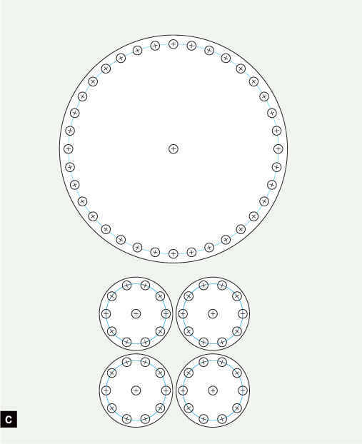
The main plywood pieces you need to cut are 4 identical discs for the cage gears and a larger disc for the wheel (Figure A). Each cage gear disc is 2.06″ in diameter, with 10 equidistant ¼″ holes spaced 0.84″ away from its center point. The wheel is 6.4″ wide with 36 equidistant ¼″ holes spaced 2.95″ from its center.

Fig. A: The main plywood pieces for the base, large gear, 2 cage gears (aka lantern gears), and one of the 2 towers.
To match da Vinci’s plan, I also cut 8 interlocking rectangular pieces that assemble into the 2 towers that hold the crankshaft. You can download my SketchUp and Corel files at makezine.com/24/davinci, along with full-size PDF templates that you can use to make the pieces by hand (Figure C).
Diagrams by Alan Federman
Fig. C: Gear layout drawing. Drill the holes before you cut out the gears; you really only need 10 holes in the large wheel, and 4 in each cage gear disc.
If you’re cutting by hand, print out the 3 full-size templates, cut the shapes out of the paper, and temporarily affix them to the plywood with spray adhesive. Drill all the holes before you cut the discs out of the plywood, ![]() ″ holes in the center and ¼″ holes around the perimeter. Functionally, the mechanism needs only 26 holes cut, 4 in each cage gear disc and 10 in the large wheel. But I cut holes all the way around the perimeters of all the discs, 76 total, so that I could use the parts for other purposes, such as a crank assembly for a crane.
″ holes in the center and ¼″ holes around the perimeter. Functionally, the mechanism needs only 26 holes cut, 4 in each cage gear disc and 10 in the large wheel. But I cut holes all the way around the perimeters of all the discs, 76 total, so that I could use the parts for other purposes, such as a crank assembly for a crane.
In addition to the discs, you need plywood pieces for the base and the towers. The base is simply a 10″ square with a ![]() ″ hole in the center to hold a vertical axle peg for the wheel.
″ hole in the center to hold a vertical axle peg for the wheel.
The 2 towers sit on either side of the wheel and hold the drive shaft above it horizontally. I used the laser cutter to fashion them out of interlocking pieces of ¼″ plywood, and you can also make them by cutting and gluing simple plywood rectangles; the PDF templates include plans for both. You can also cut the towers out of solid blocks. But don’t drill the tower holes yet; you’ll do this later, to ensure they’re at the correct height.
From the ¼″ dowel, you need to cut one 12″ length for the drive shaft, one 2″ length for the hand crank, eight 1¼″ pegs for the cage gears, one 1″ peg for the wheel’s axle, and ten ⅝″ pegs for the wheel’s gearing (Figure B). If you mark the pegs for cutting all at once, include some extra length for the width of the saw blade, or else the pegs might wind up too short.
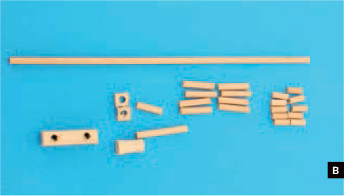
Fig. B: Dowels, wooden washers, and crank assembly parts. The same dowel is used to make the crankshaft and gear pegs.
From the ½″ square dowel, cut and drill 2 thin slices to make washers that will fit over the drive shaft. Also cut a 2″ block, and drill 2 parallel ![]() ″ holes through the block at opposite ends. Then cut another short piece, file it to make a round knob, and drill a blind
″ holes through the block at opposite ends. Then cut another short piece, file it to make a round knob, and drill a blind ![]() ″ hole halfway into the knob.
″ hole halfway into the knob.
Assemble and Adjust
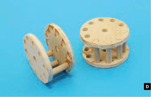
Build the 2 lantern gears by gluing four 1¼″ pegs, positioned contiguously, between each pair of the smaller discs. Use wood glue and make sure the discs are aligned parallel (Figure D).
For the wheel axle, glue a 1″ peg into the hole in the center of the base. Don’t glue the towers together yet.
Sand or file one end of each ⅝″ peg so that it’s slightly rounded and tapered on 2 opposite edges; this helps the pegs engage with the cage gears (Figure E). Glue the pegs into the wheel, 5 in a row on opposite sides, with 13 empty holes (or undrilled hole positions) between them in each direction (Figure F). The pegs should sit flush with the under-side of the wheel, stick up ⅜″ from the top face, and be oriented with their tapered edges facing the neighboring pegs. Let everything dry overnight. Get some sleep; tomorrow we have fun.
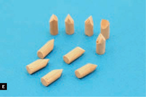
Fig. E: It’s helpful to taper the pegs for the large gear; this wil help them to mesh smoothly with the cage gears.

Fitting the gears together is a bit tricky and takes some patience. First, fit the wheel over the axle. Then mesh a lantern gear with the wheel’s pegs on one side and use it to find the correct height for the crankshaft. This is the hardest part, but it’s critical to smooth operation.
The best way is to drill 2 of the wide tower pieces a little above where you think the crankshaft should go. You can mark the point by running a ballpoint pen filler through the cage gear (Figure G). Use a ![]() ″ bit so that the crankshaft spins freely.
″ bit so that the crankshaft spins freely.

Fig. G: To measure the proper height for drilling the mounting towers, mesh a cage gear with the large gear’s pegs, and mark where the shaft will meet the tower. Then drill slightly above your mark.
Then repeatedly clamp the 2 tower pieces down, test the drive shaft through them, and sand down the tower’s bottoms evenly until you reach a good height. (As an alternative, you could make the tower heights adjustable with a tongue-and-groove and a small setscrew, but this cheats the nice all-wood feel of the project.)
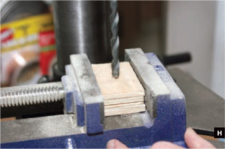
Once you have the proper height, stack the other tower pieces and cut and drill them to match (Figure H). Glue the tower pieces together.
For final adjusting, hot-glue the towers to the base (Figure I). Assemble the crankshaft through the towers, hot-gluing the cage gears in place. Work the mechanism in both directions and watch closely to see where any pegs stick, then sand down the pegs and cage gear dowels as needed (Figure J).
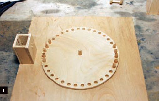
Fig. I: Mounting the first tower. If it’s a bit too high, you can sand down the bottom. If it’s too low, you can shim it up.

Fig. J: Adjusting the height of the peg teeth and rounding them slightly with a file is an alternative way to fine-tune the operation.
When everything works smoothly, mark the precise locations of the cage gears on the crankshaft, the towers on the base, and the shaft where it exits the towers; you’ll glue the wooden washers here to prevent the shaft from sliding back and forth. You can put the washers inboard or outboard of the towers; outboard makes it easier to test-glue and adjust the washers.
Using wood glue, permanently reglue the towers to the base (rethreading the crankshaft if necessary to add your washers), and reglue the cage gears in place. Hot-glue the washers in place, test the mechanism again, then reglue them permanently.
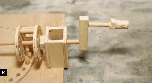
Finally, glue the crank pieces onto the longer protruding end of the crankshaft, and crank away (Figure K).
![]() Download the Sketchup and Corel files as well as a full-size template from: makezine.com/24/davinci
Download the Sketchup and Corel files as well as a full-size template from: makezine.com/24/davinci
Alan Federman lives in San Jose, Calif., and is an instructor at the TechShop in Menlo Park (techshop.ws).
Picture Frame Messages

Save PowerPoint slides as JPEGs and you can load any phrase you want into a digital picture frame. First measure the height and width of your frame’s screen, double them, and enter the doubled dimensions in Page Setup — this gives a higher-resolution image. Then type your slides, export them by selecting Save As → *.jpg, and copy the JPEGs to your picture frame. You can even upload my alignment slide at makezine.com/24/tips to find the true edges of your frame, and then adjust your slides to fit your frame perfectly.
—Herschel Knapp
Find more tools-n-tips at makezine.com/tnt.