Homemade Home Security
Build a 4-camera surveillance system and watch from any web browser.
My basement office/workshop is a fair distance from the front of the house, and I frequently want to check the front porch for mail, UPS deliveries, and the arrival of friends. I have experimented with various ways of monitoring the activity there and have found none as useful as a real-time video feed.
Getting video from a camera on the front porch to a screen in the basement is a trivial undertaking, but as projects like this are apt to do, it grew into a $200 four-camera, full-color system that can be monitored in my workshop or from any web browser. Some commercial systems can do the same thing, but they cost much more or use only black-and-white cameras. Meanwhile, I learned that switching composite video signal is actually very easy, doable with a 35¢ CD4066 analog switch chip.
START
1. INSTALL THE CAMERAS
First, of course, you’ll want to decide where the cameras go. I have one mounted on my front porch, aimed at the front door and mailbox; a second camera looking down on the driveway, so I can see when someone arrives by car; a third looking over the pond, garden, and garden railroad; and a fourth giving a view of the front yard. You’re welcome to see the live camera feeds at n3enm.hopto.org:888 and operate the system controls at n3enm.dyndns.org:8888.
The Harbor Freight security cameras screw-mount to any beam and have a 6’ cord that terminates in a 6-conductor RJ11 (technically, RJ25) telephone jack. The jack accepts an included 80’ extension cable, the other end of which splits into a yellow RCA plug for composite video, a white RCA plug for audio from the camera’s microphone, and a barrel connector for 9V DC from the included wall wart power adapter.
I haven’t set up the software to put the cameras’ audio online, but I did connect the audio from the front door camera to an old pair of computer speakers in my basement office. This lets me hear the sound of the newspaper hitting the driveway when I’m working in my office early in the morning.
The cameras and cables have proven to be weatherproof when protected from direct rainfall under a roof (Figure A), but the RJ11 connector between the camera cable and the extension cable became corroded from moisture. I sealed the connector inside a plastic bag and have had no problems since.


Check the cars in the driveway to see who’s home, or make sure all’s well around the house when you’re on vacation.
L-Dopa; David Bodnar (A); Gregory Hayes (B)
MATERIALS
Security cameras, weatherproof, color, with night vision and 80’ cable Harbor Freight item #95914 (harborfreight.com), about $40 each, or other security camera with composite video output
Composite video to USB adapter I started with an expensive (over $100) Pinnacle device, but later tried the EasyCap, an unbranded dongle available for about $7, which has worked flawlessly for over a year.
Computer, Windows-based, with a USB 2.0 port
Web streaming software like Yawcam (yawcam.com). This free software has some features that I don’t use but may be handy for others, like the ability to send an email when a camera detects activity.
For video switcher; most electronic components available at Jameco (jameco.com):
Video switcher PCB available at trainelectronics.com for $12, or download the ExpressPCB files to make your own at makeprojects.com/v/30. You can also just use a plain breadboard and hookup wire.
Microcontroller, Picaxe-14M or PIC16F684
Quad analog switch chip, CD4066
Voltage regulator, 5V, LM7805
LEDs, 3mm or 5mm, different colors (4)
Resistors, ¼W: 470Ω (4), 10kΩ (4)
Toggle switches, SPST (4) or you can use a 4-position DIP switch
Potentiometer, linear, 10kΩ–100kΩ I used a 50kΩ pot.
Capacitor tantalum, 10μF
DIP sockets, 14-pin (2)
Power supply, 9V–12V DC, 2A
RCA jacks, panel-mount (4)
RCA cable
DC power jack, panel mount to match power supply; size M and size N coaxial are common
Wire, 18–20 gauge, stranded, insulated, various colors
Project box, 6"×3"×2" RadioShack #270-1805 (radioshack.com) or similar
Machine screws, #4-40×1", with matching nuts (4) for mounting PCB
Plastic standoffs, ¾" (4) Buy them or cut lengths from plastic tubing or a pen barrel.
For Picaxe microcontroller:
Resistors, ¼W: 10kΩ (1), 22kΩ (1)
Pin header, straight, male, 3-pin for programming
For PIC microcontroller:
Pin header, straight, male, 4-pin for programming
TOOLS
Soldering iron and solder
Wire cutters and strippers
Screwdriver
Drill and drill bits widths to match LEDs, RCA jacks, switches, and mounting screws
For Picaxe microcontroller:
USB programmer for Picaxe SparkFun #PGM-09260 (sparkfun.com)
3-conductor wire connected to 3×1 female pin header
For PIC microcontroller:
PICkit 3 in-circuit programmer Microchip #PG164130 (microchip.com)
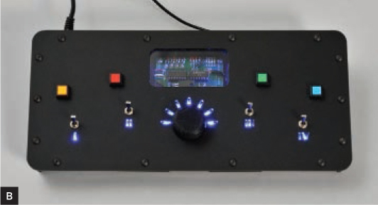
The camera video cables will plug into a homemade video switcher (Figure B, page 45), which connects to a PC via the composite video-to-USB adapter. Using the camera cable wiring (Figure C), you can easily shorten the cables for cameras installed closer to the switcher. You can also lengthen a cable, but the video quality may suffer.
2. BUILD THE VIDEO SWITCHER
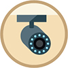
A video switcher takes inputs from multiple cameras and cycles through them at a user-settable interval (between 1 to about 30 seconds), routing each of them in turn to its single video out. It’s not a complex device, and it contains just 2 chips: a 4066 quad analog switch and a Picaxe-14M or a PIC16F684 microcontroller (either one works). The 4066 routes the video inputs to the single output. Meanwhile, the microcontroller controls which cameras are active, reading from 4 toggle switches, and times the interval that each camera is given, reading the setting from a potentiometer. Four LEDs provide additional visual indication of which cameras are on.
Figure D shows the schematic for the Picaxe-14M switcher; you can see it full-sized, along with the PIC16F684 version, at makeprojects.com/v/30. The 4 camera inputs run to switcher input pins 1, 11, 8, and 4, and microcontroller output pins 2–5 (IC pins 8–11) determine which one routes to the shared video out. On the input side of the controller, input pins 0–5 (IC pins 3–7) read from the toggles and potentiometer.

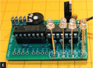
To build the switcher, first solder the onboard components as marked on the PCB, with 14-pin sockets in place for the switcher and microcontroller chips. I connected the LEDs sticking up on their untrimmed leads, to poke through the enclosure with the board mounted upside down, but you can also connect them offboard with wire, as MAKE Labs did in Figure B. You can use a small onboard potentiometer as shown here (Figure E), or a longer one for making adjustments without opening the enclosure.
For the offboard connections, solder the center leads from the RCA jacks, which will carry the camera signals, to pads In1–In4 on the board. Solder one side of the toggles or DIP switches to Sw1–Sw4 on the board. For ground, run wires connecting the outer contacts of the RCA jacks and the unconnected legs of the switches (Figure F). Don’t connect the DC power jack or video out cable yet.

David Bodnar
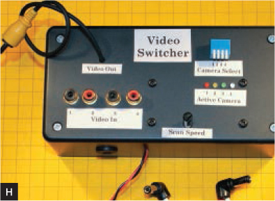
Drill holes in the project box for the PCB mounting screws, LEDs, switches, RCA jacks, power jack, and video out cable, marking positions for proper PCB alignment. Cut the RCA cable, thread the cut end through a hole drilled in the enclosure, tie a knot for strain relief, and solder it to Video Out on the board, center contact to (+) and outer shield wire to (–). Mount everything. I mounted the PCB and controls inside the lid (Figure G, following page). If you’re using DIP switches, which aren’t designed for panel mounting, you can thread the wires through small holes and glue the switches to the outside. The completed unit is shown in Figure H with labels.

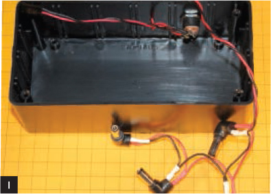
Rather than use 4 wall warts for camera power plus another for the circuit, I supply them all with a larger supply rated at 2A at 12V DC. To do this, cut the plugs off the included adapters and wire them in parallel to the DC power jack. Then wire another parallel pair of leads from the the DC power jack to (+) and (–) in one corner of the board. The power plugs can plug into the camera cables inside or outside the box (Figure I).
3. PROGRAM, CONNECT, AND CONFIGURE
Download the project software for the Picaxe or PIC microcontroller at makeprojects.com/v/30, and follow the directions there if you haven’t programmed the microcontroller before. The 2 versions of the software are almost identical. The main differences are in how variables and pins are named.
With the PIC16F684, which you program via 4-pin ICSP (in-circuit serial programming), you must configure your programmer so that pin 4 (MCLR) is set to an input pin, and you must have the switch connected to that pin (UseCamera2) set to Off. Compile and upload the code to the microcontroller, plug the chips into the PCB, and you’re ready to connect.
Make sure the EasyCap unit is switched to NTSC video, not PAL. Plug it into the computer’s USB port, install the driver from the included CD when prompted, and continue past any warning that the driver hasn’t passed Windows Logo Testing.
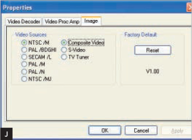
Download and install Yawcam (yawcam. com), then launch it and select Settings → Detect WebCam. Syntek STK1150 should appear in the list of devices. Select Settings → Device (Syntek STK1150) → Device Properties and specify NTSC/M and Composite Video (Figure J).
From the main menu, select Settings → Edit Settings, then choose Startup and Start Stream Output. Click on Stream → the default port number should be 8081. I changed this to 8888 to accommodate other devices on my network, but you can leave it at 8081.
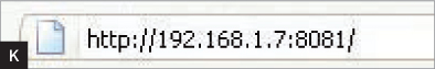
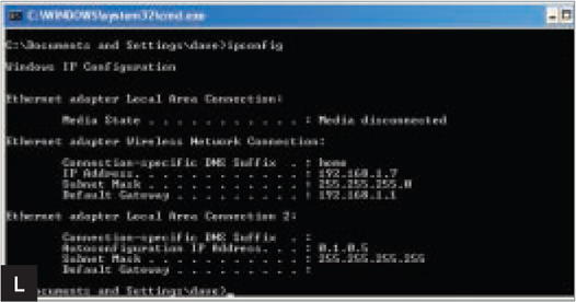
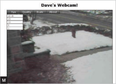
Select File → Enable Stream-output. If your computer’s firewall warns you that it’s blocking a port, select Unblock. To see the webcam image, enter your local IPv4 address followed by “:8081” into a web browser (Figure K). You can determine this address by entering ipconfig in the Windows command window (cmd.exe) and looking for the IP Address value (Figure L). You should see the Yawcam server screen with your live webcam image (Figure M)!
ROUTER CONFIGURATION
If you’re only going to view the streaming video from Yawcam from within your home network, you’re done. But to access it remotely via the web, you must configure your router or firewall to permit the Yawcam computer to be seen. This usually involves setting Port Forwarding so that the computer’s IP address can be accessed from outside the firewall. See portforward.com for detailed information on how to do this with a great number of different routers, likely including yours.
If your router dynamically assigns IP addresses (most do) you will also need to assign a static IP address for the computer running Yawcam. See portforward.com/networking/static-xp.htm for instructions.
Most ISPs will change your local IP address from time to time, which stops any URL derived from it from working. To create a URL that always works, I use the No-IP Free Dynamic DNS (noip.com). To use this free service, you install a small program on your home PC that automatically checks the local IP address and redirects a web address you specify to this address. This is why the URL for my system is n3enm.hopto.org:8888. I chose the prefix “n3enm,” my ham radio call, at one of the No-IP’s domains, hopto.org.
CONCLUSION
I’ve had this system working for almost 2 years, and I rely on it throughout the day. It’s really convenient to pull it up on my phone and check the cars in the driveway to see who’s home, or to make sure all is well around the house when we’re on vacation. Others use it, too; friends of mine who travel south for the winter check it to see how much snow is piling up back in Pittsburgh!
Meanwhile, I have experimented with X10 controllable pan-and-tilt mechanisms for the cameras, which may become permanent additions to the system. I also used EzCom2Web (easyvitools.com/ezcom2web) to add a web-based control page that lets you pan, tilt, and switch the cameras.
I hope you find this system just as useful as I have. Give it a try and let me know if I can help ([email protected]). ![]()
![]() See makeprojects.com/v/30 for code, schematics, and programming instructions.
See makeprojects.com/v/30 for code, schematics, and programming instructions.
David Bodnar is an avid electronics tinkerer, woodworker, programmer, model railroader, and cyclist whose electronic projects tend to support one or more of his other hobbies. Since he first began experimenting with BASIC Stamps over 15 years ago he has designed and built scores of Picaxe and PIC-based gizmos and gadgets, many of which are documented on his trainelectronics.com site.