

Steve Hoefer
The Eternal Flame
Build simple, nearly indestructible LED lanterns.
IF YOU’RE LIKE ME, YOU’RE THE BANE OF hardware store employees. I wander through the whole place picking up everything, looking at possibilities more than parts. Can they help me find anything? “No thanks,” I answer. What am I working on? “I don’t know yet,” I say. They move on, keeping a suspicious eye on me.
Some things just seem useful, even if I can’t think of how at the moment. One time I found matched pairs of PVC caps and plugs that fit together into little airtight pods of various sizes. For what, I didn’t know — until I wanted a way to float lit LEDs down a stream.
The result: simple, rugged, floating LED lanterns that glow for days. They’ve survived being submerged for a week, frozen, and laundered in the washing machine. I even hit one with the lawn mower, and it still works. When they get dirty, just hose them off.
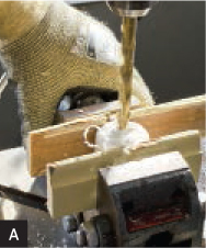
1. Drill the hole for the LED.
Drill a hole in the top center of the cap using a ⅜" bit; it’s just under 10mm and will make a watertight fit for the LED.
Use a drill vise to prevent kickback. To protect the cap from scratches, you can line the vise jaws with tape or cut a V in 2 pieces of scrap wood (Figure A).
![]() TIP: You can remove unsightly factory markings from PVC with a rag soaked with acetone.
TIP: You can remove unsightly factory markings from PVC with a rag soaked with acetone.
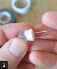
2. Prepare the LED.
Cut about ½" (13mm) off the end of each LED lead, so they’ll fit easily inside the lantern. Use pliers to bend a small dogleg in the longer, anode (+) pin. This will keep the shorter, cathode (−) pin from accidentally shorting out the side of the battery.
Finally, for watertightness, put a single wrap of thread sealing tape around the base of the LED (Figure B).
MATERIALS AND TOOLS
Pipe fittings, PVC, slip-fit, 1": cap (1) and plug (1) parts #447-010 and #449-010, pvcfittingsonline.com
LED, 10mm, diffused lens any color
Battery, coin cell, CR2032
Binder clip, ¾" wide or smaller
Electrical tape, ½"
Thread sealing tape, ½"
Drill press, drill vise, and ⅜" drill bit
Pliers, slip-joint or other blunt-nosed pliers
Wire cutters
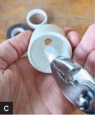
3. Insert the LED.
Place the LED in the pliers so that their blunt nose is flush against the bottom of the LED lens (Figure C). This will let you push the LED firmly without mangling it. Push the LED through the cap from the inside until it’s flush with the inside of the cap. If the fit is too tight using just your hands, use the open end of the plug as a backstop and gently tap the handle of the pliers with a rubber mallet.
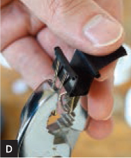
4. Insulate the binder clip.
The enamel coating on the binder clips can insulate but tends to chip. To avoid shorting out your LED, apply electrical tape inside the clip. The pliers can help hold it open (Figure D).
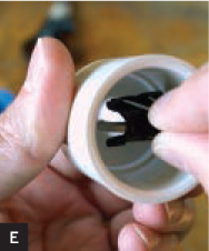
5. Power on.
Slide the coin cell battery between the 2 LED leads, with the smooth (positive) side against the longer lead. The LED should light up. Clip the binder clip over the top to hold the leads securely to the LED (Figure E).
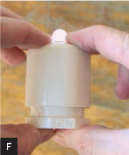
6. Close it up.
Wrap the top edge of the plug once with a strip of sealing tape to keep any water out. Then squeeze the plug into the cap (Figure F).
If you plan to use the lantern in water, make it easier to retrieve by drilling a small hole in the edge of the plug and tying in some fishing line. The lanterns tend to float upright; but if you want them to sink, add some fishing weights or steel nuts before final assembly.
When the battery or LED has reached the end of its useful life, a firm twist will loosen the assembly for replacement.
7. Illuminate.
Use your LED lanterns anywhere you’d like some durable illumination. They’re better in large numbers, and you can vary them to get interesting effects by using flickering or color-changing LEDs.
I’ve used them to light up a yard party and to mark the trail for night hiking. I’ve floated them downstream, frozen them in ice, even used them as ammo in a pneumatic cannon. What you can use them for is limited only by your imagination. ![]()
Steve Hoefer is a technological problem solver in San Francisco. He spends much of his time trying to help technology and people understand each other better. grathio.com

Thomas J. Arey
Mr. Coffee Autopsy
Scrounging parts from a dead coffee maker.
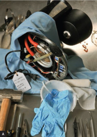
JUST LIKE A BOX OF CHOCOLATES, WHEN you’re scrounging for castoff electronics and appliances, you never quite know what you’re going to get. Take the ever-present home drip coffee maker. I came across one on a recent trash trek (Figure A). It seems that people toss them out when they break the brewing carafe, even though everything else about the unit remains serviceable. Wasteful behavior like this is a boon to the tenacious maker.
![]() CAUTION: Be careful! If you’re not comfortable working with voltages and currents that can harm or even kill, either do not attempt this type of project, or seek assistance from someone who can help you learn the needed skills. Safety first!
CAUTION: Be careful! If you’re not comfortable working with voltages and currents that can harm or even kill, either do not attempt this type of project, or seek assistance from someone who can help you learn the needed skills. Safety first!
Gregory Hayes
When I first encountered a castaway coffee maker, I hoped to just find a small pump and solenoid-controlled valves — a miniature version of what I encountered in my “Clean Out a Dishwasher” article (see MAKE Volume 08, page 146). I was surprised to find a much more elegant system inside this coffee machine. Taking it apart revealed a water reservoir, a heating element, and a mechanism for turning the heating element on.
Water is released from the reservoir into a metal pipe atop the heating element. A simple plastic one-way valve keeps water from returning into the reservoir during heating. The heated water, by virtue of expansion and the bubbles produced by the heating process, rises up into the coffee filter basket and filters through into the carafe. In most cases, this simple heating system is controlled by a timer circuit that works in conjunction with a relay to control the line current, and a thermostatic switch to prevent overheating and control post-brew warming.
No pumps or mechanical valves are involved. So my dreams of using coffee maker parts to power a small desktop “serenity garden” were quickly dispelled (unless I wanted that tiny waterfall to contain boiling water!).
But makers can always find something useful, so I proceeded with the autopsy to find what I could immediately put to use, and what would go into my cache of parts for future projects.
The electrical “guts” of the coffee maker came out in one connected clump after the removal of a few screws.
Immediately useful for any one of hundreds of projects is the transformer. In most cases of scrounged electronics, you’ll find that the transformer reduces standard 110V AC line voltage to something more palatable for low-voltage electronics. Most often you’ll see a single pair of wires on the secondary (low voltage) side of the transformer.
If you see 3 wires (like the one shown here), it usually means that the secondary winding is center-tapped — for example, that the voltage across the 2 outer wires would be a certain value but the voltage across either outer wire and the center wire would read half the total value across the outer 2 wires.
Such was the case with this coffee maker’s transformer, turning 9V into two 4.5V levels. Some transformers have multiple secondary windings. If the voltage ratings aren’t listed on the transformer case, they can easily be determined with a voltmeter.
Also useful for various projects is the relay. This device allows you to switch a circuit on or off with the voltage from another circuit. In the case of the coffee maker relay, the low voltage supplied by the timer circuit would control the higher 110V AC line voltage going to the heating element. Relays have many practical uses, including robotics. It’s always good to have a few in your junk box.
I didn’t have any immediate plans for the heating element so I freed its thermostatic switch from the clip that attached it to the heater. In the coffee maker, this is used to maintain the carafe’s warm state after brewing and to prevent overheating that would damage the unit or cause a dangerous possibility of fire. Again, such a device can be put to work for circuits that warn of high heat conditions.
That brings us to the timer board. Lots of great parts here that could be applied to other designs: 6 momentary switches, 2 LEDs, 4 transistors, 5 diodes, a small digital readout, and the ever-present capacitors and resistors. All good for building fun things. But I backed off stripping the board because, remember, it’s a timer board! While it may no longer be used to brew coffee, it can be applied to turn many other things on and off. Coupled with the recovered relay, it can be repurposed to control higher voltage systems as well.
While the overall part count is low, even a castoff coffee maker can light up a maker’s eyes like a couple of LEDs. ![]()
T.J. “Skip” Arey has been a freelance writer to the radio/electronics hobby world for more than 30 years and is the author of Radio Monitoring: The How-To Guide.