
Unoriented Plastic Films
This chapter reviews the extrusion processes, cast and tubular, that produce unoriented plastic films used in flexible packaging. Basic process sequences for each process are described. The processes on the physical properties of the film have direct effects on the physical properties of the resultant films, even if the initial plastic resin on either process is essentially identical. Process conditions such as draw down ratio (DDR) and blow up ratio (BUR) cause very different crystallinity patterns in films made in the different processes. The differences at this microscopic level are evident in the different machine and cross-direction properties of the film.
Keywords
Amorphous; blow up ratio (BUR); chill roll release; coextruded film; collapsing frame; crystalline; frost line; linear/slot extrusion die; melt flow adapter; modulus; sheeting; surface treatment; tubular extrusion die
A process called extrusion manufactures plastic films. It involves melting a thermoplastic resin with a combination of heat and friction generated by a spiral screw turning in a long barrel filled with resin. The turning screw pushes molten resin out of the far end of the barrel and through a die with a long, narrow gap. A linear die drops (“casts”) the molten resin downward onto a rotating water-chilled drum. It solidifies there and is then wound as a film into roll form. Alternately, an annual die pushes out a ring of molten resin that over time becomes a large plastic tube. If the tube ascends as it leaves the die and air pressure inflates it as it cools in air and a nip pulls it upward, the process is called “blown film.” A tube exiting an annual die downward where a water bath cools it is called “water-quenched film.” Other resources present details of these processes (see “Resources”). This discussion will deal with the influences of the extrusion processes on the films themselves.
Flexible Films
Flexible packaging films are considered by standard industry usage to have thicknesses less than 10 mils (0.01 inch or 250 µ). A material’s rigidity varies with the cube (third power) of its thickness and with the first power of its modulus. Increasing thickness quickly overcomes the inherent flexibility of “soft” materials. Thick materials are considered “sheeting.” With sheet thicknesses, cooling a tube of plastic from an annual die severely limits process outputs, so sheeting is typically manufactured with the cast process. The next chapter, on “oriented plastic films,” addresses films usually extruded in sheet thicknesses, but thinned by stretching to less than 10 mils thick.
Many flexible packaging polymers, with the notable exception of the polyethylenes and its copolymers, are used in both oriented and unoriented film forms. Although equipment and process condition vary greatly, the same basic processes manufacture films with widely different characteristics and uses. The stretching and annealing steps in the orientation process result in films that are stiffer (higher modulus), less elastic (lower elongation), and ready to shrink (back to their original length, width, and thickness) when heated. Figure 21.1 illustrates the dramatic elongation and modulus differences that result from orientation of a 125 gauge polypropylene film. Such property differences are inherently neither good nor bad. Value in use provides the context for choosing one film form or the other.

Cast
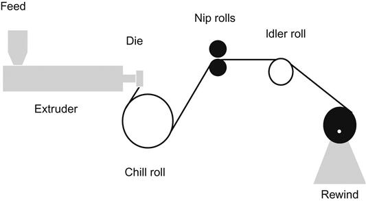
The cast film manufacturing process is very similar to extrusion coating and lamination (Chapter 5). Both utilize a slot die in which molten resin enters in the middle of the top, flows out to the full width of the die, and fills up the center cavity of the die before exiting a narrow die-wide slot at the bottom. To manufacture a cast film, no web-based substrate serves to carry extruded resin away from the die. Rather, the molten resin must solidify quickly on a chill roll (Figure 21.2). Then, in a fraction of a second, the newly formed film releases from the chill roll as nip rollers pull it toward a rewind at the end of the line. “Chill-roll-release” additives are used for copolymers with adhesive affinity for metal. Between chill roll and rewind, corona or flame treatment of film surfaces (particularly polyolefins) may be necessary. Such treatment not only enhances adhesion of the surface in subsequent converting processes, but it also provides a relatively long-lived increase in surface energy so that (for example) aqueous inks and adhesives will flow out evenly on the surface [1].
The cast film process adapts itself to a significant variation (“coextrusion”) that produces a multilayer film. Different extruders can output their respective resins to a “combining adaptor” before they enter the die. The adapter can stack the outputs as delivered, or split the some of the input streams into two or more internal ones and place these on either side of other layers. For example, an adaptor might (1) receive resin from three extruders, “A” with low-density polyethylene, “B” with adhesive tie resin, and “C” with ethylene vinyl alcohol; (2) split the “A” and “B” flows each into two separate streams; and (3) rearrange the flows into a five-layer barrier film of low-density polyethylene/adhesive tie resin/ethylene vinyl alcohol/adhesive tie resin/low-density polyethylene. Using the extruders’ designations to identify layers, the film structure is described as “A/B/C/B/A.” Adaptor technology has developed equipment configurations able to rearrange flows from the various extruders with the result any given line can produce many different coextruded products.
Tubular
Tubular film manufacturing reflects a distinctly different process (Figure 21.3). In the “blown film” variation, molten resin output from an extruder enters the bottom of an annular-shaped die. The die receives the resin and delivers it to the circular opening at its top using an internal channel that spirals upward. At this point, an operator must collect the extruded resin from around the ring and lift it to elevated nip rolls scores of meters above. As the nip rolls begin to carry away the plastic, internal air pressure inflates the tube into a “bubble.” The diameter of the bubble is typically several multiples (up to 8) of the die’s diameter. The ratio of bubble diameter to die diameter is called a “blow up ratio” or BUR. It represents a critical determinant of film properties.
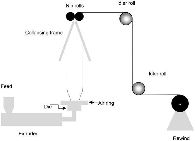
As the molten resin forms a tube, the surrounding air cools it to a solid. In some equipment the air used to create the positive internal air pressure is itself cooled to provide “internal bubble cooling.” At some point above the die, called the “frost line,” the transition from transparent molten resin to a hazier plastic film is usually visible. This hazy plastic appearance does not indicate that the film has completely cooled. In fact, along its entire height, polymer crystallization and other morphological features take place. When sufficiently cooled, a “collapsing frame” compresses opposite side of the bubble together to form a double-layer web. The web can be rewound in this form, or its folded edges slit to produce two single-layer webs each rewound at its own rewinder. Obviously, if the film remains warm and tacky going though the nip at the top of the collapsing frame, the two layers will effectively seal together and cannot be separated into individual rolls. This effect often represents the rate-limiting step in producing blown film (particularly with high ambient temperatures). It can also deliberately produce a double-layer film.
Producing multilayer coextruded films with the blown process is possible, but the technique is not as adaptable as the cast extrusion one. The different extruders must output their respective resins directly to dedicated spiral channels within the die. Resin flows in these channels directly to the circular opening at its top. Only then do they join in the order prescribed by the channels. Changing the order of layers, or their thicknesses relative to each other, involves using different die equipment. Much of the blown film used for flexible packaging is in fact coextruded, but the structure of the films made on any particular line remains essentially constant.
The tubular process for producing “water-quenched film” closely resembles the one for blown film except that a water bath (not air flows) cools the newly extruded film. The rate-limiting influence of ambient air temperature on film cooling does not apply. This often allows higher process throughput.
General Film Property Effects
Cast, blown, and water-quenched film manufacturing processes place very different demands on the molten resins at the molecular level. The ability to maintain a bubble form during blown extrusion demands that the polymer molecules hold tightly to one another and resist the downward force of gravity. A low MFI (i.e., high viscosity) resin provides such behavior. The same kind of gravitational forces tend to pull resin straight down through the die from its entrance point. Again, intramolecular forces and adhesive forces between resin and the die metal must resist gravity. This geometry favors moderate MFI resins with a high degree of side-chain branching.1
The difference in film properties resulting from these different processes exceeds even the scope of differences in the choice of resins. Much of the effects develop as a result of the molecular-level crystallization processes that take place. Crystal formation depends on the external factors of temperature and time. Temperature reflects the energy available to molecules for moving around within amorphous parts of the polymer. Longer times in molten form allows moving molecules to align with “matching” molecular structures, then stop moving when constrained by the intermolecular forces of the crystal structures themselves. Thermal analysis of films can quantify the energy stored in a film’s crystalline structure [2]. The balance of crystalline and amorphous regions in films greatly affects film properties. The relatively slow cooling experienced during blown film formation favors crystal formation. The polymers commercially available as oriented films (Table 21.1) continue to form crystalline structures even at room temperature. Crystallization results in greater stiffness (higher modulus) and more haziness (interference of light by crystals in the film), and less moisture vapor transmission (amorphous areas have higher inherent permeability to moisture). Blown high-density polyethylene film liners (usually coextruded with an EVA (See Chapter 24) sealant layer) provide very economical moisture protection for boxed cookies and crackers. Cast high-density polyethylene film liners twice as thick would not provide as much moisture protection. Cast films, their molecules quickly quenched by the cold chill roll, demonstrate the opposite trends: soft and pliable to the touch with very low haze.2 The cooling of water-quenched films makes these products similar to cast films in these areas.
Table 21.1
Examples of Different Applications of Various Polymers in Oriented and Cast Film Formats
| Polymer | Example | |||
| Cast Film Benefit | Application | Oriented Film Benefit | Application | |
| Polypropylene | High-temperature sealant | Retort pouch | High moisture-barrier print film | Salted snacks |
| Polyester | Oil/grease-resist structural film | Microwavable food | High heat-resist print film | Beverage stand-up pouch |
| Polyamide | Thermoformable structural film | Processed meat | High puncture-resist layer | Military rations |

In addition to the influences of cooling rate and crystallization, these different extrusion processes impose various directional forces during film formation. While these are present to nowhere as great a degree as found in oriented plastic films (Chapter 22), they do affect properties of unoriented films. While crystallization behavior reflects gravitational forces during extrusion, these directional forces lead to variation between machine and cross-direction film properties.
All of the extrusion dies expel molten resin in a form thicker than the intended final film gauge. The ratio of the thicknesses at the die (called “die gap”) to film thickness is termed the “draw down ratio” (DDR). This thinning effect results from force of winding up film at a faster linear rate (feet per minute) than material leaving the die gap. Surface friction on various rolls in the web path (starting at the chill drum) restricts the ability of the warm cast film to become narrower, and the overpressure inflating the tube in that process has the same effect. On the macro level, film thickness trades off for film length, while at the molecular level, the force extends polymer chains and untangles side chains. Linear polymers actually array themselves in the (machine) direction (MD) of the force. Blown films also experience MD forces proportional to DDR, but, unlike cast, they experience cross-machine forces represented by the BUR. These effects result in unbalanced tensile properties in cast films. In Figure 21.1, the MD modulus (i.e., slope of the stress–strain curve) of the cast polypropylene is much higher than its CD value. The molecules align parallel to the machine direction and resist bending against that alignment. In the cross-direction, the lack of molecular alignment makes bending very easy. These same molecular arrangements allow the film to tear more easily in the MD, but resist tearing in the cross-direction.3 The difference can be exploited in stand-up pouches that are fabricated with the sealant film MD across top of the pouch. Once started, a tear across the top should propagate relatively easily and reliably.