
Buildings may last for a long time, but "film is forever"! Revit provides extraordinary advantages for film and stage design professionals, from concept design to construction management. If you're in the film and stage industries (or interested in learning more about an incredibly creative and rewarding design environment), this chapter will give you some insight.
What's really important is learning how to quickly and easily communicate ideas much faster than using traditional 2D tools (which don't lend themselves to 3D) and far more efficiently than 3D tools (which don't lend themselves to construction documentation). Revit has the best of both worlds, and it provides an intuitive, integrated solution that helps everyone involved in the process of making the imagined real.
We'll profile how one set designer in the film industry, Bryan Sutton, has used Revit in his projects. In this chapter, you'll learn to:
Design "scenically"
Use Revit in the design to production process
Use Revit for previsualization
Right up front, you should know that Revit has not widely established a technical presence in the set design industry. Instead, this space is dominated by 3D and SketchUp, Rhino, 3ds Max, and Maya. But Revit has begun making inroads in recent years.
One reason for the recent interest in using Revit in the film industry is Bryan Sutton and his initial posts in the Autodesk User Group International (AUGI) forums in fall 2004. When he posted a few renderings of the airlock door from the first Fantastic Four movie, he immediately grabbed the attention of the growing Revit community.
From that time, there has been a growing interest in using Revit in film and stage production. But of all the designers in that industry, Sutton is considered one of the most talented Revit users not only in his industry but in the world. He has developed a style and approach to Revit that has moved beyond technical proficiency to a masterful art form. That's why we'll share his experiences using Revit with you in this chapter.
Sutton first began toying with computers primarily as a production tool but then quickly began to focus on parametric design technologies. All this was happening while he was working as a carpenter building sets for commercial productions. Some of the first tools he used were AutoCAD, 3ds Max, and Strata. Very soon he started doing production drawings and found he had an advantage in understanding both the set design and the accompanying construction processes.
In Sutton's industry, it's not enough to be technically or architecturally trained. What's important is that you understand how to design "scenically." The design and documentation needs to be suggestive—and what lies beyond the façade should be taken into account.
Sutton's understanding of the importance of designing "scenically" quickly led him to look beyond the traditional 2D CAD tools. So, after starting with AutoCAD, Sutton began to experiment with other 3D tools such as Rhino and IronCAD. It was IronCAD that opened his eyes to the realm of parametrics—the ability to build relationships and affect many changes at once. But the workflow was still lacking an integrated process: what was being designed in 3D was being exported for documentation. And design changes discovered during documentation required editing elsewhere: back to the 3D file, export, and so on.
Fortunately, Sutton discovered Revit from the same friend who had introduced him to IronCAD. He immediately realized that here was an integrated environment for doing architectural work that didn't care where you made the change: 3D, 2D, documents, and even schedules. Sutton was hooked. And he began using Revit 1.0 (just before version 2.0) on set designs for commercials.
In spite of his extraordinary and exceptionally aesthetic approach to using Revit, Sutton is the first to admit that unfortunately he can't "draw himself out of a paper bag." His advice? Hand-sketching is critical for the early design process. You need to be able to draw quickly and elegantly—and according to Sutton, sketching is the language of communicating design ideas.
You can find more information on Sutton at www.imdb.com/name/nm1340613/.
Using Revit in the architectural profession has unique processes and characteristics. The same is true in the production process of film and stage set design. Of course, there's going to be some overlap considering that both spaces need to be occupied by people. But you'd be surprised how little "real" architecture is in the set design industry.
In this section, we'll walk you through the process of using Revit in the film and stage industries. And since you're familiar with the industry, only Revit might be unfamiliar. But if you're an architect already familiar with Revit, the quality and craft of the film and stage industries is going to both impress and challenge you.
Understanding the role of a set designer is easier if you understand some adjacent roles in the production process. Roles that used to be distinct are now overlapping and merging throughout the production process. For example, the director of photography and the director of visual effects used to have distinct roles. The director of photography was traditionally in charge of the production filming, while the production designer was traditionally in charge of the overall "look and feel" of the production. But these two roles are meshing together because of computer-generated imagery (CGI) and visual effects. Both roles should understand the real and virtual sets so that the digital environments have the same look and feel of the physical sets.
Digital tools have reinforced the need to have the entire production team work together in constant communication. Working in 2D can quickly lead to confusion. Even creative people struggle with reading 2D plans, sections, and elevations. Just like in traditional architecture, any miscommunication is expensive in both time and money. And just like with architecture, the production has a deadline—the release date. This deadline cannot move.
Revit offers the ability to provide so much communication in one elegant tool—you get 3D, 2D, visualization, and scheduling in a single environment. But what's compelling with Revit is its bidirectional nature. You can work directly from the production drawings to change the model; you can model in context with a production sketch as an underlay. Being able to quickly and easily create parametric content is key to a successful process.
At the end of the day, Revit is just better organized for creating buildings than using a generic 3D modeling tool like SketchUp, Rhino, or 3DMax. According to Sutton, as a set designer he uses Revit for more than 95 percent of his job, with the occasional modeling in Rhino.
In the following sections, we'll walk you through the process of the overall workflow that takes a project from the earliest production sketches through fabrication and construction.
As soon as the earliest sketches arrive from the art director, it becomes incredibly important to stay away from the "coldness" of computer renderings. They tend to be too hard and lack important emotive qualities—or may even look too finished. You need to focus on techniques to keep the design "loose" early on. This keeps the design open and tends to invite input from the director and others. In Figure 26.1, note how the materials are muted rather than literal representations. Although the glass is transparent, if you look carefully you'll notice there are hash marks on the glass. This is an important graphic gesture. It also communicates materialness in elevation.

This same hand "sketchiness" doesn't just apply to 2D plans, elevations, and sections. Even when rendering, you'll want to overdramatize lighting effects by placing geometry-less studio lights. The gaffer (who is in charge of lighting) and director of photography are keenly interested in lighting effects. So in many cases, you (or more likely, someone else) will need to take a rendering you've created in Revit or Maya and then work on it in Photoshop in order to exaggerate lighting or to soften it. The idea is that you're trying to bring more emotive qualities to the rendering than may be present (Figure 26.2).
Although design teams tend to work on in their own silos (that are focused on different parts of the movie), expect to work in a collaborative environment. Everyone needs to understand how the vision of the art director will allow the movie to flow from one scene to the next.
Illustrators may or may not start with a 3D model. But if they do start with a 3D model, it'll likely be just enough to have provided context for their early design concepts and sketches. Lots of hand drawing will go on top of these images. If you're provided with digital copies of the model and sketches, expect to remodel the geometry because it won't be useful in Revit for more than context. The same goes for the digital sketches. But at least it's a start!
Deadlines are likely going to be very, very tight. Where standard architecture practice allows for months, in the film industry you'll have weeks. And where standard practice allows for weeks, you'll have days. Expect to work 12-hour days, 5 days a week and anywhere from 4 to 8 months for a major motion picture (with a break of a few months between productions). That's not 4 to 8 months for resolving design to documentation—it's for resolving concept to construction. And the detail to be resolved is going to have to be extraordinary, as shown in Figure 26.3.

Construction can start from a napkin sketch in cases when the design is not too complicated. On more complicated projects, it's likely that you'll be working on site and very near to the construction and other production teams—as in the same building, down the hall, or possibly in the same "war room." Some pieces of your design may be repetitive and contain parts that have to fit together with a high degree of precision. When this is the case, it's likely these pieces will be prefabricated via CNC and then assembled on site. Fortunately, you can export other formats from Revit that quickly lend themselves to fabrication (such as *.sat or ACIS).
Sutton has worked on a number of "third-act" sets. Third-act sets are known for being large, complex, and/or highly themed because they'll be seen near the end of the movie and must leave a lasting impression. In the case of Watchmen, the Karnak set took months to create, and the Revit model was used to resolve issues ranging from design to camera angles to rigging for stunt work (Figure 26.4). Overall, remember that it's critical to stay a week or two ahead of the construction team because of the amount of lead time required by the set decorators after construction concludes.

Even with all the early attention to detail during the design process, occasionally parts of sets will need to be pulled apart and rebuilt. But keep in mind this is extremely disruptive to the entire production process. The deadline has been set years in advance, and the budget is inflexible. The tolerance for rebuilds is becoming more unlikely now that 3D is becoming so common in the design process.
While quantities are important, in the middle of all this design iteration and visualization production, some standard architectural techniques may not translate into designing for film and stage. For example, it's unlikely that you'll be creating discrete schedules as you normally would. So rather than noting quantities on schedules, you'll tend to note them on sheets. This makes it simple and keeps as much information in one place as possible. You'll also indicate spacing—but again not the hard numbers.
In the same way that traditional architectural schedules aren't used (but rather, quantities are noted in context with documentation), details are shown in the context of the elements being detailed. So, rather than "segment" your work into different groups (plans, elevations, sections, and so on), it's more likely that you'll be assembling your work in context, which is more like traditional architectural hand-drawn techniques. For example, being able to see both design intent and resolution at the same time is important. Plans, elevations, sections, and 3D views will likely be assembled together (not apart). This is particularly true as set builders can be given a lot of creative leeway, and you're often giving them enough information to get started. Prop builders, fabricators, and sculptors—they all love to have 3D representations! Taking an artist's sketch and putting it in context of the construction documents communicates the spirit of design intent (Figure 26.5).

While we're discussing documentation, remember that dimensions in context with shaded views are better suited for resolving depth than mere hidden line views. Much of what you'll be designing in film and stage production are curved, imaginative kinds of forms. These shapes aren't visualized well in black and white, 2D kinds of views. But if you change the views to shaded, curved elements are far more expressive. If you need to embellish 3D and perspective views, simply add the text and other notes outside the view once the views have been placed on the sheet.
Be sure to demonstrate finesse with regard to visualization that is suitable for communication as well as presentation—and sometimes these are different things. In other words, how you illustrate design intent comes in many styles and influences. But what's important is to be able to make deliberate design decisions while illustrating a certain aesthetic lack of resolution. Because so many people are going to influence the final product, you must visualize your work in a way that doesn't raise unnecessary objections while building consensus as quickly as possible.
Level of detail is critical in the film and stage industries. Don't expect to model to the level of detail standard in architectural practice. In other words, you're not going to be able to model in 3D at a low level of detail and then document in 2D a greater level of detail. If the component calls for hardware, you'll probably model it. In this industry, geometric detail is vitally important. It'll be leveraged for documentation through visualization. What you model is what gets built—you're not going to be allowed to leave much if any to guesswork or imagination (Figure 26.6).

Fabrication is essential. Computer numerical control (CNC) plays a large part in the set design industry and utilizes five-axis machining, laser cutting, and water cutting (which was used to create the lattice work in Figure 26.7 and the door panels in Figure 26.8). Speed and accuracy are huge benefits and provide unmatched precision for preassemblage.


Five-axis tools usually mill high-density foam "sign board" if a more finished surface is required. If the surface needs to be less finished and a bit more porous, less dense Styrofoam is used (typically used for simulating concrete).
But for very tight, automotive-quality finishes, CNC machines are used to make the molds, which are then treaded and used as negatives for fiberglass casting, a process that was used to manufacture the "Fantasticar," as shown in Figure 26.9. And although Revit wasn't used to model the Fantasticar, it was used to model the dashboard elements that were used in the car—and its garage.

Figure 26.9. "Fantasticar" garage and support elements from Fantastic Four: Rise of the Silver Surfer
Geometry modeled in Revit will usually be taken to Rhino for unfolding a developable surface—like the airplane fuselage for Snakes on a Plane. But the structural ribs that were modeled in Revit were resolved by water cutting (Figure 26.10).

Some of the differences that you'll encounter in the film and stage industries compared to architecture will resonate when you get to construction. This is not to say that architectural projects aren't highly detailed—just that they're detailed differently. In film and stage production, you'll model not only what will be seen but in some cases what will not be seen. For example, when modeling, take into account the green screens beyond the actual sets as in Figure 26.11. Being able to accurately previsualize their size and locations during the design standpoint is important.

Remember that when you're designing "scenically," you're going to be focusing on maintaining the emotive quality of the design without getting into too much detail. As the design progresses, geometric "intent" will give way to specific content. But even then, someone will take over what you've started and give the final look and feel to your work. You're not just trying to show the literal "geometry" of what needs to be constructed—you're also trying to maintain the emotive quality and connection to the earliest production sketches.
Concentrate on illustrating differences between what is solid and what isn't. The context of what is beyond the immediate space is important. Note the equipment in the room beyond the center space. For example, in Figure 26.12 the materials in Reed's science lab are muted and suggestive—but not too literal. Color is used to distinguish between different materials rather than to express specific materiality.

Surprisingly, Bryan Sutton doesn't keep a project template. He says not starting from a template "keeps it simple." However, details are often reused, and Sutton has created a set of custom line styles to indicate "wild walls" (where the walls have deliberately designed breaks so they can be opened for camera access).
Components and system families are not typically reused from project to project in the film industry—everything is highly customized from project to project (unless a sequel is being considered). Rather, Sutton uses a more elegant process of employing generic elements as placeholders during the early design stages. These component and system families are sufficient to indicate the design intent of placement, spacing, and locations—the "big ideas" of the design. As the design is refined, he'll swap out the placeholders with more specific elements that share the same category and insertion point. Being able to swap out one "idea" for another quickly and easily is something that Sutton remarks "is what's really nice about Revit."

Even before materials are assigned, lighting plays an important role in adding emotive, dramatic context to the design. You have a couple of options since Revit allows shadows in real time but only a single light source, as illustrated in Figure 26.13. Beyond this you're going to need to render.
While the objects in Revit can contain the actual "lights" that can be controlled at time of rendering, this may not be enough. So keep in mind that studio lights (lights without lighting fixtures—just the light source) can be added to the project as well, a technique that was used to visualize Figure 26.14. These kinds of lights are useful for overdramatizing lighting effects and overcoming otherwise hard edges of shadows at the time of rendering.

When materials are added, they're probably going to be understated during the design process. More detailed and specific materials assignments will be assigned by CGI artists (who will probably benefit from using your files as a starting point). In Figure 26.15, the horizon is being subtly suggested—but not as a hard, horizontal line in the distance that separates earth from sky. Any more detail would be a distraction!

Renderings are critically important to the design process in the film industry, and you'll have to communicate simultaneously with regard to form, space, lighting, material, opacity, transparency, and so on, as shown in Figure 26.16. But in some cases, you'll want to be able to render one theme at the exclusion of others.

Rendering conceptually as any solid color is a quick way to rationalize and objectify the design. This can be quickly and easily done in Revit using phasing. All you need to do is create a new phase filter called Matte Rendering. Be sure all the phase filter assignments are set to Overridden. (To learn more about phasing, see Chapter 11, "Phasing, Groups, and Design Options.") This is shown in Figure 26.17, as phase filters are being overridden; Figure 26.18 illustrates material assignments associated with a particular phase.


Using the Phasing dialog box, set the Graphic Overrides values of both shaded and rendered material assignments of the Complete phase to a solid, white (or off-white) matte material, as shown in Figure 26.19.

Create a 3D View, then open View Properties and set Phase Filter to Matte Rendering. Figures 26.20 and 26.21 show the results (before and after).
When you render with these settings, the result will be a monolithic scene that doesn't require you to manually manipulate the materials one by one for shaded views or renderings.
Keep in mind when using this technique that glass will render as opaque. If you want to render with glass as translucent, you'll want to render twice and create a composite view. First, turn off any glass via Visibility Graphics (Categories or Subcategories), and then render the view. Now create a composite view with the glass turned both on and off, and then set the transparency of the view with the glass turned on to around 20 percent. Figure 26.22 shows the final result.


Creating a hidden line composite view is just one more step beyond creating a composite rendered view (Figure 26.23). Hidden lines are helpful for distinguishing objects that are small, translucent/transparent, or at some distance from the viewer because they accentuate the edges of objects. In these cases you can export a hidden line view and then overlay with a rendered view in order to accentuate edges (Figure 26.24).
With this kind of composite view, it's easy to see why they're so effective and desirable. In Figure 26.25, it's apparent that important details are missing! But in the next image, the details are clearly visible through highlighting the edges of those objects from an exported hidden line view (Figure 26.26).

Figure 26.23. Hidden line export

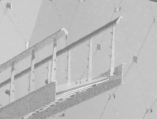
Figure 26.25. Detail before hidden line composite

Figure 26.26. Detail after hidden line composite
Photorealistic renderings are certainly important to the design process as a set designer, but if your work is meant to resolve constructability, it may turn out that you're not responsible for creating highly emotive, finished views. Be aware that from within Revit, you are limited to the geometry that is in the Revit file.
But even if Revit were capable of creating any form imaginable, keep in mind that another person needs to render in their language of choice. And after years of fluency in one language, it's not likely that they're going to change languages to render in Revit. Additionally, they'll subject their renderings to significant postproduction in an image editor. So, be prepared to work with the visualization specialist by exporting Revit to another format (DWG, 3DS, FBX, and so on).
Live exploded 3D views can be quickly and easily assembled in a couple of ways. The first technique involves creating a section box around part of your project and then selecting and copying this section box (Figure 26.27). Copying a section box automatically creates another section box with the same view.
Another option is to isolate elements in duplicated views (with or without a section box). When you assemble the views together (on a sheet) you'll be able to pull them apart, creating the effect that the object is being pulled apart. This will help illustrate individual elements that will be prefabricated for assemblage.
According to Sutton, the film and stage industries in Vancouver overwhelmingly use Maya. And before FBX exporting, getting your file to a usable format wasn't always too successful. Fortunately, FBX has really helped. But in some cases you'll export to 3DDWG (and usually as ACIS solids). Autodesk Mudbox is frequently used for high-resolution close-ups (ZBrush).
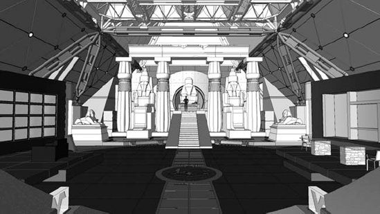
Your Revit file is often a useful starting point for the CGI work that complements the physical sets, which can be exquisitely detailed, as in the Karnak main hall in Watchmen (Figure 26.28). What's nice is that everything should line up between the physical and digital designs. But don't be alarmed if much of your work needs to be "rebuilt" in Maya.

Stacking Views
You should anticipate how the views should stack. It's not yet possible to reorder the front/back relationships of views after the views have been placed on sheets. So the views in the "background" need to be placed on the sheet first and the views that need to be in the "foreground" should be placed last. The image shown here displays the real-time exploded views through the airlock on Fantastic Four.

First, people like to have full control in a familiar "language" (application) that they have used for years. The deadlines are demanding and there's no room for unpredictable outcomes. Since Maya is being used extensively in the industry, it's likely that Revit files will get leveraged in Maya.
Second, the level of detail that you've produced in your Revit file (you know—the level of detail that is way beyond standard architectural practice) will likely be unnecessarily high for the CGI artist, as illustrated in Figure 26.29. Rendering is still incredibly expensive and time consuming. So any shortcuts to shorten rendering times (without sacrificing quality) are welcome. As a result, the CGI artists often use materials to represent granular geometric details—the kind of details that you've just modeled with geometry in Revit to resolve construction (Figure 26.30)!

Best practices for using Revit in the film and stage industries may have a lot in common with standard architectural practices, but sometimes they'll be significantly different. We'll cover both the similarities and the differences in the following sections.
As mentioned earlier, the level of detail that you will model in these types of projects will greatly exceed what is customary in a standard architectural project, where a high resolution of detail is either not necessary for construction or is resolved in 2D with detail components during documentation. In this industry, modeling generically in 3D and then attempting to show more detail in 2D can be a distraction to an exacting art director. So don't be surprised if you're expected to model to less than an inch in detail—and expect what you model to be a fairly literal representation of what will be built.
Maintaining flexibility during design is critical to a successful project because once production starts, everything starts moving quickly. Use generic representations of an approximate size and category. As the design progresses, you can easily swap these "design placeholders" out for more specific elements.
In the film and stage industries, phasing and design options will also be used in 3D and documentation views to illustrate alternatives where pieces of the set need to convey some sort of movement—for example, if an object needs to be opened and closed or extended and retracted. In this case, simply assigning a unique phasing or design option to those elements will allow you to filter the views to only show one condition or another at a time.
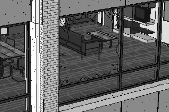
In the case of the Comedian's (Eddie Blake's) apartment in Watchmen, phasing was used to illustrate the shattered curtain panel. The existing panel was unbroken, while the proposed panel was shown in the broken state (Figure 26.31).
Nesting is extremely useful for creating a component once and then using it in many different components (Figure 26.32). The advantage is that it's significantly faster (sometimes more than 95 percent faster in some cases) to update family components rather than groups. Keep in mind that a lot of the elements that you'll model will themselves contain nested components. This allows you to manage and update repetitive relationships quickly (Figure 26.33).


Choosing the right family category is also important, but not in a way that often comes up in standard architecture practice ("Hmm...furniture or furniture system?"). Most of the time, the Generic Model category will suffice. But there remain a couple of subcategories that are really important.
First, you will have to select a Lighting category if you anticipate using the component to render lighting effects. Second, use face based rather than hosted.
Either face-based or hosted components can "cut" their host. With a face-based family, you need to model a void to cut the face, whereas with a hosted family, you must add an opening or a void. That's not so much of a difference, right?
Wrong. If you select hosted, you need to also know what kind of host is going to be cut (Wall, Floor, Roof, or Ceiling). But in this industry, what is a floor one moment might be a ceiling the next. And what is a wall today may turn out to be a roof later! So, specifically selecting a hosted category (which requires you to know what sort of host is going to be cut) can lead to disastrous results when the design changes (and it will...a lot)! Using a face-based family avoids this nasty consequence.
Another reason is that face-based families will easily orient themselves to the face of either component or system families, whether in the project or a nested family environment.
Finally, a face-based family can cut the face of both system families (in a project environment) as well as when nested into another component family. Overall, face-based families offer a lot of flexibility during the design process.
Keep in mind that in many cases nested components are likely to end up in multiple families as well as the project environment. This adds another layer of complexity when you find yourself in the awkward situation of having to open and edit multiple families in order to make whole project changes to a nested component. This is where "sharing" the parameters of the nested components will save you a lot of time and trouble.
Here's how: if you expect that the nested family is going to be nested into other families—or used directly in the project—you'll want to consider setting the Family parameter of the nested family to Shared (Figure 26.34).

Simply select the originally nested component and edit its Category And Parameters setting. Select the Shared option and then reload this nested component in your family. The next time this family (containing the nested and shared component) is loaded into your project, both the component and the nested/shared component are loaded into the project. Whenever you edit this special shared/nested family (from either the project or one of the many families it's nested into), it will update everywhere in the project.

Modeling complex forms in Revit often differs from modeling in other 3D applications. Think of sculpture. First you can create something by building a formwork and then casting what you want within that form. This is an additive approach.
In Revit, the process, sculpturally speaking, is more subtractive. In other words, the complex form that you're trying to create is going to be accomplished by creating more geometry than necessary and then "carving" away the results with a void. This can be accomplished by building up "layers" of geometry (and perhaps joining them). But when you add voids, selectively cut only certain layers of the geometry.
See Figure 26.35 for a simple example. Although the family looks complicated, it is composed of only five elements: two solids and three voids. This file is also available for download from the Chapter 26 folder as the Complex Cube.rfa file.

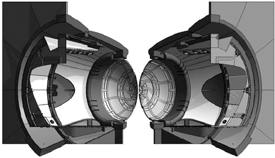
Carving geometry to resolve a desired shape is a simple technique but absolutely essential for being able to quickly create and (more importantly) iterate complex forms in Revit, such as the airlock door in Figure 26.36. According to Sutton, nonlinear solid/void relationships give Revit the edge over other more generic modeling tools (Figure 26.37).

The file of the airlock door (Airlock Door.rvt) is also available for download from the Chapter 26 folder. It's a great example of using overlapping solids and selectively placed voids to cut away portions of geometry while leaving adjacent solid geometry intact. This technique was skillfully used to cut away the reveals that surround the airlock door (Figure 26.38).

Worksets are typically not needed in the film and stage industries unless the project is large or contains a campus-like collection of other Revit projects. Although this atmosphere is highly collaborative, it's also task-centric—one person dedicated to working on one part of the project or file is not uncommon. So, using worksharing to distribute Revit files across multiple team members is not common.
Having worked in the film and stage industries using Revit since 2003, Sutton has successfully managed a number of design challenges. The following are just a few production-related stories.
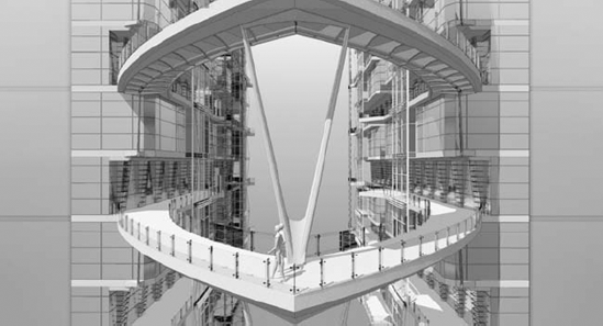
I, Robot was Sutton's first feature film and really quite special. After working for a number of years in set design at the scale of commercial production, it was "trial by fire." The sets were much larger, as well as multistory, as shown in Figure 26.39.
Sutton had to take over from an architect, and in some cases, the drawings were hard to read. In other cases, one design view would not align with another view, and in this industry coordination is extremely important because of the short deadlines.
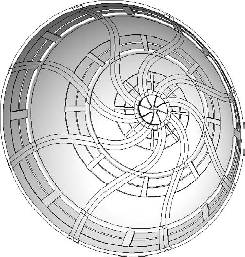
In Sutton's words, "Revit really saved the day." Views were always consistent and always agreed with each other. The precision was always there, even considering the detail in the access walkway and platform surrounding the computer core (Figure 26.40). Revit was used to count the number of spider brackets used for the railings and other hardware.

Ultimately, the VIKI brain that had been modeled in Revit for constructing the physical sets was leveraged for CGI work. This gave the CGI artists some great starting points (Figure 26.41). Again, precision was key.

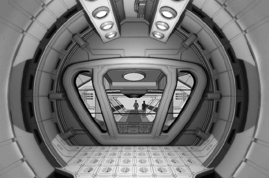
Fantastic Four was the next feature film that Sutton helped design in Revit. In this project, the level of detail increased because so many renderings were being done directly in Revit for this movie, starting with the interior of the space station (Figure 26.42).

Of course, these were the days of AccuRender—and many extra studio lights were placed in order to avoid the hard shadows that were common at the time. The shadows in AccuRender had hard edges and required a lot of artificial lights placed around the space, especially considering the detail and lighting of the ceiling (Figure 26.43). Fortunately, the implementation of Autodesk mental ray has improved the process.
The ceiling was challenging to model, according to Sutton, because there were so few straight lines. But he was able to do it with Revit using a lot of built-up solid and void relationships. The sweeps going along the edges of the ceiling and down to the floor was particularly challenging, as shown in Figure 26.44.
When you can't get the model "just right," you have the geometry as context for documentation. This saves a lot of time over the back and forth compared to modeling in 3D, exporting, and then documenting in 2D.


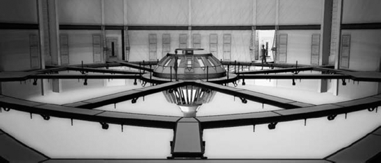
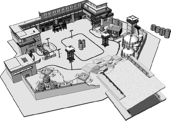
This project built on the challenges of the previous projects. Sutton soon found himself being selected to design the third-act set (see the section "Lead Time and Production" earlier in this chapter). The island of Alcatraz was going to be third-act set and would be used for the big fight scene at the end of the X-Men film. It turned out to be an interesting challenge, because it involved a lot of both indoor and outdoor sets, such as the exterior Alcatraz set (Figure 26.45).
Fortunately for the third-act set, you're likely to be given a bit more lead time. It's got to be detailed—and it's going to be used for a lot of the "money shots" at the end of the movie. For X-Men, it also had to include a debris field that was supposed to suggest the ripped apart end of the Golden Gate Bridge (Figure 26.46).

Originally, for Snakes on a Plane, actual pieces of aircraft fuselage were going to be used in context of the set pieces that remained to be built. So, the new challenge was integrating pieces of actual planes into Revit for context. But in the end, they rebuilt the plane and gutted the existing plane for parts and set dressing (Figure 26.47).

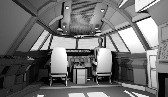
Some of the 3D shapes were a challenge. For instance, the fuselage consisted of complex shapes. But in the end, nearly the whole plane was designed in Revit, even the cockpit area (Figure 26.48). Overall, it was a "smaller" production.
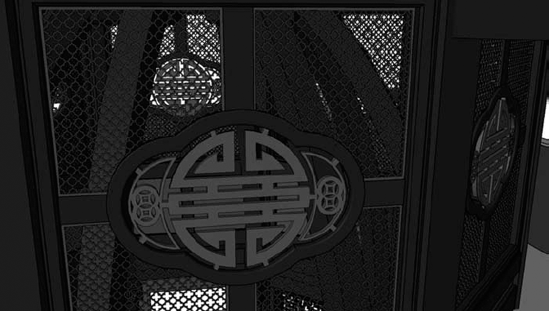
This project was rewarding—the people working on the project were great. According to the production designer, Revit helped "save the movie." The set pieces, like the highly complex and detailed pagoda shown in Figure 26.49, required intricate structural elements and carefully cut screened panels.

In the case of the pagoda, full-sized sheets were printed and used as stencils for cutting the lofted, structural ribs. In other cases, CNC machines were used to cut out the door and panel pieces designed in Revit (Figure 26.50).
For this movie, numerous set pieces were designed in Revit. But there was one particularly interesting challenge: a replica of the Wright Flyer, as shown in Figure 26.51, the world's first powered aircraft to achieve controlled, sustained flight. Apparently a company exists that makes replicas for museums and other displays. In this case, though, the replica needed to be 85 percent smaller than the original. Oh, and the wings had to have proxy elements built of fiberglass so that the actor could walk on them during production.
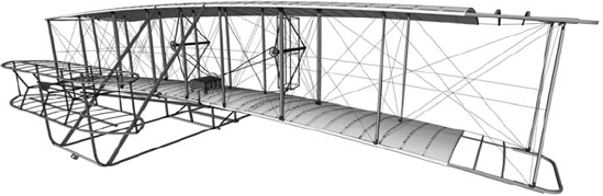
While reviewing copies of drawings originally from the Smithsonian, Sutton wasn't sure that it could be done in Revit. The detail in the drawings was extraordinary. But once he began to visualize and understand the parts that made up the whole—the ribs, the frame, and the engine—it all became quite clear. And in the end, according to Sutton, it was great fun modeling the Wright Flyer in Revit.
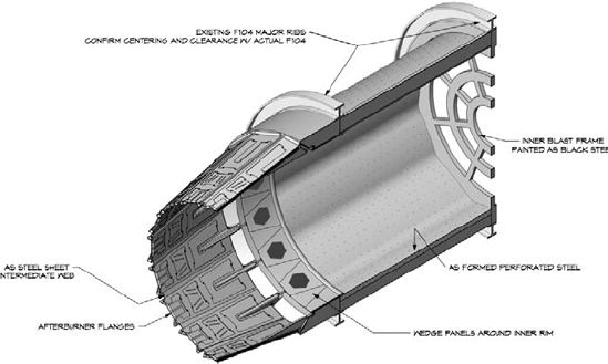
In fact, in addition to the air and space set, even smaller details like the afterburner for the F104 was modeled in Revit (Figure 26.52).
Watchmen is a graphic novel (originally released as a limited 12-comic book series). It was created by writer Alan Moore, artist Dave Gibbons, and colorist John Higgins and published during 1986 and 1987. Although attempts to create a live action film began shortly after the graphic novel's success, some deemed the complex narrative "unfilmable."
Numerous production starts and stops continued until Warner Brothers brought in Zack Snyder (the director of 300) and principal photography began in 2007. Snyder even created his own storyboard sketches to fill in the action between the key frames of the novel. According to Sutton, "It was fantastic working for the director who creates his own version of storyboards. He has a very visual approach. I actually used the sketches for reference within the context of the design and construction documentation."
Another detail that Sutton looked forward to during the Watchmen film and production was the opportunity to work with Alex McDowell, the production designer (McDowell's previous efforts include Fight Club and Charlie and the Chocolate Factory). Sutton had long admired McDowell's work.
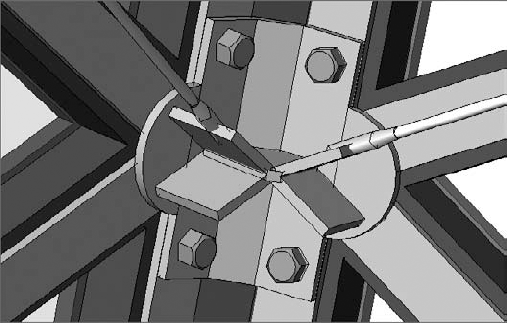
The Karnak set was the third-act set and would be extremely detailed. At the direction of McDowell, the bolt heads were modeled in Revit with chamfers (Figure 26.53).
Once again, phasing was used extensively to turn off and on large portions of the model to visualize the various stages of construction and production. The glazing system was also extensive.
Ultimately, the model was so complex that major portions of the model were done as large collections of nested families, as shown in Figure 26.54. This was done to manage the amount of highly detailed repetition.

Creating individual families and then nesting them into a single, large family maintained design iteration. This large family assemblage was then loaded and placed into the project (Figure 26.55). Admittedly, families of this scale might not be a standard architecture best practice, as it would obviously affect scheduling. But the advantage to the exception in this case is pretty obvious. Rather than creating separate projects and linking them together, you're creating really large families and loading them into the project. (Figure 26.56).


Design iteration could then be managed by opening the "master" family and then drilling down to get to the single nested family, as in Figure 26.57. Then the nested families would be reloaded into the master family. Then this master family would be reloaded into the project file, illustrated by the single cell in Figure 26.58.


- Design "scenically."
According to Sutton, profiled in this chapter, designing "scenically" takes precedence over designing too literally. This might be different from standard architectural practice, but it's critical in the film and stage industries.
- Master It
How would you design "scenically," and how does this differ from standard architectural practice? What can you learn from the film and stage industries to keep the emotive quality high?
- Use Revit in the design to production process.
While standard architectural practice entails design to documentation, the film and stage focus is from concept through construction.
- Master It
With an emphasis on level of detail and tight, repetitive elements and finishes, what would you do to help maintain time and budget? How might you suggest creating intricate repetitive design elements in your next project?
- Use Revit for previsualization.
When using Revit in the film industry, you need to keep the design "loose" during the early concept stages. You'll have to match the look and feel of the art director's vision. Keeping the materials muted will be far less distracting than being too specific. One of the great things about Revit is that you'll be able to emotively visualize in the same environment as you analytically rationalize. This will come in handy when the director, director of photography, and then art director all want a different question answered at the same time!
- Master It
How can you express constructability to a high level of detail, particularly when the object is going to be assembled from many individual parts? Why rely on standard architectural practice of documenting in plan, section, and elevation views?