Chapter 8
Advanced Modeling and Massing
Every design starts with an idea. That can be shapes drawn out on trace paper, or a chipboard model, or a conceptual form in a 3D model. This idea becomes the basis for your design and ultimately your building. Although you might sketch out several variations to give your ideas shape, there comes a point in the design process where you need to begin testing your assumptions. Does the floor plan fit within the building’s massing? Does it meet the client’s functional requirements? Is the design energy efficient?
Massing is a set of unique tools within Autodesk® Revit® Architecture software specifically created for this kind of early design analysis. By creating the “big” design idea at a macro level, you’re able to quickly and easily quantify and analyze the results. This allows you to confidently work from general to specific as your design progresses, without concern about actual building elements.
In addition, the massing tools allow you to create forms and containers to control other building system components. Complex walls, curtain walls, curtain panels, and other elements would be incredibly difficult to make and update without some underlying form to establish and drive their design.
Even though your overall design might not be represented by a complex massing form, it’s likely that somewhere in a more conventional design, massing is essential to the success of your project.
In this chapter, you’ll learn to:
- Create and schedule massing studies
- Know when to use solid and surface masses
- Use mathematical formulas for massing
The Massing User Interface and Functionality
A mass is simply a form with geometric substance (solids and voids) that is not related to any specific building element category. It is intended to allow designers to create a lightweight component that can either represent an entire building or serve as a guide for a single component, such as a complex roof form. When you create a mass in the context of a whole building, you can quantify the surface area, assign functional “floors” to the mass, and perform energy analysis—all without creating a single wall, floor, window, or roof.
After you create a whole-building mass, you can use By Face versions of commands to place system families such as walls, floors, and roofs. When these elements are placed by face, they retain a relationship to the mass elements. The associated building elements are not updated automatically, which means you can freely explore design alternatives to the massing. Once you are confident of your final design decision, the building elements can be updated to match the changes in the underlying mass.
Another important thing to know about massing is that masses can be created in either the project environment or in the Family Editor. Much of the functionality overlaps in each case, so what’s the difference between the two?
The main difference as to whether you create massing in place or in the Family Editor doesn’t depend on the kind of shape or surface you want to create. Solid and surface forms can be created in both the project and Family Editor environments. Rather, it depends on how you want to create the massing and how you want to change the mass once it’s been created.
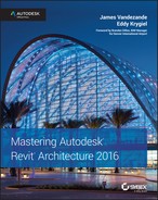
Using in-place masses gives you the ability to model in the context of other surroundings (Figure 8.1). For example, you may be proposing an addition to an existing building or a new building on an existing campus. You may need to create a complex shape for a feature wall or a roof form, and you therefore need the context of the rest of your building design.
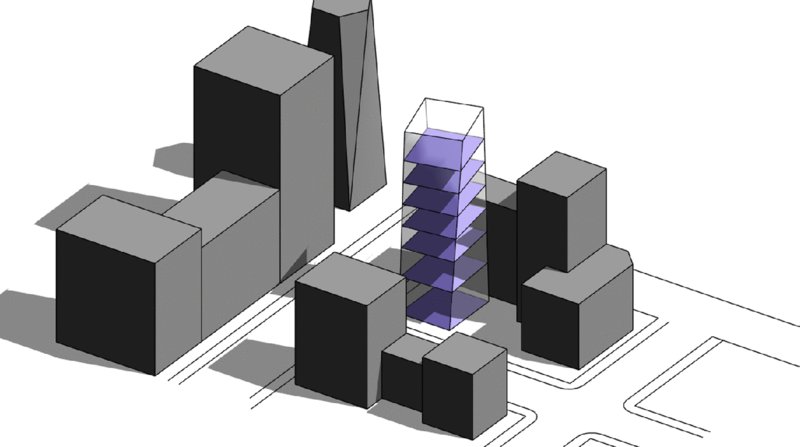
Figure 8.1 Building massing in the context of an existing neighborhood
Creating a mass in the Family Editor gives you a slightly different user interface (UI) (Figure8.2). When you create a Conceptual Mass family, you have the ability to see work planes and levels in 3D views; however, these references are not in the context of your project environment. In addition to the lack of context in the Family Editor, to make changes to massing, you must reload the mass families into your project for face-based elements and schedules to update.
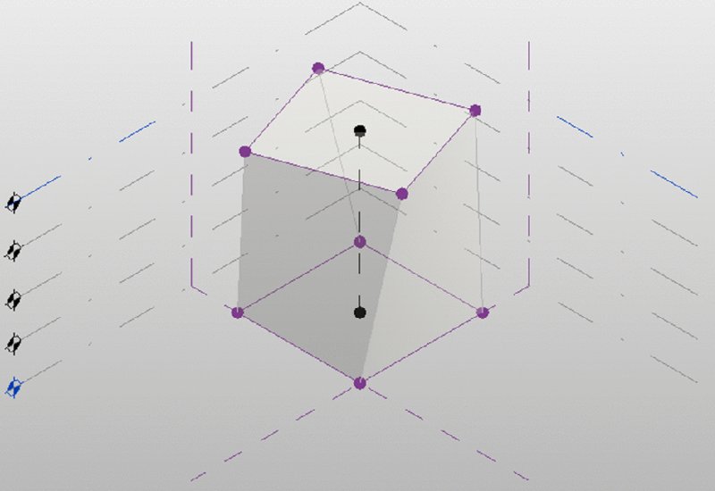
Figure 8.2 Building massing in the Family Editor
Let’s take a moment to clarify the difference between in-place component modeling and massing. If you need to create a custom-shaped building element, such as the wall shown in Figure 8.3, you would use the Model In-Place command. You would set the category to Walls and then use either a blend or a sweep to generate the form of the wall. You’ll notice in the figure that the sectional dimensions of the wall are not consistent.
Figure 8.3 Custom-shaped wall as an in-place element
If you wanted to use a wall assembly with consistent sectional dimensions but configure the wall in a complex vertical layout, you would create a mass and then use the Wall By Face command. In the example shown in Figure 8.4, a generic wall is applied to the face of a mass that was created by generating a surface between two splines.
Figure 8.4 Standard wall type applied to the face of a mass
The rest of this chapter will focus solely on the creation of masses for the purpose of whole-building design. You can learn more about component modeling tools in Chapter 14, “Designing with the Family Editor.”
Creating Mass Geometry
How you create masses (surface or solid) differs significantly from the UI used to create other standard family content. When you’re creating standard project content, you have specific geometry tools such as Extrusion and Sweep (Figure 8.5). In some ways, this is a noun-verb approach: You select a tool for the form that you want to create and then you take action to create it.
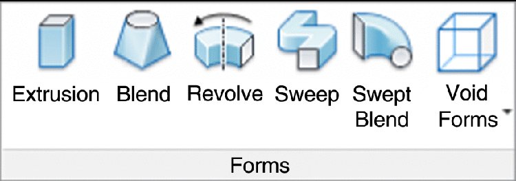
Figure 8.5 Non-massing form-creation tools
Creating a mass still requires that you know the form that you intend to create, but you’re not required to select a particular form type to get started. Rather, you start by simply creating the sketch-based elements that would define your shape. Then you select them as a group and choose the Create Form tool (Figure 8.6). This will allow you to create both solids and voids.
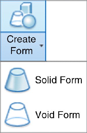
Figure 8.6 The Create Form tool
Both solid and surface may be created from model lines or reference lines; however, the differences are important. Keep in mind that your ability to further iterate the form that you create depends on whether you use model or reference lines to generate the form, even though the forms created may look exactly the same at first.
If your intent is to simply create a form that is not likely to require rule-based parameterization, using model lines is fine. Model lines are consumed by the form after you use the Create Form tool. In other words, the only way to get back to your original sketch form is to dissolve the shape. But if you intend to control the form with formulas and other parameters, it’s best to start with reference lines. Figure 8.7 shows the subtle graphic difference between the two line types. The model line shape is on the left, and the green reference lines are on the right. You will also notice that when reference lines are selected, they have much more capability to serve as multidimensional references for hosting other geometry.
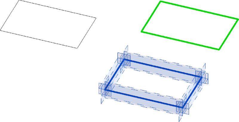
Figure 8.7 Model lines and reference lines
Because the difference is so subtle on the screen, we recommend that you give your reference lines more thickness and lighten the default green color so that they stand out better, and make that a part of your project template.
Creating an In-Place Mass
Now that you are familiar with the difference between massing for components and whole-building massing, let’s look closer at the important capabilities that will help you develop building designs. Download and open the file c08-Massing-1-Start.rvt or c08-Massing-1-Start-Metric.rvt from this book’s website at www.sybex.com/go/masteringrevitarch2016. In this section, we will create some simple mass forms, generate mass floors, and then build schedule views to quantify the results. After you open either file, activate the Level 1 floor plan before starting the exercise.
Whether you create masses in place or in the Family Editor, you’re able to generate floor faces (not the actual floors) and schedule important metadata before you’ve even begun to assign actual geometry to the masses. This is important to do early in the design process because the masses will be “light” in your project—they won’t have a drastically negative impact on performance. Use them to establish your overall design idea and get a general idea for building size and area.
In-place mass forms can be both solid- and surface-based forms; however, masses that contain only surfaces cannot be analyzed for any sort of volumetric quantities. You can start an in-place mass in one of two ways: The first way is to select the Architecture tab in the ribbon, and on the Build panel, choose the Component ➢ Model In-Place command.
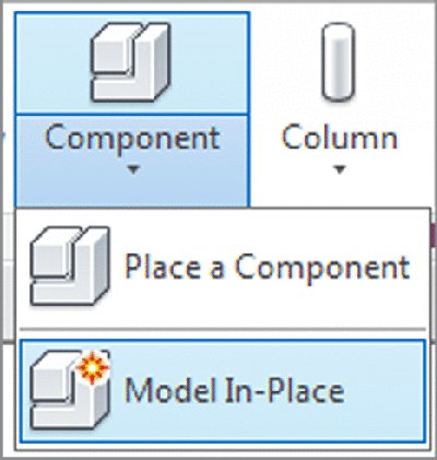
When you select this option, the Family Category And Parameters dialog box appears (Figure 8.8). You will be able to use the other massing tools only if the in-place component is assigned to the proper category. Be sure to select the Mass category and click OK.
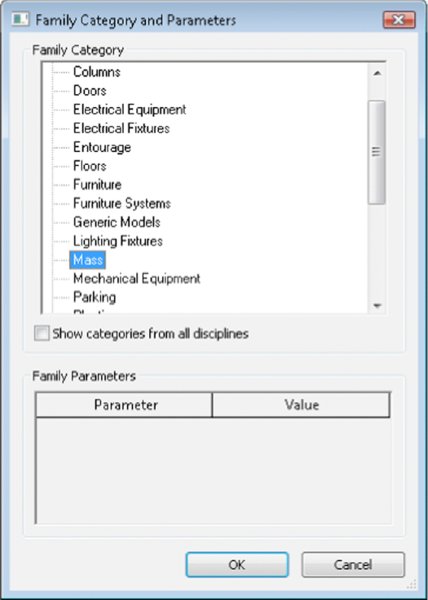
Figure 8.8 Selecting the Mass category
 The other way to create an in-place mass is to select the Massing & Site tab in the ribbon and from the Conceptual mass panel, choose the In-Place Mass command. In either case, when you start to create the mass, you’ll want to have the Mass category visible (it’s turned off by default in all views). Rather than confuse you by allowing you to create objects that wouldn’t be visible, the software prompts you to turn the category on (Figure 8.9).
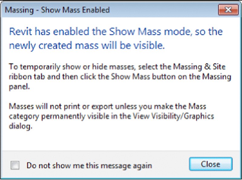
Figure 8.9 Enabling the Show Mass mode
Once you close this dialog box, you’ll be given the opportunity to name your in-place mass. In this case, you’re going to name the mass Cube (Figure 8.10).
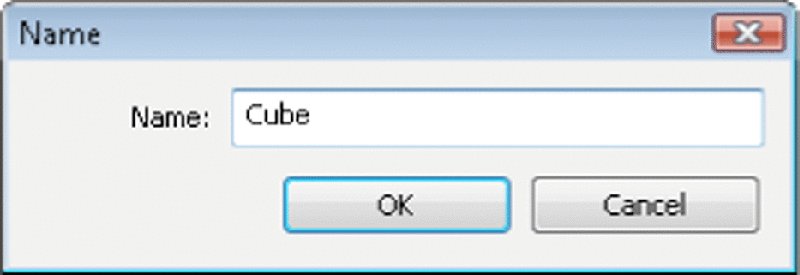
Figure 8.10 Naming the mass
After you’ve named the mass from the previous steps and clicked OK, you’ll be shown the Massing toolset for in-place families. The Create tab contains the tools that you’ll use to create solid and void geometry as well as surface-generated masses.
In the following exercise, we will create a cube, pyramid, and sphere (Figure 8.11) to demonstrate some uses for masses. Starting with the cube, its dimensions are 100' × 100' × 100' (about 30 m × 30 m × 30 m). The base of the pyramid is the same size as the cube, with equal sides tapering to the same height. The sphere is the same width as the cube.
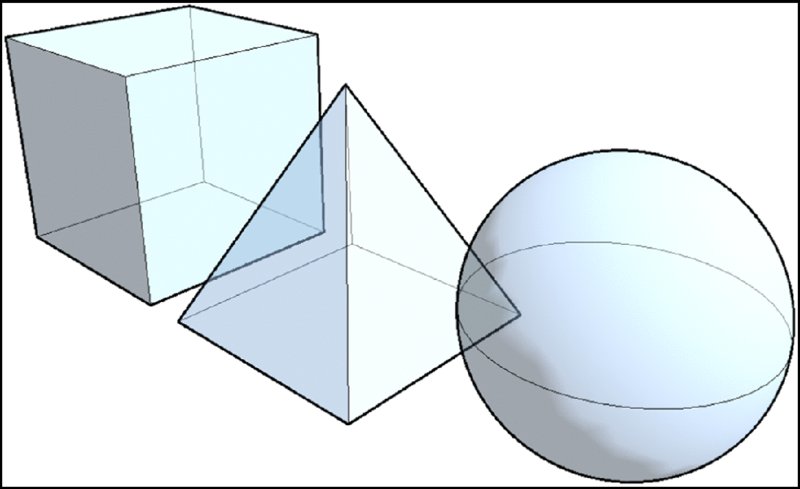
Figure 8.11 Cube, pyramid, and sphere masses
You’ve already started the command with either the Model In-Place or In-Place Mass command. The next step will be to create the 3D geometry inside the family. Mass geometry is created in a two-step process: First, create the 2D shape of the object; then use the Create Form tool to generate the 3D geometry. This process is different from typical modeling software applications because it does not require you to choose a specific modeling command before you begin to explore your design.
Now, let’s get into the details with the following steps:
- For the cube, you’ll first need to sketch a square in a plan view. From the Create tab in the ribbon, in the Draw panel, use the Line or Rectangle tool to sketch a 100' × 100' (30 m × 30 m) square.
- Activate the default 3D view, and then click the Modify button in the ribbon. Select the lines you sketched in the previous step. You may need to press the Tab key to ensure that all four lines of the square are selected. From the contextual tab in the ribbon, choose the Create Form flyout tool from the Form panel, and choose Solid Form. You will see a dimension in the 3D view that indicates the default height of the extrusion. Click the dimension value and then type 100' (30 m) and press Enter on the keyboard to set the desired height.
- In the contextual tab of the ribbon, click Finish Mass.
- Return to the Massing & Site tab in the ribbon, and then click In-Place Mass. Name the next mass Sphere.
-
From the Create panel in the ribbon, select the Circle tool from the Draw panel. In the Options bar, set the Placement Plane to Level : Midpoint. Set the Radius to 50' (15 m).
You may get a warning that the elements are not visible in the current view. That’s fine for now; continue to the next step.
-
In a 3D view, click the Modify button in the ribbon, and then select the circle. From the contextual tab in the ribbon, choose Create Form ➢ Solid Form. This will pop up two visual options for you (Figure 8.12). One will allow you to simply extrude the circle and create a cylinder; the other will allow you to create a sphere. Choose the Sphere option.
- In the contextual tab of the ribbon, click Finish Mass.
- Once again, return to the Massing & Site tab in the ribbon, and then click In-Place Mass. Name the next mass Pyramid. For this shape, you will need to sketch a square in plan and a triangle in elevation before you use the Create Form tool.
-
Activate the Level 1 floor plan and sketch a square that measures 100' × 100' (30 m × 30 m). From the Draw panel in the ribbon, click the Plane tool. Draw two reference planes—one for each centerline of the square you just sketched (Figure 8.13). Select the horizontal reference plane, and in the Properties palette set the Name value to Pyramid Ctr.
- Activate the South elevation view. From the Draw panel in the ribbon, click the Line tool. You will be prompted to select a work plane. Choose the Name option, and from the drop-down list select Reference Plane : Pyramid Ctr. Sketch a triangle as shown in Figure 8.14. Make sure to use intersection and endpoint snapping to make the base of the triangle in line with Level 1 and at the intersection of the Top level and the vertical reference plane.
- In a 3D view, click the Modify button in the ribbon. Select both the square and the triangle, and then select Create From ➢ Solid Form from the contextual tab in the ribbon. The Create Form command will detect that the most likely configuration of these two 2D shapes is to sweep the triangle along the square path, thus forming a pyramid. Click Finish Mass in the contextual tab of the ribbon, and you will see the three masses that you’ve created: cube, pyramid, and sphere (Figure 8.15).
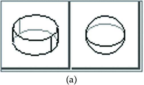
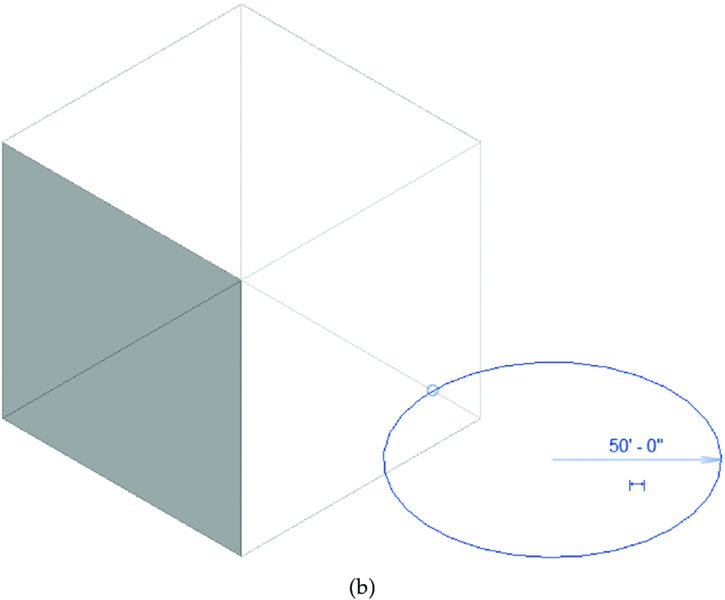
Figure 8.12 Create Form options for a circle
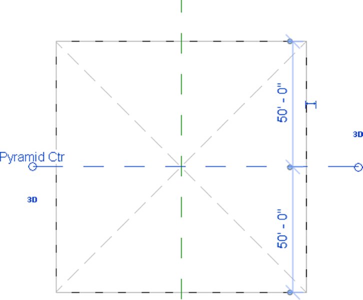
Figure 8.13 Draw two reference planes in the pyramid sketch
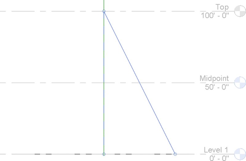
Figure 8.14 Sketch a triangle in elevation.
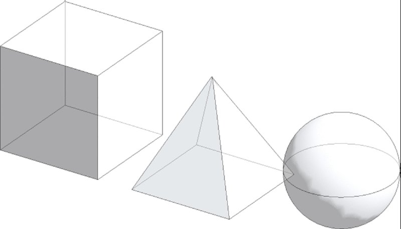
Figure 8.15 Cube, pyramid, and sphere.
As each form was finished, the in-place mass was completed, and the process was repeated for each new mass. In the Project Browser, locate the Families branch and the Mass category. Expand the branch and you will see each mass as a separate item.
Placing a Mass
Continuing with the previous exercise, you will now load and place a mass family. There are many premade families in the default libraries for Revit software. We have already loaded a mass family in the project files for this exercise. Continue with the c08-Massing-1-Start.rvt or c08-Massing-1-Start-Metric.rvt file by following these steps:
- Activate the Level 1 floor plan. Switch to the Massing & Site tab in the ribbon and click Place Mass. In the Type Selector, make sure that either Gable or M_Gable is selected.
- Click an area to the right of the mass forms you created in the previous exercise steps. Click the Modify button in the ribbon and then select the Gable mass you just placed.
- In the Properties palette, set the following values:
- Width: 100' (30 m)
- Depth: 100' (30 m)
- Height: 100' (30 m)
- Eave Height: 50' (15 m)
When you switch back to a 3D view, you will see the Gable mass family in the same context as the in-place masses you created previously (Figure 8.16). All of the mass forms will function similarly as you assign mass floors, place building elements by face, and create schedules. The main difference is that to edit the geometry of the placed mass, you must do so by changing the values in the Properties palette. Keep in mind that you may also load a different mass family and swap one shape for another. You cannot swap an in-place family for a loaded family.
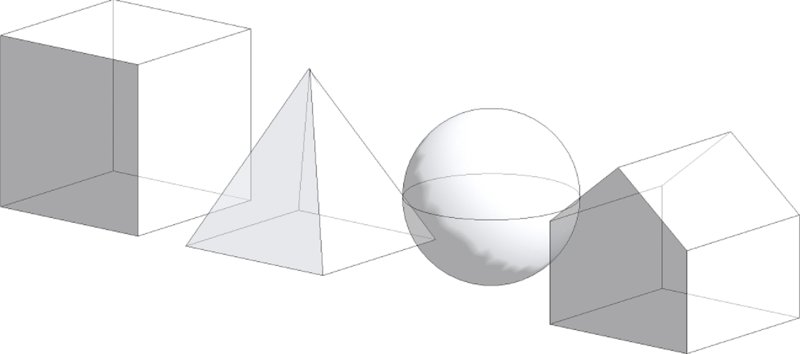
Figure 8.16 The Gable mass family is placed and modified.
 Creating Mass Floors
Once you have created some solid mass forms, it’s important to understand how to create mass floors. The Mass Floors dialog box allows you to generate some quick floor plates and get a rough idea of the floor areas available in your masses. This technique will work equally well with in-place masses or loaded mass families.
To create mass floors, follow these steps:
- Activate the South elevation view. Use the Copy tool from the Modify tab in the ribbon to create more levels in addition to the three provided in the exercise file. Place the copied levels at intervals of 10' (1,500 mm), so you have a total of 10 levels (Figure 8.17).
- In a 3D view, select all the masses and click the Mass Floors button in the contextual tab of the ribbon.
- In the Mass Floors dialog box, check the boxes for all the available levels. This allows you to assign a conceptual floor plate wherever each selected level intersects a mass form. Click OK to close the dialog box.
Figure 8.17 Create multiple intersecting levels
Wherever the selected levels intersect the mass forms, floor faces will be generated, as shown in Figure 8.18. Now the masses and floor faces can be calculated and scheduled. If you select any one of the masses and observe the parameters in the Properties palette, you will see that Gross Floor Area now reports an area that will change depending on how many mass floors are assigned to that mass.
Figure 8.18 Floor area faces assigned to mass forms
Scheduling Masses
With the mass floors created, you can now schedule them and begin to understand what kind of areas you have for floor plates in these shapes. Remember, you can do this exercise with any type of mass shape, and it can be a great way to validate your building’s program against a variety of building forms.
Let’s continue with the exercise by following these steps:
- From the View tab in the ribbon, click Schedules ➢ Schedule/Quantities, and you’ll be given the option to schedule the Mass category itself or various subcategories, including Mass Floor (Figure 8.19). Select Mass, and we’ll schedule the masses so we can do a comparative analysis between the different mass types.
- Select the fields Family, Gross Floor Area, Gross Surface Area, and Gross Volume, as shown in Figure 8.20. Add them to the Scheduled Fields table by clicking the Add button.
For this example, we’ll also show you how to create two calculated values. This will allow you to calculate the overall volume of each mass compared to the floor area, as well as the overall surface area compared to the floor area. Schedules like this will be helpful during the early design process to help you understand how efficient the space of your design is compared to the volume and surface area required to contain that space. Follow these steps:
- Click the Calculated Value button in the Fields tab of the Schedule Properties dialog box, and name the new calculated value Volume to Floor Ratio, as shown in Figure 8.21. In the Formula area, enter the following formula, and be sure to use the correct case: (Gross Volume / 1) / Gross Floor Area. In metric units, the formula is (Gross Volume / 1m) / Gross Floor Area. To keep the units consistent, you divide the gross volume by 1' (1 m) before dividing by the gross floor area. Click OK to accept the formula.
-
To create your next calculated value, click the Calculated Value button again and name this formula Surface to Floor Ratio. In the Formula box, enter the following formula and again be sure to maintain the correct case: Gross Surface Area / Gross Floor Area. Once you’ve entered the formula, click OK (Figure 8.22).
The finished schedule is shown in Figure 8.23. Notice that, proportionally, a sphere and a cube have efficient floor areas compared to their corresponding surface area and volume.
Figure 8.19 Creating a schedule
Figure 8.20 Scheduled fields
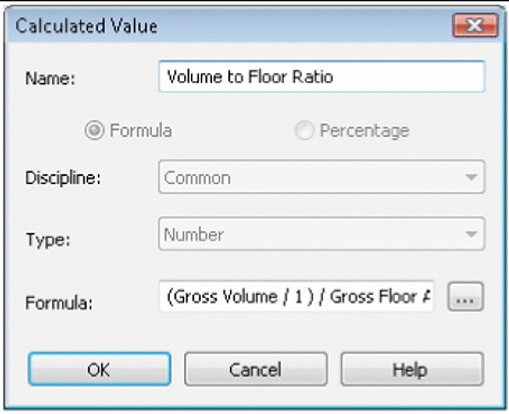
Figure 8.21 Create a calculated value for volume-to-floor ratio.
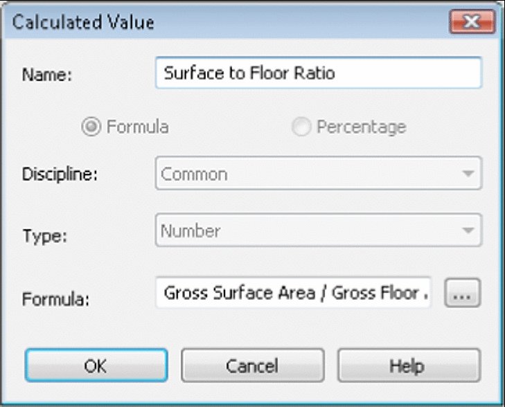
Figure 8.22 Create a calculated value for the surface-to-floor ratio.
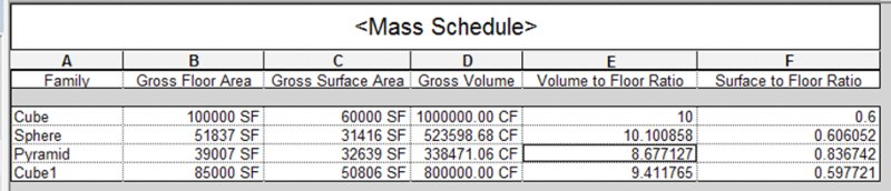
Figure 8.23 Completed schedule
On the other hand, the pyramid mass will require significantly more surface and volume to create the same relative surface area as a cube or a sphere; thus, a pyramid takes far more surface area than a cube to contain the same amount of space.
You can download the finished file from the book’s web page. It’s in the Chapter 8 folder and is named c08-Massing-1-Finished.rvt.
Massing Surfaces
Now that we have discussed how to create or place solid mass forms, let’s review some of the ways in which you can generate massing surfaces. Similar to the process of creating a solid massing form, you can select one or more lines and then use the Create Form tool to generate a surface. Figure 8.24 shows a number of reference line types you can create with the Draw tools: Spline Through Points, Spline, Curve, and Line.
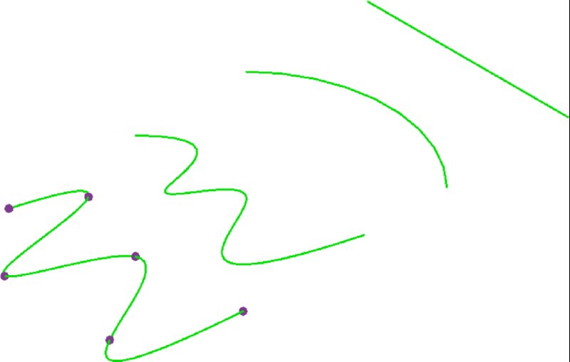
Figure 8.24 Reference line segment types
As you can see in Figure 8.25, each of these reference lines has different control points that allow for further control.
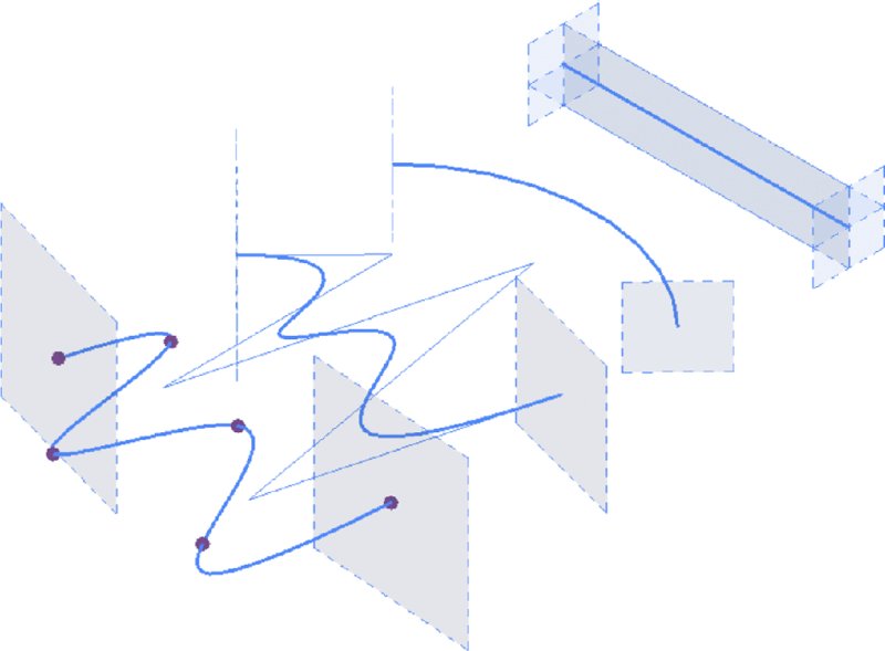
Figure 8.25 Reference line control points
Because these are not closed loops, the form that will generate from each of these segments will only be a surface (Figure 8.26). You generate the form by selecting each of the lines (one at a time, not together) and then selecting Create Form ➢ Solid Form.
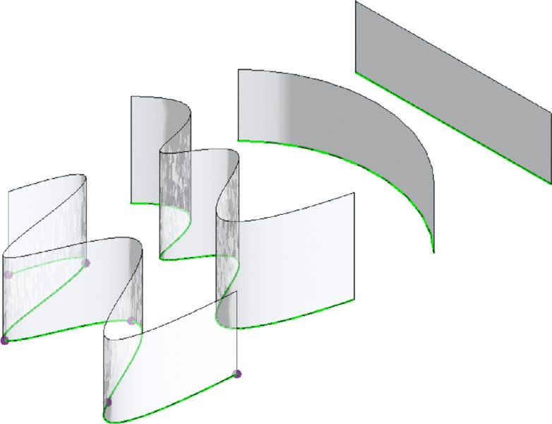
Figure 8.26 Surface forms
You can also create surface-based forms from more than one line at a time. The result is a surface that can be controlled in more complex ways than a single line.
Take the Spline Through Points line, for example. The form on the left in Figure 8.27 creates a face that is controlled by a single reference line, whereas the form on the right is a face controlled by two (and it could be more) reference lines.
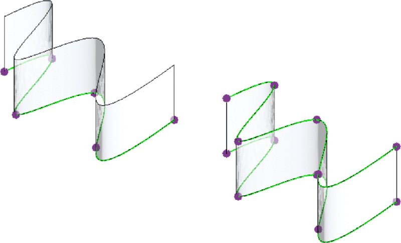
Figure 8.27 Surfaces based on multiple splines
Moving the location of the control points on the form on the left maintains a consistent height to the top of the surface previously generated, whereas moving the control points of the surface on the right creates a surface that varies in height (Figure 8.28).
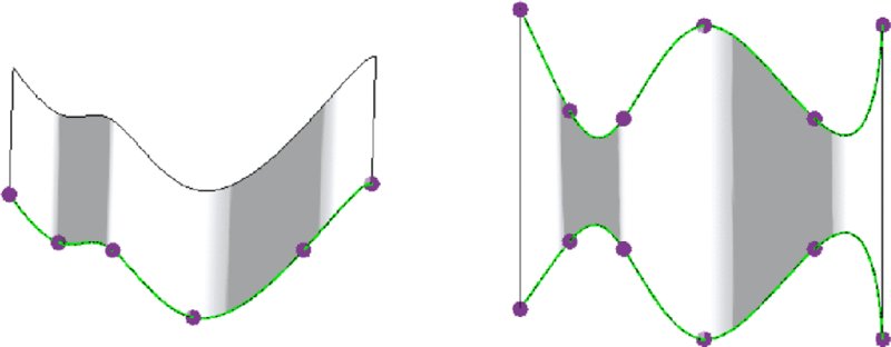
Figure 8.28 Single and multi-spline surfaces
After a surface is generated, it’s also possible to add more profiles, as illustrated by Figure 8.29. A profile is basically a joint in the form, allowing for another control location. Any profile you add will respond in the same way the edges of the mass respond, by allowing you to modify and manipulate both them and their location. We’ll demonstrate how to use this tool and the rest of the Form Element panel later in the chapter. For now, we’ll step through some of the tools so you can get an understanding of the relationship of tool to form and see how quickly you can create forms.
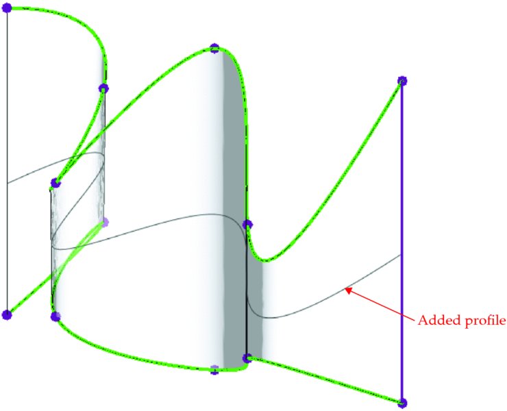
Figure 8.29 Adding a profile
After the profile was added, it was moved to create a bulge in the surface (far right shown in Figure 8.30).
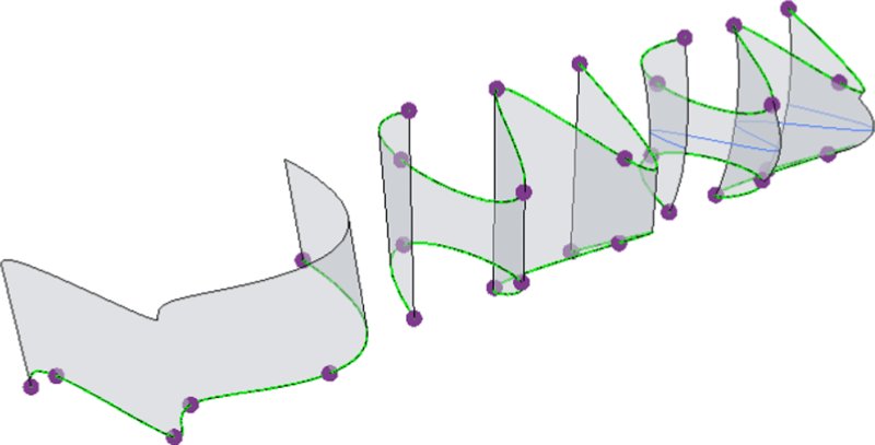
Figure 8.30 Moved profile
The fourth iteration of the form was created by selecting the surface and then choosing the Dissolve tool in the contextual tab of the ribbon. This removed the surface but left us with all the references used to create the form.
Once the face was dissolved, another reference called Spline Through Points was added between the upper and lower reference splines. The result is shown in Figure 8.31.
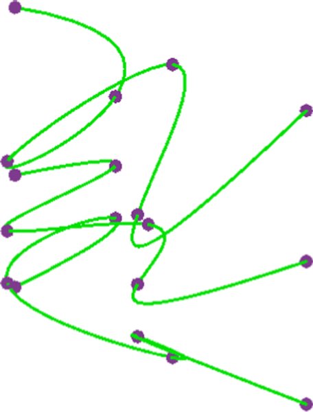
Figure 8.31 Additional spline added
Selecting all three references and then choosing the Create Form tool stitched them all into a new single-surface form (Figure 8.32).
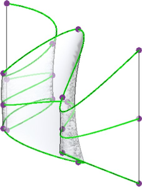
Figure 8.32 New surface form
Selecting the points within the middle reference allowed for even more complex surface control (Figure 8.33).
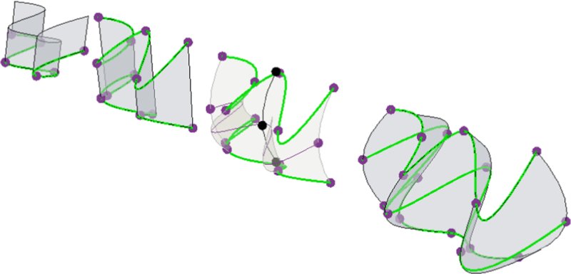
Figure 8.33 Edited center spline
Keep in mind that selecting lines or shapes to create forms is a sequential operation (when it’s not in a closed loop). Window-selecting all the splines and then creating the surface will result in very different forms than if you were to sequentially select adjacent splines (Figure 8.34). The result is that the surface form isn’t interpolated as smooth between the upper and lower splines. Instead, a distinct edge is created between the two splines.

Figure 8.34 Spline-based surfaces
As you can see, it’s easy to create complex surface forms using reference lines. Now let’s begin to create complex forms using reference planes.
Using Free-form Building Massing
Now that you are familiar with the basic functionality of the massing tools, let’s learn how to generate and explore building forms in an informal way. The exercise in this section will build on the skills you learned in the previous section, and you will learn how to directly manipulate solid geometry using grips, gizmos, and dimensions.
Start by downloading and opening either c08-Massing-2-Start.rvt or c08-Massing-2-Start-Metric.rvt from the book’s web page. Begin the exercise by following these steps:
- Activate the Level 1 floor plan. From the Massing & Site tab in the ribbon, click In-Place Mass and name the new family Mass 1.
- From the Draw panel in the ribbon, choose the Rectangle tool. In the Options bar, check the box to make a surface from closed loops. Sketch a rectangle that is approximately 40' × 90' (12 m × 28 m). Specific dimensions are not important; it’s more about the proportions.
-
Open the Default 3D view, and click the Modify button in the ribbon. Hover the mouse pointer over one of the lines in the rectangle sketch. Press the Tab key until you see Form: Form Element displayed in the status bar. Select the form element and you will see controls that allow you to pull the surface into a solid (Figure 8.35). Using the control pointing in the up direction, press and drag it until the form is about 140' (43 m) tall.
There are a number of shape handles that allow you to modify each face, edge, and intersection. Simply hovering over each face, edge, and vertex will highlight the appropriate control. You can also press the Tab key on the keyboard to select the desired control. We’ll step through some of the selections to give you an idea of what the controls for the faces, sides, and points look like.
- Starting with any vertical face, select it and you’ll be given the control shown in Figure 8.36.
- Select an edge and you will have the ability to move the edge of a form in multiple directions (Figure 8.37).
-
Select the point at the intersection of several edges. You will likely need to press the Tab key to select a corner point. This control allows you to modify the location of a vertex (Figure 8.38).
The control arrow allows you to modify the selected element parallel to the direction of the arrow, whereas the angled indicators of the same colors as their corresponding arrows allow you to modify the location of the selected element perpendicular to the arrow.
There are also some tools to help you with the visualizations of the mass, especially as it gets more complex. One of these is the X-Ray tool, which will take a solid and turn it into a semitransparent form. Turn on X-Ray mode by selecting the form and clicking the X-Ray button on the Form Element panel. This will let you see any of the profiles and controls on the other side of the object.
Now that X-Ray mode has been enabled, look at the options that are provided for turning a rather simple, extruded form into something complex. An edge may be added to an existing form from vertex to vertex or parallel with the trajectory of the form (shown as a dotted line from the upper to the lower face).
- Click the Modify button in the ribbon, and then select the front face of the extruded mass you previously created. From the contextual tab in the ribbon, select Add Edge. As you mouse over the face you’ve selected, you’ll be given a ghosted line to locate the edge. Simply click to place it, as shown in Figure 8.39.
-
 Once the edge has been added, you can push or pull the face adjacent to the new edge, as shown in Figure 8.40. Click the Modify button, and then select the face to the left of the edge you created in the previous step. Press and drag the green control arrow to move the face back into the extruded form.
 - Select the overall mass form again, and then click the Add Profile tool on the Form Element panel in the ribbon. You’ll get the same ghosted line as you did to create the edge, but this time it will be the circumference of your element—essentially representing the profile at that point. Click to place it as shown in Figure 8.41.
- Again, click the Modify button in the ribbon, and then select the edge at the upper-left of the extruded form. Use the green control arrow to pull the edge away from the mass form. Pushing or pulling a point or single edge will create curved and warped surfaces (Figure 8.42). This is fine because the form that you’re creating can be rationalized later when you are adding a pattern to the surface.
- Click the Add Edge button in the contextual tab of the ribbon, and then click the vertices indicated in Figure 8.43 in the order they are numbered. Doing so will force the warped faces to become triangulated and planar, because three points define a plane.
- Select the edge at the upper-right of the mass form and use the red control arrow to pull it away from the form, as shown in Figure 8.44. Again, it’s not necessary to maintain the exact dimensions of what you see here; it’s about trying to keep the proportions appropriate. This is what free-form massing is all about!
Figure 8.35 Creating a solid form
Figure 8.36 Face control
Figure 8.37 Edge control
Figure 8.38 Vertex control
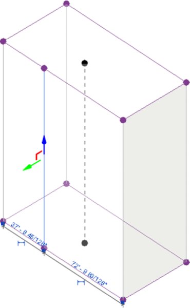
Figure 8.39 Adding an edge to a form
Figure 8.40 Pushing the face
Figure 8.41 Adding a profile to the form
Figure 8.42 Pulling the edge to create a warped surface
Figure 8.43 Adding more edges to eliminate warped surfaces
Figure 8.44 Pulling the upper edge
Dissolving and Rebuilding
Now, let’s say you have come to a point in your design exploration when you would like to simplify the mass form you’ve created and start exploring some other alternatives. The tool to perform this function is called Dissolve. Using the Dissolve function will remove the mass solid and leave behind the profiles that define the solid. The dot in the center of each plane is a control that will allow you to edit the elevation, rotation, and location of each profile.
 Continue with the
 c08-Massing-2-Start.rvt or c08-Massing-2-Start-Metric.rvt file you used for the previous exercise, and follow these steps:
- In a 3D view, select the entire form and then click Dissolve on the Form Element panel in the ribbon. Only the profiles will remain, as shown in Figure 8.45.
-
Select all the remaining profiles and then click Create Form ➢ Solid Form. This will stitch the form back together in a way that interpolates the shape as more of a lofted blend (Figure 8.46). Once the new shape is created, you can add more profiles or edit the shape using the tools we just reviewed.
There are a few other ways to generate shapes using the profiles you just created. For instance, if you select only two profiles at a time, then you’ll get a form like the one in Figure 8.47. This form was created by first selecting the bottom and middle profiles and then creating the form. Then the middle and upper profiles were selected and another form was created. The result is straight—rather than curved—interpolation between the profiles.
As another way to generate form using these profiles, you can alter the shape of the profiles before you create the form again. In the next steps, you will delete the straight edges along one side of the profiles and then define a curved edge.
-
Start by deleting the existing edges along the right side (you’ll have to tab to select just the edges), as shown in Figure 8.48.
Now you’ll want to draw a fillet arc to rejoin the two remaining edges. Before you can draw the arc, you first have to define the right work plane.
- Click the Set command from the Work Plane panel. Highlight the control point in the center of the profile, and press the Tab key to cycle through your options until you get a work plane that is parallel to your profile (Figure 8.49). Click to select. Now you’ll be able to draw your arc on the proper plane.
- From the Draw panel in the ribbon, choose the Fillet Arc tool. Click each edge on either side of the open end, and then click again to set the arc in place. Once the work plane is selected, you’ll be able to draw additional model lines. In this example, you’re using a fillet arc to connect the lines. You’ll do the same thing for the other two shapes.
- Repeat steps 4 and 5 for the other two profiles.
- Select the lower two profiles and click Create Form ➢ Solid Form. Then do the same with the upper two profiles. Finally, you’ll want to remove any blends by adding an edge to the opposing edges.

Figure 8.45 Using Dissolve to remove the mass solid
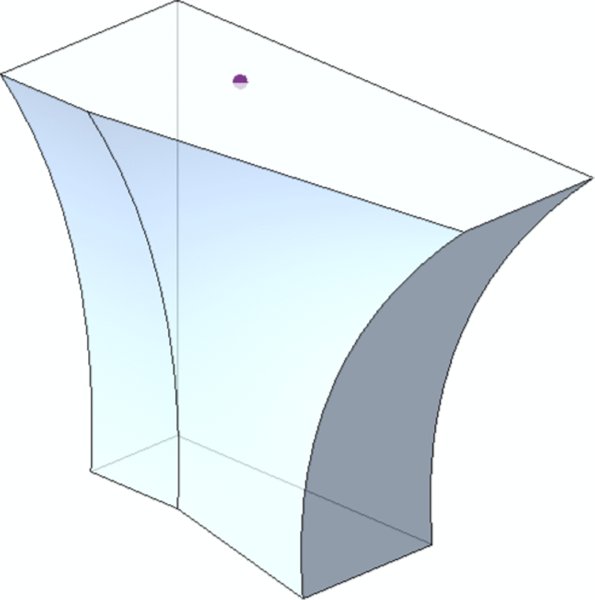
Figure 8.46 Making a lofted blend from three profiles
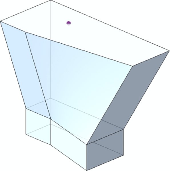
Figure 8.47 Making a blend from two profiles at a time
Figure 8.48 Deleting the right edge to modify the profile
Figure 8.49 Selecting the work plane
Creating additional mass solids is easy. You can select an existing face, as shown in Figure8.50, and then select the Create Form command.
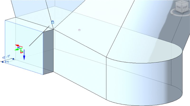
Figure 8.50 Creating additional mass forms
The same tools were used to create the form shown in Figure 8.51. Click the Finish Mass command in the contextual tab of the ribbon and return to the regular project environment.
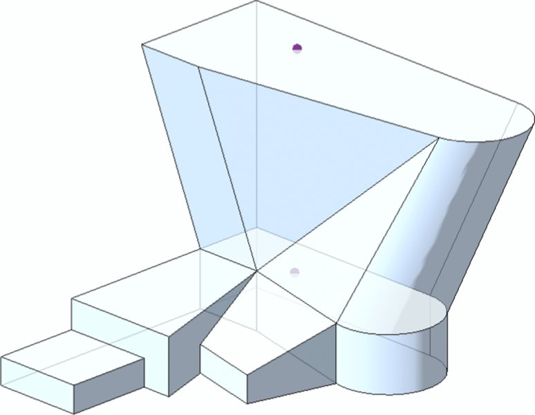
Figure 8.51 Creating another form
Once you’re out of In-Place Massing mode, you’ll notice that if you select the model, many shape handles simultaneously appear in the form of solid blue arrowheads (Figure 8.52). You can use shape handles to push and pull your solid mass, but you won’t be able to modify edges or vertices without reentering In-Place Massing mode.
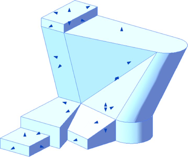
Figure 8.52 Using shape handles
Figure 8.53 shows the finished mass in a perspective view. Both solids and voids can be used to complete a mass form. Whereas solids will add more geometry, voids will remove geometry from your mass.
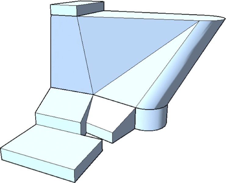
Figure 8.53 The finished form
To demonstrate this, we’ll return to In-Place Massing mode and create another face on the top of the existing form (Figure 8.54).
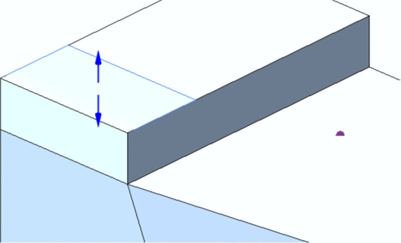
Figure 8.54 Adding a void
STARTING VOIDS AS SOLIDS
If you create the void as a void, it will immediately cut the solid mass and become invisible. This can be annoying when you’re trying to resolve your design and want to selectively cut after you’ve intuitively resolved a design idea. Fortunately, there’s another way to create the form as a void.
Follow these steps:
- Rather than creating a void, start by creating a solid of a different color and category to keep things clear during your design iteration. You can simply give the new solid a different material type to change the color.
- Select the solid mass and convert it to a void by changing the Solid/Void property in the Properties palette, as shown in Figure 8.55.
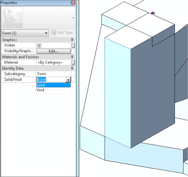
Figure 8.55 Converting a solid to a void
Figure 8.56 shows the result of the void cutting the solid. Note how the form on the left side of the image has changed from Figure 8.53. Keep in mind that if you want to convert the void back to a solid, you’ll have to uncut any geometry that was being cut by the void. But the nice thing about this technique (converting solids to voids and then cutting) is that you’ve selectively cut only the solids that you wanted to cut. Had you originally modeled the void as a void, you would have found that the void was cutting many solids and you’d have had to uncut solids that weren’t even overlapping with the void!
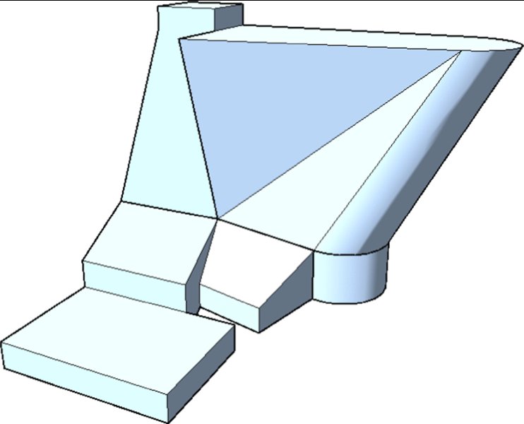
Figure 8.56 Cutting the void
Overall, creating solid masses intuitively is a great way to establish, analyze, and visualize your overall design idea. As you saw previously in the chapter, mass floors allow you to even quantify gross floor areas before you’ve committed to geometry.
Furthermore, it’s possible to put different intuitive massing ideas inside different design options (covered in Chapter 10, “Working with Phasing, Groups, and Design Options”) so that many ideas can live in a single Revit project file. Simply initiate worksharing and create worksets for each study mass. Multiple team members will be able to see one another’s work at the same time and in context with their design ideas. This is the holistic kind of team approach to design information that makes massing a unique and valuable design tool. If you’d like to investigate this file further, you can download the file c08-Massing-2-Finished.rvt from the Chapter 8 folder of the book’s web page.
Next, we’ll investigate parametric and formulaic solid mass creation in the Family Editor.
Creating Formula-driven Massing
Formula-driven massing can be done in the project environment, but the challenge is that you have to work in the context of the project, and all the parameters, formulas, reference planes, and lines can start to get in the way. Therefore, having the option of creating form-driven masses in the Family Editor without the clutter of the project environment can help you focus on what you’re trying to accomplish.
In this section of the chapter, we will show you two different methods for creating formula-driven massing. First, you will create a generic model family and then load it into the project environment as part of an in-place mass. Second, you will create a conceptual mass family to observe the differences in modeling tools and how they will affect your design explorations.
Creating a Generic Model Mass Family
Although it’s possible to create complex forms as a generic model in the Family Editor, they do not behave as masses when you place them in the project. You can assign standard walls, curtain walls, and roofs to the faces, but you can’t add patterns, create mass floors, or even schedule the results as a mass. The tools you will use in this exercise are the tools available for building most other 3D content using extrusions, sweeps, and blends. It’s good to understand how to use these tools so you’re familiar with all the types of modeling in Revit software.
-
Open a Generic Model template by choosing the Application button ➢ New ➢ Family. Select either
Generic Model.rftorMetric Generic Model.rftfrom the list of default templates.In some cases, you can change the category of a family by clicking the Family Category and Parameters button in the ribbon; however, you can’t convert a generic model family to a mass (Figure 8.57). You’ll need to maintain the family as a Generic Model and then place it into an in-place mass within a project.
- Go to a floor plan reference-level view in your family. From the Create tab in the ribbon, click the Reference Line tool (not Reference Plane). Draw a reference line along the y-axis (up), as shown in Figure 8.58. Note that the reference line is drawn from the intersection of the reference planes. Note also that we have increased the line weight of Reference Lines in the Object Styles settings for clarity.
-
Draw another reference line in a downward direction along the y-axis (Figure 8.59). These reference lines will control the angular “twist” in your finished family.
Now you’re going to create a blend that will be associated with the reference lines you just created. The bottom of the blend will be associated with the first reference line, and the top of the blend will be associated with the second reference line.
- From the Create tab in the ribbon, click the Blend tool. By default, you will start by defining the bottom profile of the blend. Click the Set command in the Work Plane panel of the contextual tab in the ribbon. Choose the Pick A Plane option (Figure 8.60), click OK, and then click the first reference line you drew.
- From the Draw panel in the contextual tab of the ribbon, choose the Rectangle command and sketch a 20' (6 m) square in the plan view.
- Switch to the Annotate tab in the ribbon and click the Aligned dimension tool. Place a dimension on both vertical lines in the square sketch and the vertical reference line—not the reference plane. Click an empty area of the plan view to finish the dimension command. Highlight the finished dimension and click the EQ icon on the dimension string. The plan view should look like the image in Figure 8.61.
- Use the Aligned dimension tool again to create dimensions for the vertical and horizontal sketch lines. This time, you’ll want to select the Reference Plane as your center dimension. The goal is to make the box equal on all sides and equidistant from the reference planes (Figure 8.62). After you place the two dimensions, select them, and from the Options bar go to the Label drop-down list, and then choose <Add Parameter>. In the Parameter Properties dialog box, set the following values:
- Name: BW
- Type or Instance: Instance

- Edit Tooltip: Bottom width of blend
The plan view should now look similar to the image in Figure 8.62. You can adjust the value of the BW parameter by clicking the Family Types icon from the Properties panel in the ribbon.
- From the contextual tab in the ribbon, choose Edit Top. Click the Set command in the Work Plane panel, choose the Pick A Plane option, click OK, and then click the second (downward) reference line you drew in step 3.
- Repeat steps 5 and 6 for the top sketch. Equally distribute the overall dimensions in relation to the downward reference line and create the parameters as you did previously, but name the parameter TW (Top Width), as shown in Figure 8.63.
- In the Properties palette, locate the property named Second End. Click the small button at the right end of the row—this is the Associate Family Parameter button. Click the Add Parameter button. In the Parameter Properties dialog box, set the following values:
- Name: H
- Type or Instance: Instance
- Edit Tooltip: Height of blend
- Click OK to create the parameter and close the open dialog boxes. Now select Finish Family (the green check mark) from the contextual tab in the ribbon to complete the blended form.
- You should take a moment to test that the reference lines control the top and bottom sketches of the blend. Activate the default 3D view, select the reference line to highlight it, and then move the end of the reference line. Be careful when moving the reference line. The goal is to test the parameters, so when you move the line, do so by dragging the line slightly. You’ll see the resulting forms change. Don’t use the Move command—it will break the parameters. The other end remains associated with the intersection of the default reference planes, and the top and bottom sketches rotate, as shown in Figure 8.64.
- From a plan view, move the reference lines so that they’re no longer on top of the reference planes. From the Annotate tab, click the Angular dimension tool and place dimensions between each reference line and the vertical reference plane.
- Select the upper angular dimension, and from the Label drop-down list in the Options bar choose <Add Parameter>. Create a new family parameter with the following values:
- Name: BA
- Type or Instance: Instance
-
Edit Tooltip: Bottom angle, counterclockwise from 90
Furthermore, you can add parameters to control the top and bottom angles of the blend. We’ve called these instance parameters BA and TA (for bottom angle and top angle, respectively).
- Select the lower angular dimension and again choose <Add Parameter> from the Label drop-down list. Create another new parameter with the following values:
- Name: TA
- Type or Instance: Instance
-
Edit Tooltip: Top angle, clockwise from 270
Figure 8.65 also shows all the parameters that control this blend. From the Create tab in the ribbon, click the Family Types icon. Go ahead and test the parameter values by changing angles in the Properties palette and clicking the Apply button (or moving your mouse out of the palette). The form should rotate and twist. This is how you will interact with the form after you load it into a project environment.

-
You’re going to use the edges of this blend to drive the geometry that you’re going to create, but since you don’t want to see this blend, turn it into a void. With the blend selected, use the Solid/Void drop-down list in the Properties palette (Figure 8.66). The blend form will change color to a yellow-orange if you set your visual style of the view to Shaded.
- From the Create tab in the ribbon, click the Sweep tool. Select Pick Path (not Sketch Path) in the contextual tab of the ribbon to select the edges of the blend previously created. Pick the edges of the blend, as shown in Figure 8.67. Note the location of the sketch plane along the lower rear edge. This is because it is the first edge selected.
- Once you select the edges of the blend, click the green check mark to finish the path. Click the Select Profile icon and select Edit Profile from the contextual tab in the ribbon. Doing so allows you to sketch the profile in direct context of the selected edges.
- Sketch a profile 5'-6" (1.7 m) wide × 4'-6" (1.4 m) high. After you sketch the profile, add aligned dimensions, and then add parameters to the profile width and height as you’ve done previously in this exercise. We’ve called the instance parameters PW (profile width) and PH (profile height), respectively (Figure 8.68).
- Finish the sketch and the sweep, and the profile will generate as shown in Figure 8.69.
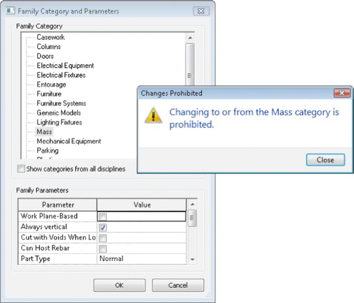
Figure 8.57 Message box explaining you can’t change the category to Mass
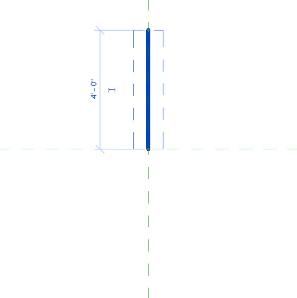
Figure 8.58 First reference line
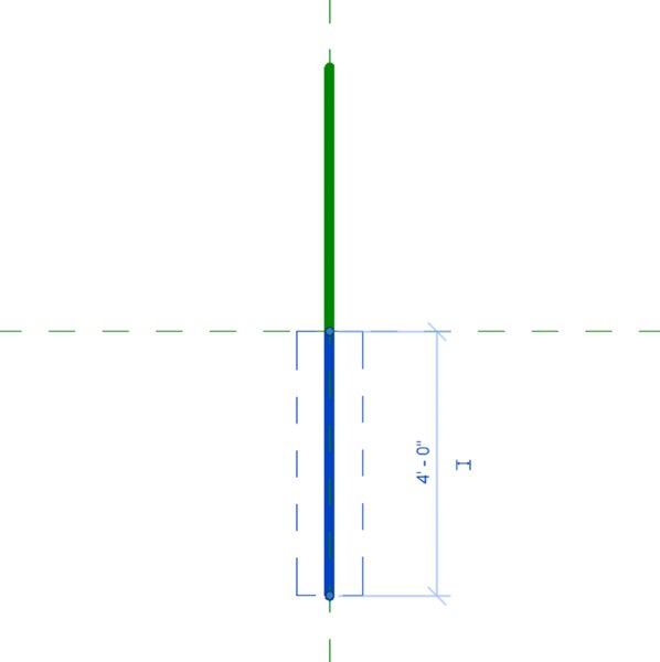
Figure 8.59 Second reference line
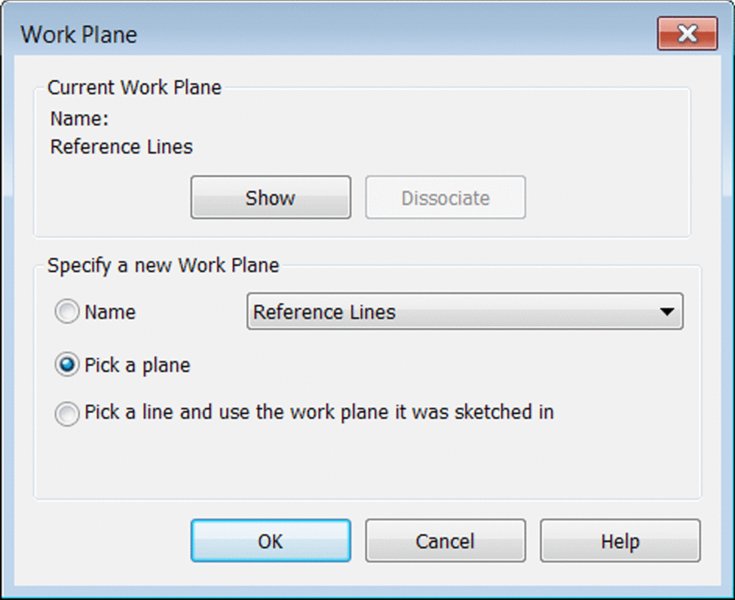
Figure 8.60 Setting the work plane
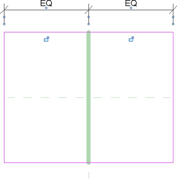
Figure 8.61 Establish equality dimensions.
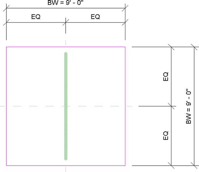
Figure 8.62 Parameter dimensions added to the bottom sketch
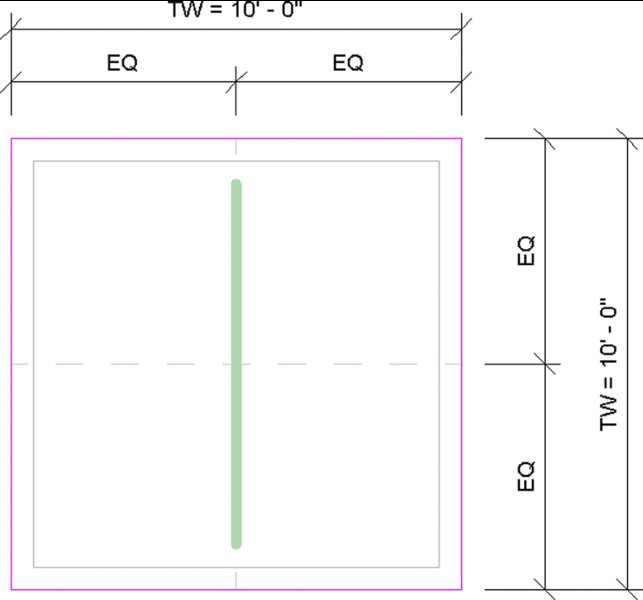
Figure 8.63 Top width parameters and sketch
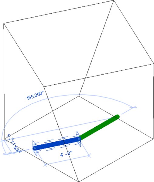
Figure 8.64 Twisting the blend with reference lines
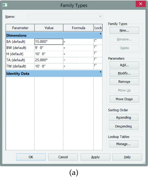
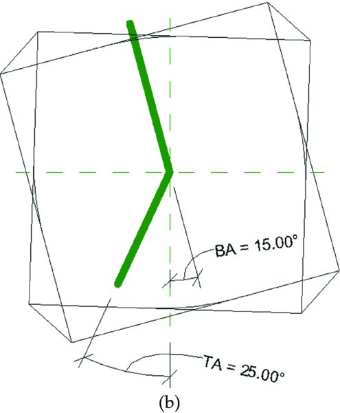
Figure 8.65 Test the dimensional parameters before continuing.
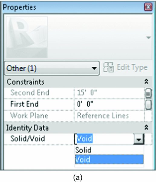
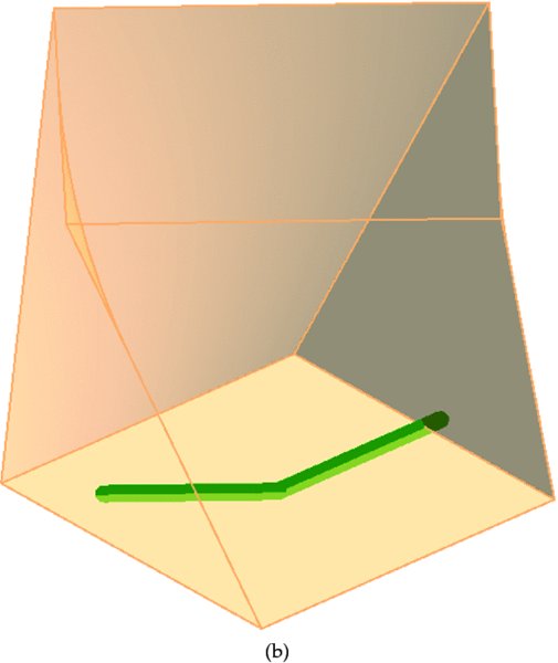
Figure 8.66 Turning a solid into a void
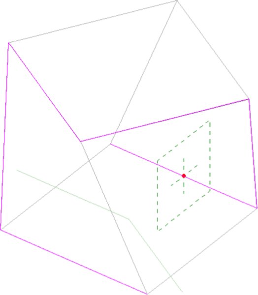
Figure 8.67 Selecting the edges of the blend
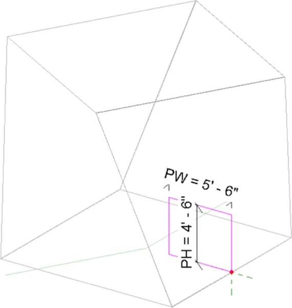
Figure 8.68 Adding parameters to the profile width and height
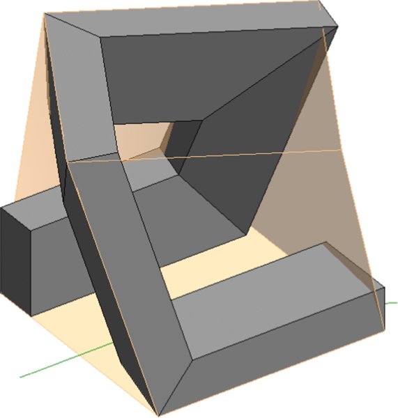
Figure 8.69 The finished sweep
Save the family on your computer as Generic Model Mass.rfa. With the form created, it’s now possible to load this family into your project environment and place it within an in-place mass. To do this, follow these steps:
- Open a new project using the default Architecture template, and begin by creating an in-place mass from the Conceptual Mass panel of the Massing & Site tab. Name the mass Generic Mass.
- While still in the In-Place Mass Sketch mode, toggle back to the mass family you just created and click Load Into Project from the ribbon. You should immediately be ready to place an instance of the loaded family, but if not, switch to the Create tab in the ribbon and click Component. Place the generic family as a component into your in-place mass.
- Select the component you just inserted, and notice in the Properties palette that all the attributes you gave to the mass are available for you to edit. Using these parameters, set the values as follows:
- BW: 160' (49 m)
- TW: 140' (43 m)
- H: 160' (49 m)
- PW: 40' (12 m)
- PH: 65' (20 m)
- BA: 22°
- TA: 22°

- Now finish the in-place mass by clicking the green check mark, which is the Finish Mass button. Even though this is a generic model family, because you’ve placed it during In-Place Mass mode, the software treats it as a mass.
-
Activate the South elevation view and add 15 additional levels. Space the levels every 10' (3 m) apart, as shown in Figure 8.70, so that there are levels that extend across the entire elevation of your massing.
- Select the mass and click the Mass Floors button on the contextual tab in the ribbon. Select and check the boxes for all the levels, and then click OK to apply the changes and close the dialog box.
- Select the mass, and on the contextual tab in the ribbon click Edit In-Place. Hover over one of the surfaces on the generic model, press the Tab key until the status bar indicates a face, and then click to select it. In the contextual tab of the ribbon, click Divide Surface. With the face still selected, go to the Type Selector and choose Triangle (Flat). You’ll also be able to associate patterns and pattern-based components with your generic massing family (Figure 8.71). Continue to do this for each vertical surface on the generic model, and then click Finish Mass.
- Finally, switch to the Architecture tab in the ribbon and click Roof ➢ Roof By Face. Click the horizontal surfaces of the mass and then click Create Roof in the contextual tab of the ribbon. Click the Modify button to complete the command.
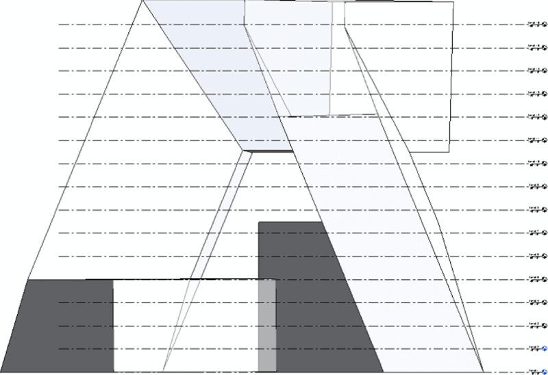
Figure 8.70 Adding levels that extend across the elevation of your massing
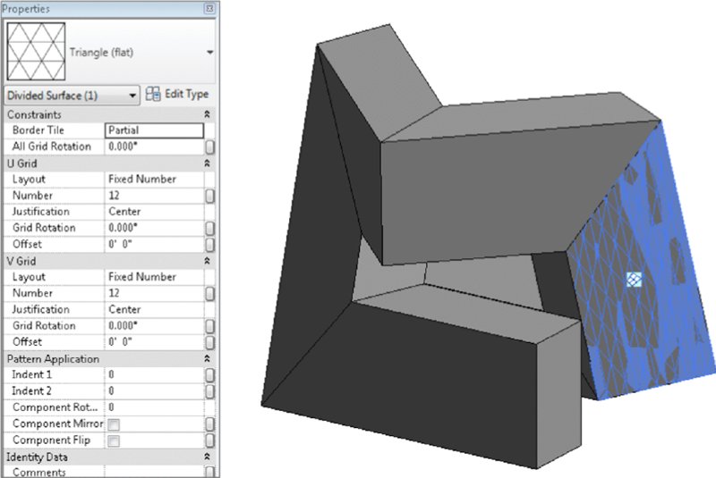
Figure 8.71 Adding pattern-based components
Figure 8.72 shows four perspective views of the completed massing study, all created with the familiar geometry toolset.
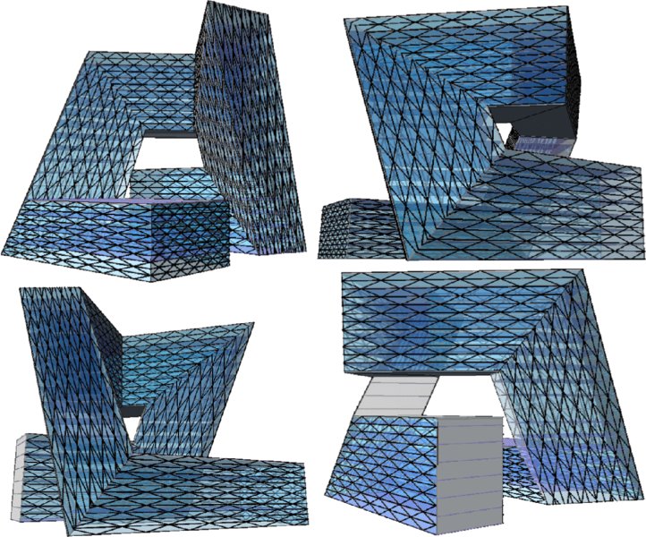
Figure 8.72 Perspective views
We’ve also rendered the model, as shown in Figure 8.73. The results are quite interesting, and you’ll still have the ability to modify the underlying parametric family and then rehost the faces. You’ll also be able to schedule the volume, surface, and floor area of the mass.
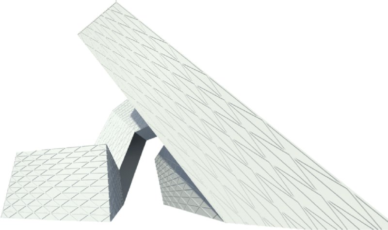
Figure 8.73 Rendering of the generic massing project
You can download and further investigate the files that were used to create this exercise in the Chapter 8 folder of the book’s web page. Download the project file c08_Parametric_Generic_Massing_Finish.rvt, which contains the in-place massing and the loaded generic element.
Now let’s begin to investigate how to create parametric massing in the Family Editor using the conventional massing tools.
Creating a Complex Mass Family
In the previous exercise, we used the basic modeling tools that are available for most family categories. The tools available in the conceptual massing environment are somewhat different. In the next exercise, you will open a conceptual mass family that we have started with a number of datum objects and embedded formulas.
Overall, the UI is not too dissimilar from the project environment. It’s as if you’re creating masses in-place—except that you’re not in the project environment; you’re in the Family Editor. One significant difference that you can see is that there is a single level and two reference planes, which also define the origin for a massing family (Figure 8.74). Keep in mind that when you reload this family into your project, it will update relative to the origin in the family.
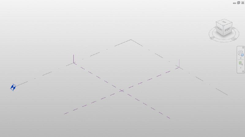
Figure 8.74 The Massing user interface
In the past, the ability to parametrically control objects in the massing editor was done using reference planes and reference lines. The Revit development team introduced reference point elements in 2010, which add another level of control to model elements. Point elements allow for Cartesian X, Y, Z, as well as rotational control.
With all complex and parametrically controlled families, we think it’s best to understand complex families to get the basic rules down first. In this case, the rules are the parameters and formulas that will control a twisting, tapering tower.
To begin this exercise, download and open the file c08-Formula-Massing-Start.rfa or c08-Formula-Massing-Start-Metric.rfa from the book’s web page. Open the Family Types dialog box and observe the parameters and formulas that are included with the exercise file, as shown in Figure 8.75.
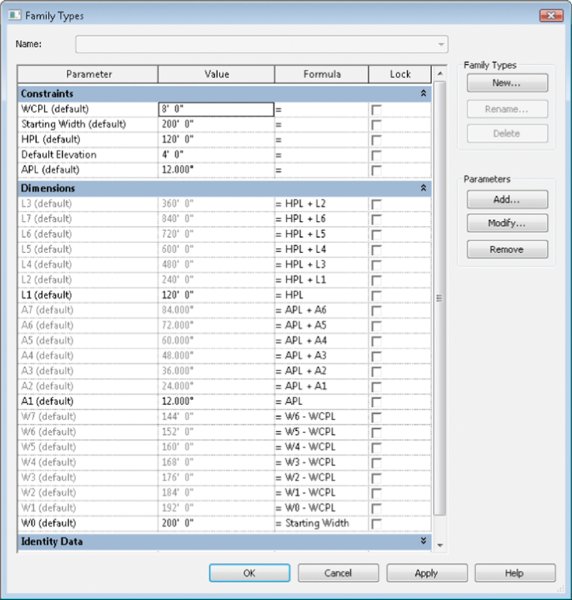
Figure 8.75 The Family Types dialog box
We will briefly describe how this conceptual mass family was created so you can get an overview of the process and employ similar techniques on your own designs. Similar to the steps you performed in the previous exercise, reference lines were used to generate a square sketch at the first reference level.
The reference lines were dimensioned with equality constraints based on the reference planes defining the origin. Overall dimensions were placed and associated with the W0 parameter (Figure 8.76). W0 is shorthand for the width dimension on the 0-level.
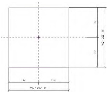
Figure 8.76 Dimensioned reference lines
While in the same view, seven reference points were placed at the intersection of the default reference planes. Each reference point was then elevated manually by dragging the up arrow to move it away from the other overlapping point elements (Figure 8.77).
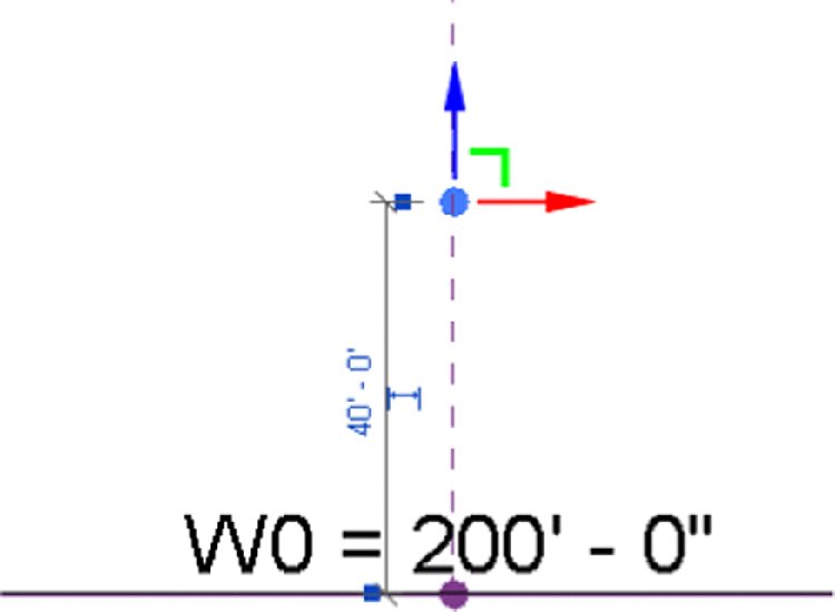
Figure 8.77 Moving the point element
When you select a reference point, you have the option to associate any of the point’s properties with any of the family parameters developed for this conceptual mass. This is done by clicking the small button in the Properties palette next to each property value. For each reference point in this exercise file, the Offset property was associated with a corresponding L-parameter (Figure 8.78). The L-parameters refer to the level number of each of your point elements. The first point element is associated with the parameter named L1 because it is reference Level 1. The second point is associated with L2, and so on. When you associate a property with a family parameter, you’ll notice that the button fills with a small equal sign.
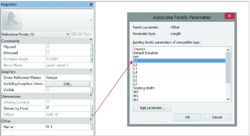
Figure 8.78 Adding a parameter to the point element
By default, the reference point elements are just spherical nodes. Their reference planes are not visible. To make them a little more usable for your modeling purposes, you can set them to display their internal reference planes. With a reference point selected, in the Properties palette you will find a property called Show Reference; set it to Always, and the reference planes of the point elements will be visible (Figure 8.79).
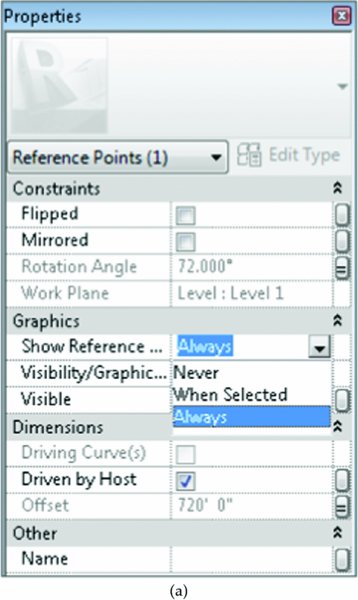
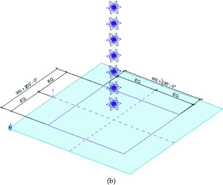
Figure 8.79 Selecting Always next to Show Reference
Next, the Rotation Angle property of each reference point was associated with the corresponding family parameter. Point 1 was associated with A1 (angle 1), Point 2 with A2, and so on.
We then used the Set command in the Work Plane panel to use each point’s horizontal plane as the working reference to draw a square sketch of reference lines associated with each point. Each sketch was dimensioned in a similar way to the first sketch. The dimensions for the sketch associated with Point 1 are W1, the Point 2 sketch dimensions are W2, and so on (Figure 8.80).
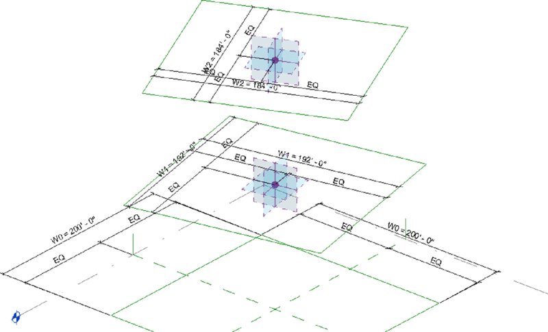
Figure 8.80 Reference line sketches and dimensions
For clarity, we’ve hidden the dimensions in the default 3D view so that you can see all the reference lines and point elements. If you’d like to see all the dimensions configured in this exercise file, activate the 3D view named 3D with Dimensions.
Now let’s begin to create some mass forms using the parametrically driven framework of reference lines in this exercise file. Follow these steps to get started:

- While pressing the Ctrl key, select all the square reference line sketches, and then click Create Form ➢ Solid Form on the Form panel in the ribbon. Although this will look like a simple extrusion, it’s actually a blend with many profiles.
- Open the Family Types dialog box and begin to test the results before loading the family into the project (Figure 8.81). Set the WCPL and APL parameters to 0 and click Apply.
- Test the parameter that controls the distance between levels by increasing the HPL instance parameter (which stands for height per level). If you hover the mouse pointer over these parameters, a tooltip will appear telling you what they mean.
- Now test the ability of the shape to taper (Figure 8.82). Do so by increasing the WCPL instance parameter (which stands for width control per level).
- Next, test the parameters that control the amount of angular twist per level (Figure 8.83). Do so by increasing the APL parameter (which stands for angle per level).
- Start a new project using the default Architectural template. Switch back to the mass family, and click Load Into Project from the ribbon. Place an instance of the conceptual mass family in the project environment. When you select the massing family, you’ll be given access to all of its parameters in the Properties dialog box. You can quickly and easily test the massing parameters to significantly increase the height, width, taper, and incremental rotation of the massing family.
- Switch back to the family file. Hover the mouse pointer near the edge of any face on the mass, press the Tab key until you highlight a surface, and then click to select a surface. Click Divide Surface in the contextual tab of the ribbon. From the Type Selector, choose Rhomboid to apply the pattern, as shown in Figure 8.84. You will notice in the Properties palette that you can change the properties of the Rhomboid pattern to adjust the pattern to meet your design needs. Repeat this process for the remaining vertical surfaces of the mass.
- Click Load Into Project to reload the mass into the project. Activate the South elevation view and set the elevation of the Level 2 datum object to 30' (9 m). Select Level 2 and click the Array tool in the Modify tab of the ribbon. In the Options bar, uncheck Group and Associate, set Number to 60, and choose the Move To 2nd option. In the elevation, click once, move the mouse pointer upward, and then type 15' (4.5 m). This will create a quick configuration of levels for your tower design. Note that no plans will be created when you copy or array levels.
- Select the mass form and click Mass Floors in the contextual tab of the ribbon. Select and check all the levels in the project, and then click OK to apply the changes and close the dialog box. In Figure 8.85, we have applied a section box to the 3D view to illustrate the mass floors.
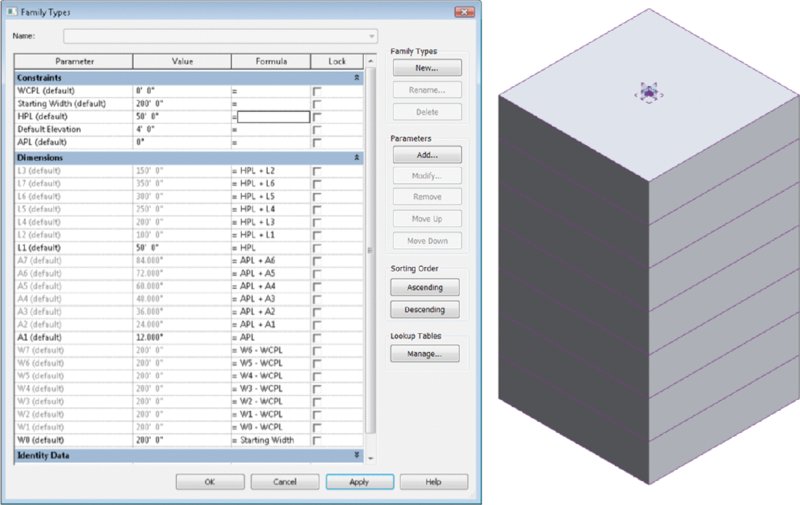
Figure 8.81 Testing the parameters driving the form
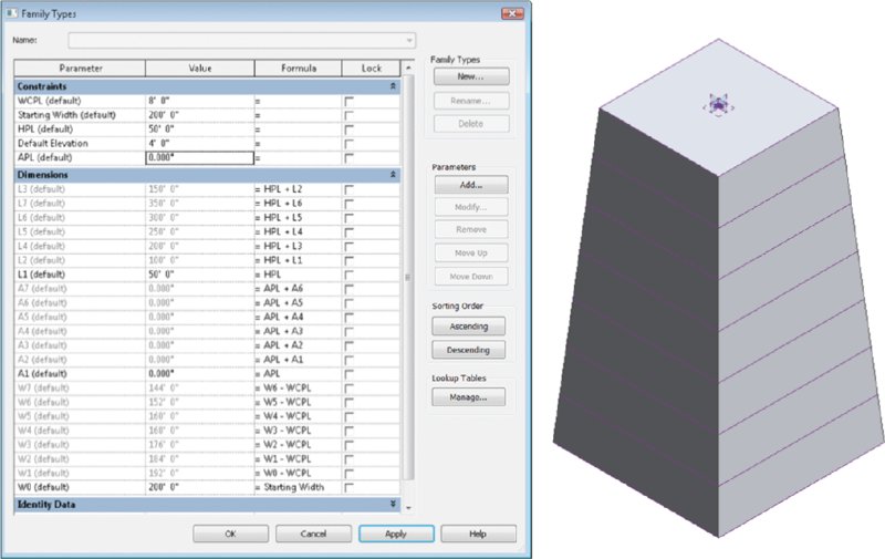
Figure 8.82 Increasing the WCPL instance parameter
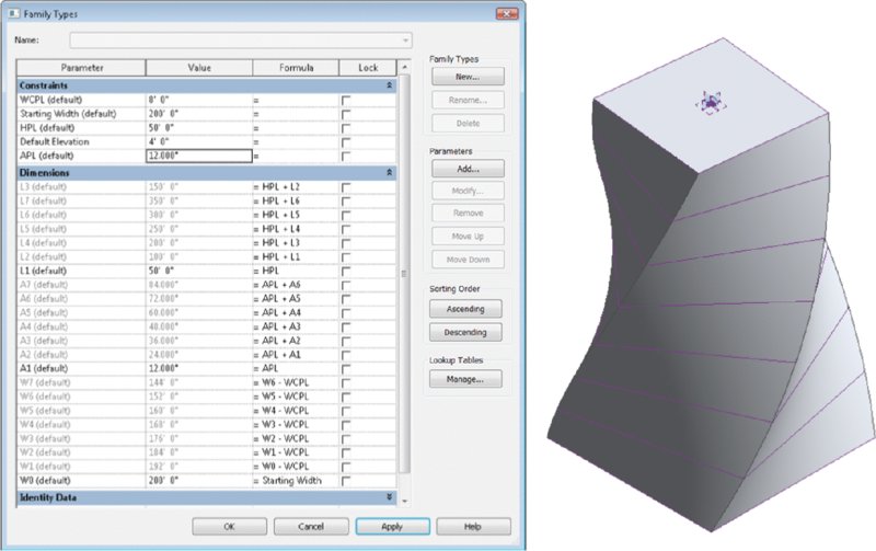
Figure 8.83 Increasing the APL parameter
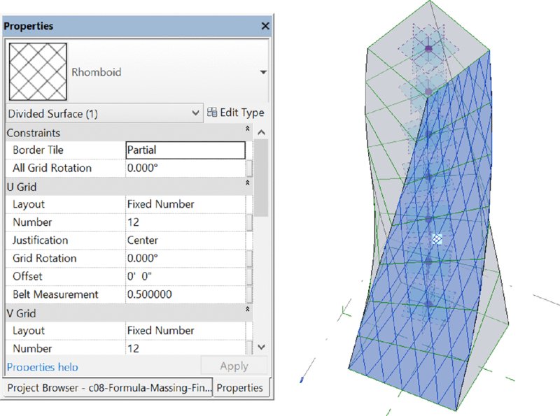
Figure 8.84 Adding patterns to the face of your mass
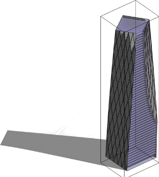
Figure 8.85 Floor area faces
If you want to learn more about expanding the use of the divided surfaces on massing forms, see Chapter 12, “Creating Walls and Curtain Walls.” In that chapter, we discuss the modeling techniques to create custom panel families and how to apply them to pattern-based curtain walls.
Creating interesting and complex massing studies that can be parametrically controlled isn’t just a skill developed over time. The rules that you develop to make and reiterate your designs are also carefully considered aesthetic choices to make decisions rather than blobs! To see this file, go to the Chapter 8 folder and download c08-Formula-Massing-Project_Finished.rvt. Be sure to turn on Show Mass Form And Floors on the Massing & Site tab if it’s not turned on when you open the file.
The Bottom Line
Create and schedule massing studies. Starting the design process with actual building elements can lead to a lot of unexpected frustration. Walls lead to rooms, which get room tags and eventually scheduled. But if you’ve failed to fulfill the client’s program, you’ll wonder where to start over!
Master It You’re faced with creating some design studies of a large hospital complex. How would you go about creating a Revit project that would allow you to create a massing study and schedule it against the design client’s program?
Know when to use solid and surface masses. Solid masses and surface masses can both be used to maintain relationships to host geometry like walls and roofs, but surface masses can’t be volumetrically scheduled or contain floor area faces.
Master It You’ve been asked to create a complex canopy system for the entry to a hotel project. The system will consist of a complex wave of triangular panels. What kind of mass would you create?
Use mathematical formulas for massing. Not all massing is going to involve intuitive, in-the-moment decision making. By discovering the underlying rules that express a form, it is possible to create the formulas that can iterate and manipulate your massing study. So rather than manually manipulating the mass, you manipulate the formulas related to your mass.
Master It What’s the best way to discover and create these formulas?