This appendix provides some tips, tricks, and troubleshooting to help keep your project files running smoothly. Listed here are some pointers to keep you from getting into trouble as well as a peppering of time-savers and other great ideas.
In this appendix, you'll learn to:
Optimize performance
Use best practices
Maintain quality control
Apply tips and shortcuts
Optimizing Performance
It should make sense that a smaller file on a fast computer with a good network will run the quickest. There is no real “typical” project file size for Autodesk® Revit® Architecture projects, and a file can range anywhere from 10 MB to well over 800 MB. We've found that a small, dense project with a lot of geometry and detail (like a medical office building) can be larger in file size than a warehouse project—which has a lot of empty square footage. Because documentation is often an indication of project complexity, we've found as a good rule of thumb that for each documented sheet, your file should be about 1 MB. So a completed project of 100 full-size sheets should be about 100 MB.
Much of the variation depends on the level of detail in the model itself, the presence of imported geometry (2D CAD files, SketchUp, and so on), the number of views you have, and the overall complexity. Obviously, your hardware configuration will also be a factor in determining the speed and operation of your models.
You can optimize your hardware in a number of ways to get the most out of the configuration you have. You should first look at the install specifications and recommended hardware specs for a computer running Revit software. Autodesk has published those requirements on its website, and they are updated with each new version of the software. You can find the current specs at www.autodesk.com/Revit; then choose System Requirements under the list of options on the left.
Beyond the default specifications, you can do things to help keep your files nimble. Here are some other recommendations:
Use a 64-bit OS. Revit Architecture likes RAM, and the more physical RAM it can use, the more model you can cache into active memory. Windows offers several versions of a 64-bit OS, but since Revit 2014, Windows 7 has been a minimum requirement. You can use this in a 32-bit or 64-bit version, but a 64-bit OS allows you to use as much RAM as you can pack into your machine. Note that Windows 8 and 8.1 are also supported.
Get a faster hard drive. Chances are you're working on Revit on a local hard drive. If you're working on a large project with a central file, your local file will be on your hard drive. If you're working on a small project without worksharing enabled, there's a chance you might be working on your local drive if you're taking the file home or if you don't have a network. Regardless, one of the things that will affect performance is your drive speed. This is how fast your computer can read/write to the local drive. With the large files Revit can create, a faster drive will equal less read/write time; so if it's within your budget, try to get the 7,200 rpm drive as a minimum or even an SSD (solid state drive). We've found the SSD, especially in a laptop, is a huge performance boost. You'll appreciate the difference.
Get a good graphics card. Revit is also very graphics-intensive and will push the limits of any video card you have in your computer. Although many graphics cards are available at a variety of performance and price levels, a good starting point is looking for ones that have been tested and approved by Autodesk for use with Revit. You can find recommended system hardware as well as graphics hardware and driver specifications at www.autodesk.com/graphics-hardware-detail.
Figure out how much RAM your project will need. Before you email your IT department requesting 64 GB of RAM, figure out how much you're actually going to use on your project. Your OS and other applications like Outlook will use some of your RAM, but you can calculate how much RAM Revit will need to work effectively. The formula is as follows:
Model size in Explorer × 20 + Linked file size(s) × 20 = Active RAM needed (in megabytes)
Let's look at a couple of examples to demonstrate how it works. You have a Revit file with no linked files, and your file size on your server is 150 MB. So you'll need 150 MB × 20 = 3,000 MB, or 3 GB of RAM just for Revit to operate effectively. In another example, you have a 120 MB file, a 50 MB structural model linked in, and four CAD files at 1 MB each. The calculation is as follows:
Once you've put as much RAM into your workstation as is practical, your next recourse for improving model performance is to reduce your file size so you're not using as much RAM. Here are some tips to do that and thereby improve your file speed:
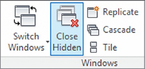
Manage your views. There are two things you can do using views to help improve performance. First, the more views you have open at once, the more information you will load into active RAM. It's easy to have many views open at once, even if you're concentrating on only a few views. Close windows you're not using to help minimize the drain on your resources. You can always close all the windows except your active one using the Close Hidden Windows tool. Choose the View tab and click the Close Hidden button (Figure B.1). You can map a keyboard shortcut to this command such as “XX,” or you can find it in the Quick Access toolbar. The Close Hidden Windows command will close the hidden windows in your active project as well as all other open projects and families in your current session of Revit.
The other way to manage your views is to get rid of the ones you don't need. Revit allows you to make different views within your model quickly and easily. This can sometimes lead to having a lot of views (sometimes hundreds) that you aren't using in your document set and don't plan to use. Adding too many views can raise your overall file size even if you haven't added any geometry or annotations within those views. Get rid of those unused views—typically views that are not on sheets—to help keep your file running smoothly. We discuss how to create a schedule to help identify the unused views later in this chapter.
Delete or unload unused CAD files. There are many times in a project process when you'll want to load content from another source as a background. This could be a client's CAD as-built drawings or a consultant's MEP design. You might link or import these files into your drawing and, during the busy course of the project, forget about them. As you've seen from the earlier tips on RAM use, all these small files add up. Getting rid of them can speed up your Revit project file and is just good housekeeping. If the CAD file is linked, you can remove it using the Manage Links button on the Insert tab. If the CAD files have been inserted instead of linked, right-click an instance of the CAD file in a view and choose Select All Instances from the context menu. Then click Delete to remove all the instances in the entire model as opposed to only the CAD file in the active view.
Don't explode imported CAD files. A CAD file, when imported into Revit Architecture, is a collection of objects that is managed as a single entity. If you explode a CAD file, the single object immediately becomes many objects—and these all take up space in the file, requiring more resources to track and coordinate.
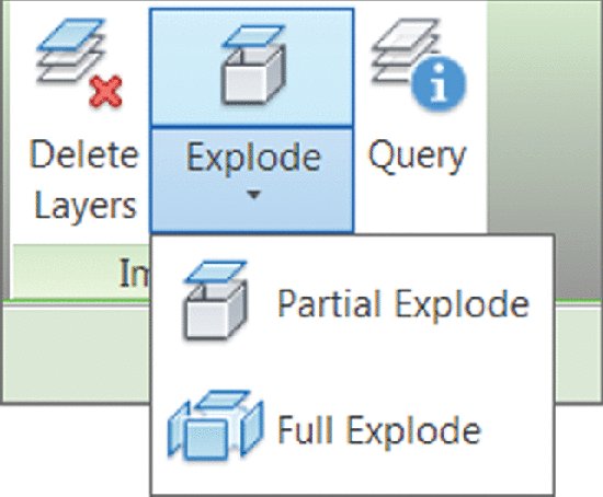
If you're importing DWG files, leave them unexploded as much as possible. If you need to hide lines, use the Visibility/Graphic Overrides dialog box to turn layers on and off. Explode only when you need to change the imported geometry, and start with a partial explode to minimize the number of new entities. Figure B.2 shows the tools available on the ribbon when you select an imported or linked DWG file. Also note that lines smaller than 1/32" (~1 mm) are not retained when CAD files are exploded. This can result in unusable imports.
A better workflow than importing your CAD files directly into the project is to import them into a Detail Component family and then load that family into the project. This approach will also aid in keeping accidents from happening, like a novice user exploding the imported CAD. An example of this workflow is to import a SketchUp model into a mass family and then load the mass family into a project file. This workflow is covered in more detail in Chapter 7, “Interoperability: Working Multiplatform.”
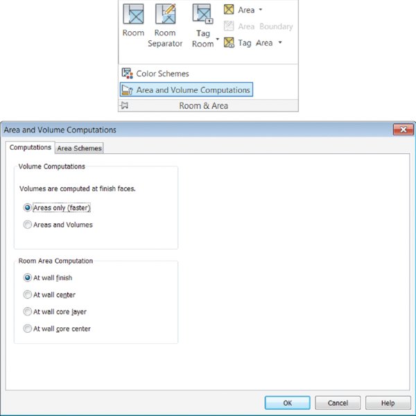
Turn on volume computation only as needed. Calculating the volumes on a large file can slow down your model speed immensely. This setting is typically turned on when exporting to gbXML, but sometimes teams forget to turn it back off again. Volumes will recalculate each time you edit a room, move a wall, or change any of the building geometry. Turn these off using the Area And Volume Computations dialog box found at the bottom of the Room & Area panel on the Home tab (Figure B.3).
Figure B.3: Choose the area calculations to minimize unneeded computations.
Use Best Practices
Good file maintenance is critical to keeping your files running smoothly and your file sizes low. The following are some best practices and workflows that were identified in other areas of the book but are consolidated here as a quick reference:
Manage the amount of information shown in views. Learn to manage the amount of information needed in a given view. Minimize the view depth and the level of detail so you don't show more than you need to show in a view. Here are some simple tips to keep your individual views working smoothly:
Minimize the level of detail. Set your detail level, found in the view control bar, relative to your drawing scale. For example, if you're working on a 1/32" = 1'-0" (1:500) plan, you probably don't need Detail Level set to Fine. This will cause the view to have a higher level of detail than the printed sheet can show, and you'll end up with not only black blobs on your sheets, but views that are slow to open and print.
Minimize view detail. Along with the amount of detail you turn on in the view using the Detail Level tool, make sure you're not showing more than you need to. For instance, if you have wall studs shown in a 1/16" = 1'-0" (1:200) scale plan or the extruded aluminum window section shown in a building section, chances are it will not represent properly when printed. Turning off those elements in your view will keep things moving smoother as well as printing cleaner.
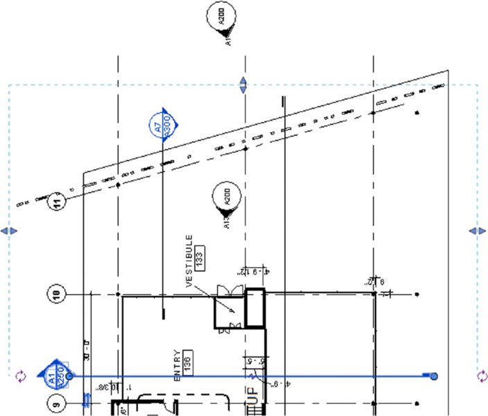
Minimize view depth. View depth and crop regions are great tools to enhance performance. As an example, a typical building section is shown in Figure B.4. The default behavior causes Revit to regenerate all of the model geometry to the full depth of that view every time you open the view. To reduce the amount of geometry that needs to be redrawn, drag the section's far clip plane (the blue dashed line when you highlight the section) in close to the cutting plane.
Model only what you need. Although it is possible to model to a very small level of detail, don't fall into the trap of over-modeling. Be smart about what you choose to model and how much detail you plan to show. If it's not conveying information about the project, maybe it's not really needed. The amount of information you do or do not model should be based on your project size and complexity, your timeframe, what you need to document, and your comfort level with the software.
How much to model: Use these three rules of thumb. When trying to decide how much detail to put into a model or even a family, there are three good rules of thumb to help you make the right decision for the particular element you're looking to create:
Scale What scale will this detail be seen in? If it's a very small-scale (such as 3" = 1'-0"), it might be simpler to just draw it in 2D in a drafting view.
Repetition How many times will this detail appear in the drawing set? If it will appear in only one location or only one time, it might be easier to just draft it in 2D rather than try to model the element. If it will appear in several locations, modeling is the better solution. The more exposure an element has in the model (the more views it shows in), the more reasons you have to model it. For example, doors are good to model. They show in elevations and plans all over the sheet set.
Quality Be honest—how good at modeling families are you? Don't bite off more than you can chew. If you're new to the software, keep it simple and use 2D components. The more projects you complete, the better you'll understand the transition to a BIM workflow.
Don't over-constrain. Embedding user-defined constraints into families and the model helps keep important information constant. However, if you don't need to lock a relationship, don't do it. Over-constraining the model can cause problems later in the project process when you want to move or modify locked elements. Constrain only when necessary. Otherwise, let the model be free.
Watch out for imported geometry. Although you have the ability to use geometry from several other file sources, use caution when doing so. Remember that everything you link into a project or a family takes up around 20 times the file size in your system's RAM. So linking a 60 MB NURBS-based ceiling design will equal 2 GB of RAM and more than likely slow down your model. Deleting unused CAD files, using linking rather than importing, and cleaning up the CAD geometry before insertion will help keep problems to a minimum.
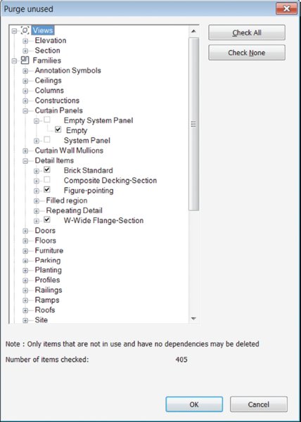
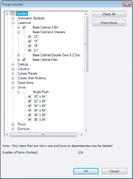
Purge unused files and family types. You will find that you won't use every family, group, or material you create in your model. Revit Architecture has a tool that will allow you to get rid of those unused elements to help keep your file sizes down to a reasonable level. This tool, Purge Unused, can be found on the Manage tab in the Settings panel. If your file is very large, it can take several minutes to run, but eventually you'll be presented with a list (Figure B.5) of all the unused elements within your file.
Figure B.5: Use the Purge Unused dialog box to reduce file size.
We'll discuss the Purge Unused command in greater detail later in this appendix.
Model correctly from the beginning. As you refine your design, it's critical to model correctly right from the beginning, not taking shortcuts, so you don't have to fix things later. If you can begin by thinking about how your project will be assembled, it will save you a lot of time later in the process. It's good practice to plan ahead, but remember that the software will allow you to make major changes at any stage in the process and still maintain coordination. If you are still in an early phase of design and do not know the exact wall type, use generic walls to capture your design intent; changing them later will be simple.
Manage workshared files. When employing worksharing on a project, there are additional tools and tips you'll want to follow. Check out Chapter 5, “Working in a Team,” for more details.
Make a new local copy at least once a week. In a workshared environment, your local copy can begin to perform poorly or grow in file size while the central file remains small and nimble. If this is the case, it might be time to throw out the old local copy for a new one. Keep in mind that Revit allows you to make a new local copy upon opening the central file. When you choose a central model from a network location, Revit will automatically make a new local copy and place it in your Documents folder. If you choose not to follow that workflow, keep in mind that if you're accessing a project on a daily basis, it's a good idea to make a new local copy at least once a week.
Divide your model. For larger projects or campus-style projects, you can break up your model into smaller submodels that are linked together. You can also do this on a single, large building, although it is a bit more complex. Dividing a model helps limit the amount of information you are loading into a project at one time.
This is a particularly good idea if your project is going to be delivered in separate phases or bid packages. As the project progresses and you complete each delivery, you'll start the next phase by creating a new project file and then linking in the previous project file as context. Doing so will greatly simplify your document set (because you'll be able to start over after each phase) and avoid inadvertently modifying the previous phase (since the geometry and documentation are in a linked file).
If you decide to divide your project, make your cuts along lines that make sense from a holistic-building standpoint. Don't think of the cuts as you would in CAD, but think about how the actual assemblies will interact in the building. For example, don't cut between floors 2 and 3 on a multistory building unless you have a significant change in the building form or program. A good place to cut might be between the building and the adjacent parking garage. Here's a list of some good places to split a model:
At a significant change in building form or massing
At a significant change in building program
Between separate buildings on the site
At the building site
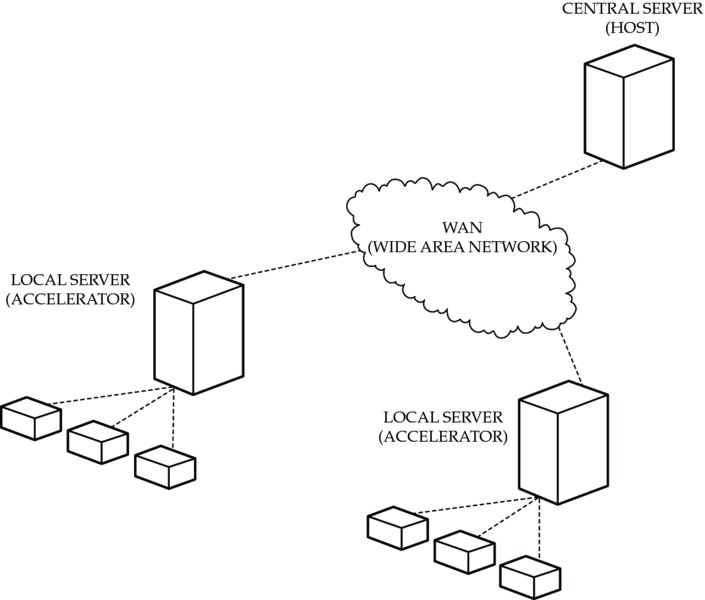
Don't want to divide your model? Use Revit Server. Revit Server is an add-on you can install that allows you to layer your central file over multiple locations. Effectively it allows a file server to synchronize a central file in the same way workstations sync a central file. Figure B.6 diagrams a Revit Server installation. Each installation has a host server. That host server synchronizes the central file between one or more accelerators, and those accelerators handle the traffic to the workstations. Depending on your installation, the host server might also be the accelerator for that particular office. Think of the host and the accelerator as tasks, not necessarily as separate servers.
There are a few situations where Revit Server is a great solution. Imagine you are working in a larger office and you have teams in multiple locations. Say you have an office in New York and one in Los Angeles. Both teams want to work on the same project within the same Revit file, but there is too much latency across the network at that distance to make using Revit between the offices practical. You would use Revit Server. You'd install a host in one location and an accelerator in the other. Or imagine that you have partnered with another architecture firm to do the design of a project. Both of you need to be involved in the project and want to work within the same model. You'd use Revit Server again—with the host in one office and the accelerator in the other office. Where Revit Server won't be effective is if your project file is simply large.
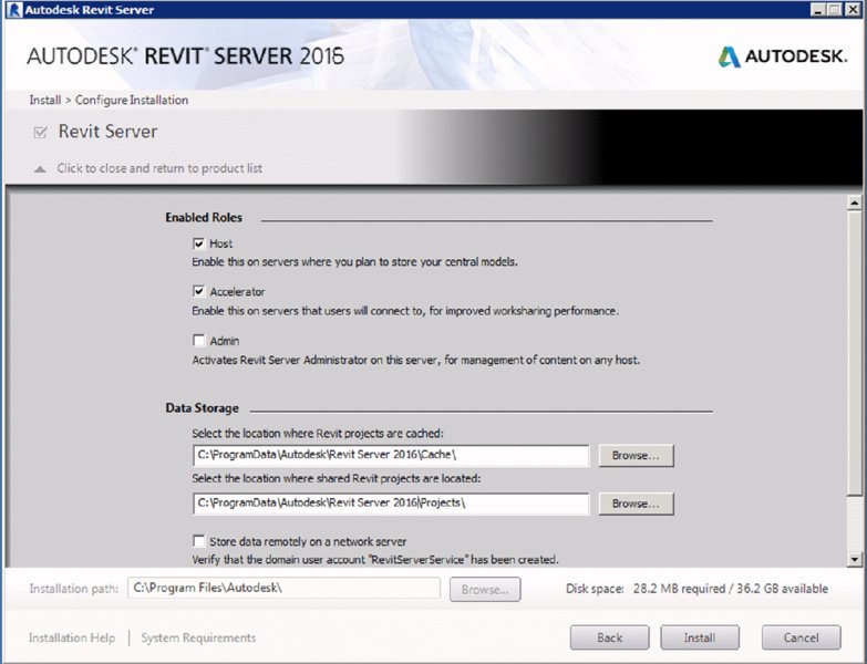
Installation of Revit Server is quite easy, but it does require the help of your IT department. To begin, you'll need to download the Revit Server installer from your subscription site, and the installation needs to be done on a computer running Windows Server 2008 R2 or newer. To install the host, run the install package and on the Configure Installation screen under Enabled Roles, choose Host and Accelerator (Figure B.7). This will cover your primary location. For your secondary location, you'll need a Windows Server 2008 R2 or newer running just the accelerator.
The installation package is pretty quick, so don't be thrown off when it's completed. To point the computers at each other and make the connection, you'll need to add a simple INI file. On each computer (host, accelerator, and all the workstations) navigate to C:ProgramDataAutodeskRevit Server 2016Config. That folder will initially be blank. Create a TXT file by right-clicking within the folder and choosing New Text Document from the context menu. In the document, type the IP address of the host server (for example, 10.0.0.110). Close the document and save the file as RSN.txt. As a final step, change the extension from .txt to .ini.
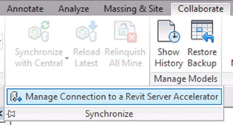
With that complete, you're done with the server configurations. As a final step, you need to point your workstations to the accelerator. Open Revit and on the Collaborate tab, choose the drop-down menu and select Manage Connection To A Revit Server Accelerator (Figure B.8).
Figure B.8: Revit Server Accelerator configuration
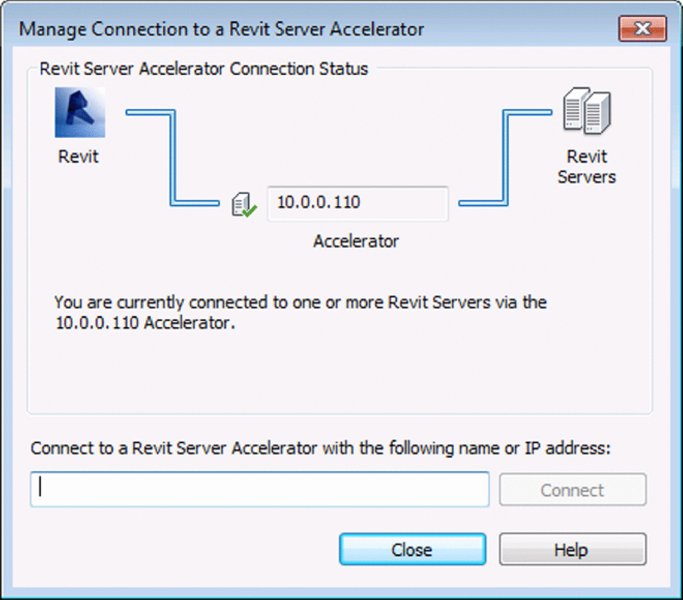
In the Manage Connection To A Revit Server Accelerator dialog box (Figure B.9), enter the IP address of your local accelerator. Depending on your environment, the accelerator and the host can be the same server. Choose Connect and the link will be established.
Figure B.9: Creating the connection to the Revit Server Accelerator
Now you're all set! To use the Revit Server, you'll just need the final step of saving your central file to the Revit Server location. Open your central server and choose File Save As. In the Save As dialog box, you'll notice a new location on the left: Revit Server. Save your central file to that location and it will be accessible by all your team members.
Don't want to Use Revit Server? Use Autodesk¯ A360 Collaboration for Revit¯. If you're in a smaller office, you might not have access to Windows Server 2008, but you still need a way to collaborate with your partner firm or other project team members. Autodesk has a tool in Revit 2016 called A360 Collaboration for Revit. It is a paid service that allows you the same functionality as Revit Server, but without the need to manage the installation process across your network. In lieu of your files being saved on your Revit Server installation, the central file resides on the Autodesk¯ A360 website. For more information about the service, visit www.autodesk.com/products/collaboration-for-revit/overview.
Quality Control
In any project process, you should always maintain a level of quality control to ensure a solid workflow. When working in a BIM environment, good model maintenance is an imperative part of the process. A well-maintained model will open quickly and be responsive when you're changing views or manipulating content. A model that is not well maintained can have a very large file size, take a long time to open or save, or even become corrupted. Letting the quality of your model suffer can negatively impact the team's overall production and lead to frustration because they cannot be as efficient as they'd like to be. The model size will grow, it will take a long time to save locally or SWC (Synchronize With Central), and the file can suffer corruption or crashes.
Maintaining a good, healthy model is not difficult. It takes about as much effort as regularly changing the oil in your car. The important thing, as with your car, is actually doing the regular maintenance so you don't have to fix a bigger problem that could have been avoided. In the following sections, we'll cover some simple things you can do using the tools already built into Revit software.
Keeping an Eye on File Size
The size of your file is a good metric for general file stability. A typical Revit file size for a project-in-construction will be between 100 MB and 500 MB. Note that 500 MB is really on the high side of file sizes; beyond that, the model will be slow to open and hard to rotate in 3D views. Other views, such as building elevations and overall plans, will also be slow to open.
Should your file become large or unwieldy, you have several ways to trim your file and get your model lean and responsive again. We've discussed some ways to make your computer faster to accommodate larger files sizes. Now, let's discuss ways to optimize the file itself.
PURGING UNUSED FAMILIES AND GROUPS
On the Manage tab is a command called Purge Unused. This command removes all the unused families and groups from your model by deleting them. There are many times in a design process when you will change window types or wall types or swap one set of families for another. Even if those elements are not being used in the project, they are being stored within the file, and therefore, when the file is opened, they are being loaded into memory. Depending on the stage of your project, you should periodically delete these elements from the model to keep your file size down. Don't worry—if you find you need a family you've removed, you can always reload it.
Select the Manage tab and choose Purge Unused from the Settings panel. Depending on the size of your model and how many families you have loaded, it might take the software a few minutes to complete this command.
After the software is done thinking, it will provide you with a list of all the families and groups in the file that are not actively within a view (Figure B.10). At this point, you have the option to select the elements you want to delete or keep, and remove the rest. You can select either entire families or just unused types. Notice that some of the families cannot be selected for deletion, because they are either nested in another family or other types of that family are already being used in your project.
In addition to families, unused materials and property sets can be removed using the Purge Unused command. Imported categories can be purged as well; however, you don't have the option to choose which ones to delete.
We don't recommend that you use this command in the early stages of design, because your file size won't be that large early on, and purging would eliminate any preloaded families that you might have included in your template. During schematic design and design development, you are typically going through design iteration and will likely be adding and removing content regularly. It can become a hassle to have to constantly load or reload families into the model. If your model is not suffering from performance issues or the file size isn't unruly, it's not necessary to perform a Purge Unused.
You might also consider using the Save Families tool before purging all unused families. From the Application menu, click Save As Library Family and you can export all of the families in your project to a folder. After you purge unused families, you can always return to the folder in which you saved the families and reload them as necessary.
CUTTING DOWN ON THE NUMBER OF VIEWS
The ability to quickly create views within a model is one of the benefits of using Revit; however, this ability can be a detriment if it is not managed. Beyond the simple hassle of sorting through many views to find the one you need, too many views can also negatively affect your performance and file size.
Obviously, a number of views are needed within the model to show design intent and create the construction documentation. Beyond those views, you will find yourself creating views to study the design, deal with model creation, or simply view the building or project from a new angle. These types of working views will never make it to the sheet set, and some will be used for only brief periods.
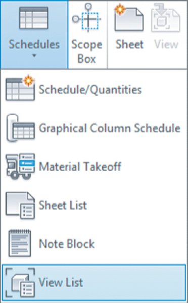
Before you go through the effort of counting all your unused views, remember that a Revit model is a database. You can use this feature to let the software perform the counting for you, using schedules. To create a schedule that will track unused views, open the AppB-Foundation.rvt file found on the book's web page at www.sybex.com/go/masteringrevitarch2016. Next, select the Schedules flyout from the View tab and choose View List.
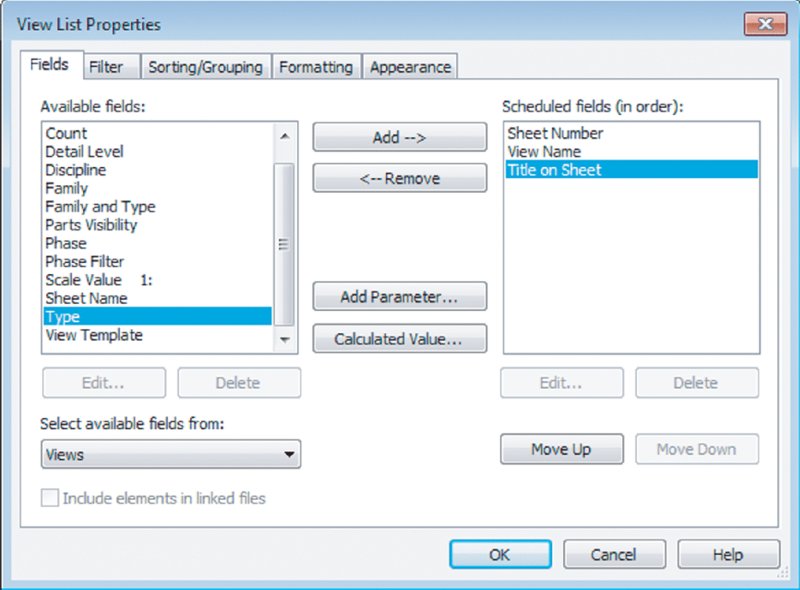
The View List Properties dialog box allows you to select the fields you want to have in your schedule. For your View List schedule, select the following fields (in order):
Sheet Number
View Name
Title On Sheet
Use the Add button to move those fields from the left column to the right one and sort them in the order listed (Figure B.11).
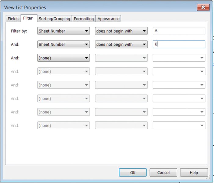
If you were to click OK right now, you'd create a schedule of all the views you have within the model. Since you want to see only the views that are not on sheets, you have a bit more formatting to do. By selecting the Filter tab, you can choose to see only the views not placed on sheets. In the Jenkins model, there are two sheet types: those that begin with an A and ones that begin with a K.
On the Filter tab, choose to filter the sheets by sheet number.
From the drop-down menu, choose Does Not Begin With as a filter type.
Finally, in the text field, enter a capital A (Figure B.12).
Remember that because these are database functions, they are also case sensitive. Before moving on to the next tab, choose to add another filter selection. Copy the one you just created to filter A sheets, but now filter out all the K sheets.
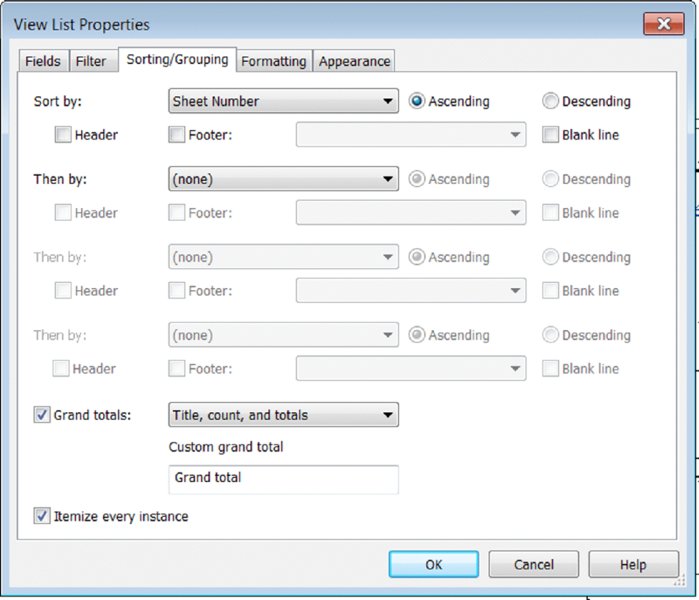
As a last bit of formatting, select the Sorting/Grouping tab. On this tab, from the drop-down menu select Sheet Number. Should you have missed a sheet number type (for instance, if you have G sheets in your list), it would appear at the top. Be sure to have the Grand Totals and the Itemize Every Instance check boxes selected (Figure B.13). Click OK when you've finished.
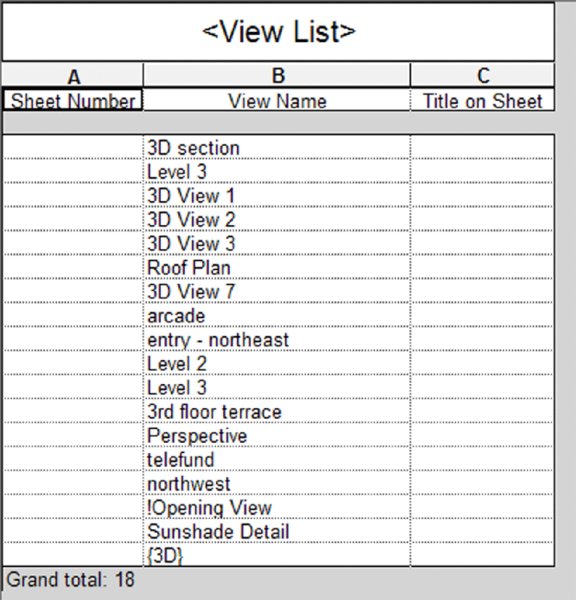
The result of this exercise will be a schedule that looks similar to Figure B.14; it shows a list and the total of all the views not on sheets in your model. You can see that in our model we have 19 views not currently on sheets. No matter how many views you have in this schedule, you'll want to be selective about what you eliminate and what you choose to keep. Just because a view is not on a sheet, that doesn't mean it doesn't have value to your project. Ideally, someone familiar with the project will assess the value of the views in this schedule to determine what to keep and what to remove.
It is also a good idea to add this schedule to your office template where it will keep a running list of views not on sheets that you can refer to at any time in the project process.
Using Schedules
As you saw in the previous example, using schedules is a great way to use tools already in the software to perform quality control on your projects. Don't think that all schedules need to be placed on sheets. There are several uses for schedules as a quality assurance measure. In the previous example using views, you used schedules to help troubleshoot poor model performance; however, you can use schedules to help you control quality for all kinds of things. The following sections highlight two more examples.
MULTICATEGORY SCHEDULES
An excellent way to monitor the contents of your building model is through the use of multicategory schedules. For the purpose of quality control, you might not be too concerned with extensive quantity takeoffs. Thus, you will need to create a schedule with a limited number of fields, organized in a way that doesn't list each and every object instance in the project. We'll show you how to do this in the following exercise:
Continuing with the AppB-Foundation.rvt file, go to the View tab in the ribbon, click the Schedules flyout, and select Schedule/Quantities.
Choose <Multi-Category> at the top of the Category list and change the name to Multi-CategoryQA Schedule.
In the Fields tab of the Schedule Properties dialog box, add the following fields (in order) to the Scheduled Fields list:
Category
Assembly Code
Assembly Description
Family And Type
Count
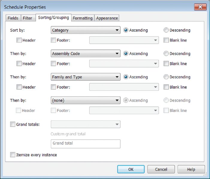
Switch to the Sorting/Grouping tab, set the first sorting parameter to Category, and select the Header option. For the second sorting parameter, choose Assembly Code, and set the third sorting parameter to Family And Type. Finally, uncheck the Itemize Every Instance option at the bottom of the dialog box (Figure B.15).
Figure B.15: Specify the sorting and grouping options for the multicategory schedule.
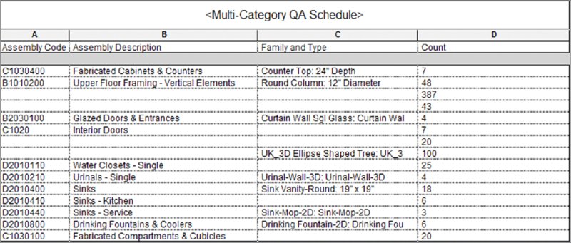
Switch to the Formatting tab and select the Category field. Check the box to make it a hidden field and then click OK to view the results (Figure B.16).
Figure B.16: The multicategory schedule shows all elements in the project.
With this type of schedule, you can manage the entire scope of contents actively placed in your model. Objects that don't have the proper assembly codes can be corrected in this schedule. For other issues such as family- or type-naming conventions, you will need to make those adjustments in the Project Browser. In addition to verifying that the correct content has been used throughout your project, you can check the Count field for rows where a small number of elements have been placed—perhaps indicating that a family has been placed in error.
NOTE Another way to save your schedules is to simply right-click them in the Project Browser and choose Save to New File. This will export the schedule to an RVT file and is a good way to save any view type.
KEYNOTES
As a final example illustrating the use of schedules to manage the consistency of a project, we'll discuss how to use keynotes in the construction document process. Regardless of whether you use numerical keys or text-based keys, you will invariably need to use one of them to add annotations to your project. Although the software can easily produce both types of annotation, for the sake of ease and consistency we will refer to them as keynotes for the remainder of this section because that is the name of the Revit command.
If you are keynoting a project, you are adding annotations that call out specific materials or conditions within your details. Those notes not only need to be consistent across multiple details, but they will also link directly back to the project specifications—a separate set of documents published outside of the Revit environment. Historically on a project, to maintain any sort of consistency between notes in different views, you needed to manually coordinate all the notes and manually check them. When you are talking about hundreds of sheets in a drawing set and thousands of notes, there is plenty of room for error. In a manual process, you can have notes on one sheet that read “Cast-in-Place Concrete,” whereas on another sheet they read “CIP Concrete,” and on a third sheet “Cst in Place Conncrete” (note the typos).
The Keynote tool has some built-in checks and balances to ensure a level of consistency when it is being used, and we explore the tool further in Chapter 18, “Annotating Your Design.” However, it should be pointed out that a keynote legend is another good way for the project manager to maintain a level of oversight throughout the project. A keynote legend will give you a running list of what notes are being used in a project—even though it is intended to be placed on sheets to complement your documentation. This overall list can also be cross-checked against the specifications so you can ensure that everything you've added to the model has a corresponding section.
To create a keynote legend, follow these steps:
On the View ribbon, select the Legends drop-down, and choose Keynote Legend.
The fields for a keynote legend are limited to Key Value and Keynote Text.
Switch to the Filter tab and you will notice an option unique to this type of legend. Check the box labeled Filter By Sheet if you want the legend to display only the keynotes shown within the same sheet on which the legend is placed. Remember, you can place a legend on as many sheets as necessary.
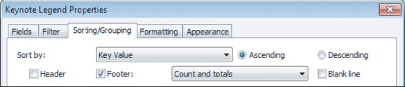
In the Sorting/Grouping tab, you have one additional option to help you review the keynotes used in your project. If you select the Footer option and choose the Count And Totals option (Figure B.17), you can view how many times each keynote is used throughout your project. Remember that this option will also affect the instances of the keynote legend already placed on sheets. Use this option sparingly and disable it after your quality control tasks.
Figure B.17: Use the Footer option to show a count of each keynote.
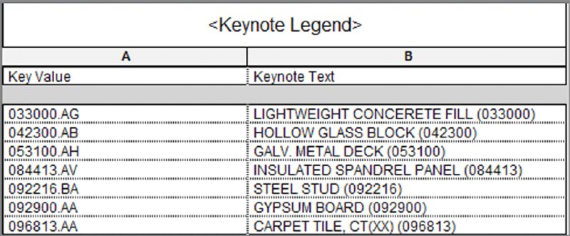
The finished schedule will look like Figure B.18. If you look at the elements displayed in the schedule, you'll notice that it is organized by Construction Specification Institute (CSI) division, and every note will be listed so you can verify the spelling and accuracy of each item.
A seemingly obvious place to troubleshoot your model is the Review Warnings tool. Although this technique will do very little to affect your overall file size, the Warnings dialog box will alert you to problems within the model that should regularly be addressed to ensure file stability. To locate this dialog box, go to the Manage tab in the ribbon, find the Inquiry panel, and click the Warnings button.
Selecting this tool will give you the dialog box shown in Figure B.19, which lists all the warnings still active in your project file.
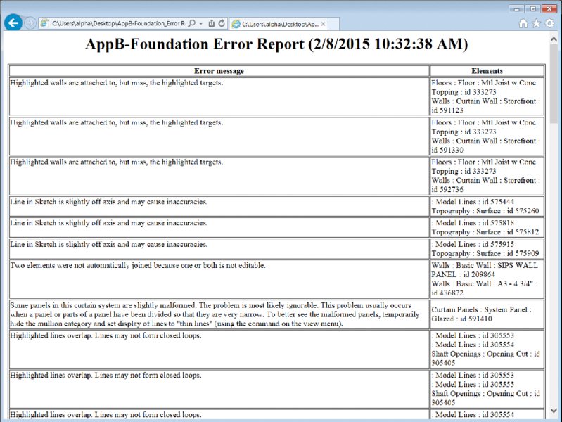
Warnings are notifications of all types of issues the software has resolving geometry, conflicts, or formulas that do not equate. Examples of things that will appear in this dialog box are instances where you have multiple elements sitting directly on top of each other, thereby creating inaccurate schedule counts; wall joins that do not properly clean themselves up; wall and room separation lines overlapping; stairs that have the wrong number of risers between floors; and so on. This dialog box shows you all the times the yellow warning box appeared at the bottom-right corner of the screen and you did not take action to solve the problem. Warnings that go unchecked not only can compound to create other errors, but can lead to inaccurate reporting in schedules or even file corruption. You'll want to check the Warnings dialog box regularly as part of your periodic file maintenance and try to keep the number of warnings to a minimum. You might also notice that the dialog box has an Export feature. This feature exports your warning list to an HTML file, allowing you to read it at your leisure outside the model environment (Figure B.20). Pulling this list into a Microsoft Word or Excel document allows you to distribute the warnings across the team for them to be resolved.
In the example shown in Figure B.20, we have 47 warnings in the file. How many warnings in a file are too many? That depends on your model, computer capabilities, what the warning types are, and your deliverable. For instance, if you are delivering a model to your client or to the contractor, you might have a zero-warning requirement. In that case, all warnings must be resolved prior to delivering the model. If you are still actively in the design phase of the project, however, you will always have some warnings—it is an inescapable part of the process of iteration. As you refine the drawings, problems will be resolved, and as you add new content to the model that is in need of resolution, new ones will be created. If you are not worried about a model deliverable, you can get away with having fewer than 1,000 warnings in the project without too much trouble. That said, the cleaner the model, the smoother it will run.
Another option for finding and resolving warnings is available in the contextual tab of the ribbon. When you select one or more objects that have warnings associated with them, you will see the Show Related Warnings button at the end of the ribbon. Click this tool to display the warning dialog box, and only the warnings related to the selected elements will be displayed. This is a good way to resolve model issues as you and your team develop a project. Being proactive about model quality will save you time in the long run. As Benjamin Franklin once said, “An ounce of prevention is worth a pound of cure.”
Other Tips and Shortcuts
Beyond all the things you can do to hone your skills, you will begin to learn a number of tips and shortcuts as your experience grows using Revit Architecture. Here is a compilation of some of those tips and tricks:
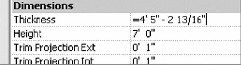
Let the software do the math. Revit Architecture is like a big calculator, and it's very good at doing math correctly. Don't want to spend the time trying to figure out what your room size is after you subtract a 3 5/8" stud and 5/8" piece of gypsum board from an 11'-2" room? Don't. If you need to modify a dimension, simply add an equal sign and a formula (Figure B.21), and Revit will calculate the value for you. You can do a lot of math within the Properties palette. Revit will support everything from simple calculations to the more complex Boolean equations.
Figure B.21: Use an equal sign for performing calculations.
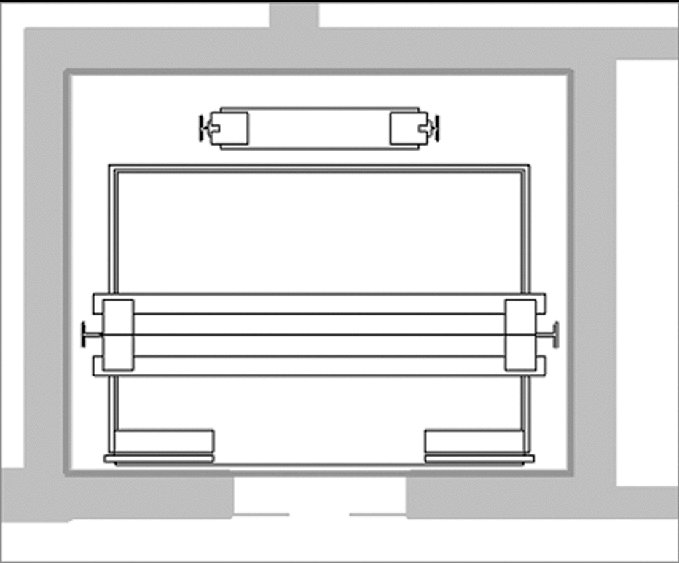
Make elevators visible in your plans. You want to create a shaft that will penetrate all the floors of your building and put an elevator in it that will show in all your plans. You could do that with an elevator family and cut a series of holes in the floors by editing floor profiles, but sometimes those holes lose their alignment. Fortunately, you can do both things at once using the Shaft tool found on the Opening panel of the Architecture tab. Here, not only can you cut a vertical hole through multiple floors as a single object, but you can also insert 2D linework to represent your elevator in plan (Figure B.22). Every time the shaft is cut in a plan view, you will see the elevator linework.
Orient to view. Creating perspective views of isolated design elements can be quick and easy in a plan or section, but let's say you want to see that same element in 3D to be able to work out the details. Here's how:
Create a plan region or section cut isolating the area in question. If you're using a section, be sure to set your view depth to something practical.
Open the Default 3D view or any axon of the project.
Right-click the ViewCube®, select Orient To View, and select your view from the context menu.
Now, your 3D view will look identical to your section or plan region, but by rotating the view, you'll be able to see that portion in 3D.
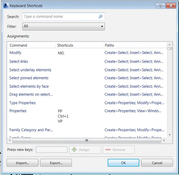
Tune your shortcuts. You can edit your keyboard shortcuts without the hassle of rooting through your hard drive looking for a TXT file. To edit your shortcuts, click the Application menu and select Options. Choose the User Interface tab and then click the Customize button. The Keyboard Shortcuts dialog box (Figure B.23) will allow you to edit those shortcuts. Consider making common shortcuts the same letter. So instead of pressing VG to get to your Visibility/Graphic Overrides dialog box, make the shortcut VV for quicker access.
Drag and drop families. You need to load a family into a project, you have the Explorer window open, and you know where the family is, but you don't want to go through the laborious effort of navigating across your office's server environment to get there. No problem. You can drag and drop families from Explorer directly into the project file.
Double-click families to edit. You no longer need to highlight a family and then mouse all the way to the ribbon to choose Edit Family. If you want to edit the family, simply double-click it and the family will launch in the Family Editor. You can customize other double-click settings in the Options dialog box, accessed on the Application menu.
Double-click the mouse wheel to activate the Zoom To Fit command for even faster view navigation!
Copy a 3D view. You made the perfect 3D view in your last project, and you can't figure out how to get it into your current project. Fortunately, there's a way to copy views from one project to another. Open both files in the same running instance of the software and then follow these steps:
In your perfect view, right-click the 3D view in the Project Browser and choose Show Camera from the context menu.
Press Ctrl+C to copy the selected camera.
In your new model, use Ctrl+V to paste the camera, and your view and all its settings are now there.
Use a quick-cut poché. Want to change everything that's cut in a view without having to select every family and change its properties? A quick-cut poché is, well, quick:
Open the view you want to modify.
Using a crossing window, select all the elements within the view.
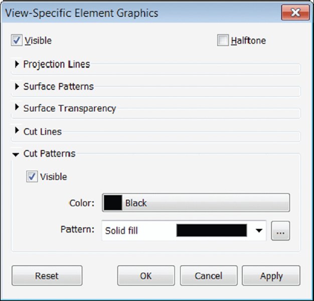
Right-click and choose Override Graphics In View By Element from the context menu. As shown in Figure B.24, you can choose any filled region in the project and assign it to anything that is cut within your model.
Figure B.24: Using Override Graphics for a quick-cut poché
Move your ribbon. Did you know that you can reorganize the tabs on the ribbon and place them in any order you'd like? Hold down the Ctrl key and select a tab (like Insert). You can drag it left or right to change the order in which they appear.
Additional Resources
A number of resources are available to help you along the way to improve your Revit Architecture skills, solve problems, or create new content. In our digital age, there is a wealth of information online to help you learn or communicate with users far and wide. So before you spend hours trying to solve a particularly challenging problem on your own, you might check some of these tools:
Help Clicking the question mark icon in the upper-right corner of the application will take you to the Autodesk Help site at http://help.autodesk.com/view/RVT/2016/ENU. This site will give you a basic synopsis of all the tools, buttons, and commands available in the application. If you don't wish to use the online help resource, you can switch to the traditional local help file by searching your computer for the version of the Revit.ini file specific to your version of Revit software. For the individual user, the Revit.ini is located here:
The value for HelpFileLocation in the example above may vary, depending on the localized version of the software or modifications to the default installation path. You can also change the HelpFileLocation variable to any location on your company's server.
UseHelpServer can be set to 0 for offline help or to 1 for online help. HelpBrowser is an integer that controls the Internet browser used when calling the help content. Set this variable to 0 to use the default browser or to 1 to always use Internet Explorer. The variable OnlineHelpLocale can be used to direct links to online help into a specific language. Use a locale designation such as enu for English-United States or fra for French.
Subscription Support If you have purchased Revit Architecture on subscription, Autodesk offers web-based support. Autodesk's responses are speedy, the advice is top-notch, and chances are your problem has been seen before. Subscription Support can be accessed online at http://subscription.autodesk.com.
AUGI Autodesk User Group International (AUGI) is a source for tips and tricks as well as excellent user forums. The forums are free to participate in, and they're a great place to ask questions, find answers, or discuss project workflows. AUGI is located online at www.augi.com. Once you're there, head to the AEC forums.
YouTube Here's a great reason to tell your IT department you need access to YouTube. Autodesk has its own channel that has some great content, it's free, and it has hundreds of short videos showing you how to perform specific tasks in Revit. See www.youtube.com/user/autodeskbuilding.
AECbytes AECbytes is a website dedicated to following the trends in the AEC industry, with a strong focus on BIM, technology, and the direction of the industry, put together by Lachmi Khemlani. See www.aecbytes.com.
RevitForum RevitForum is a user-based forum for all the Revit questions you could ever ask. It has international membership and language translation. It's a great resource where you can ask questions and receive feedback; see www.revitforum.org.

 Reviewing Warnings
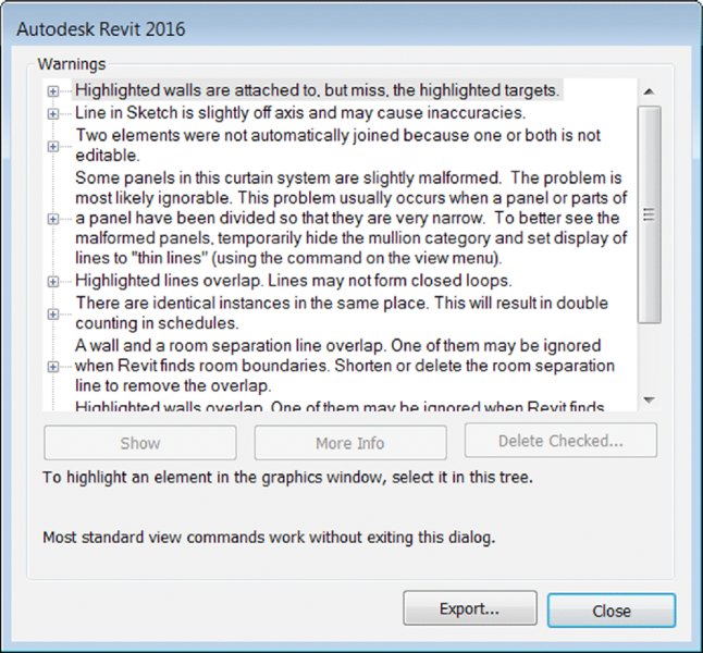
By Element from the context menu. As shown in Figure B.24, you can choose any filled region in the project and assign it to anything that is cut within your model.