In this chapter, we will explore the use of Autodesk® Revit® Architecture software in the construction phase by design teams and builders. For design teams, the use of Revit Architecture usually entails markups, sketches, and revision management; however, a builder may approach building information modeling (BIM) tools in unique ways. Many different BIM programs are available for builders to use in preconstruction and construction phase tasks, so we will not assume that Revit is the primary tool used by the majority of them.
In this chapter, you’ll learn to:
Add revisions to your project
Use digital markups
Model for construction
Using Revisions in Your Project
Revisions allow designers and builders to track changes made to a set of construction documents during the construction phase of a project. Because the construction documents usually consist of numerous sheets, this methodology allows everyone on the team to track and identify which changes were made and when they were made during construction. The purpose is not only to ensure correct construction but also to create as-built documentation recording how the building was actually created to be delivered to building owners upon occupancy.
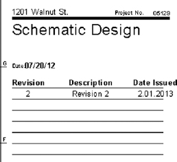
In a typical drawing set, revisions will look like Figure 19.1 when they are created and issued as part of the drawing set. Revision clouds themselves are created within views that are placed on the sheets. The revision tag is also placed within the view, but once the view is then placed on a sheet, the revision will dynamically appear in the sheet properties and on any revision schedule on the sheet itself.
To create a revision cloud in your project, switch to the Annotate tab in the ribbon, locate the Detail panel, and then choose Revision Cloud. This places you in a revision cloud drawing mode, similar to Sketch mode, and allows you to bubble the revised detail or drawing. When you finish, click the green check mark to complete the sketch and your annotation is done. We’ll step through this in more detail later in this chapter.
You will usually have several rounds of revisions to a document set. Revit provides a way to manage the revision list and gives you the ability to name and date the various revisions in your project to better track them. The Sheet Issues/Revisions tool is located in two places within the application. You can find it on either the View tab in the Sheet Composition panel or the Manage tab under Additional Settings.
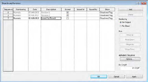
Either one of these buttons will open the Sheet Issues/Revisions dialog box (Figure 19.2). Here you can add, merge, issue, and define the visibility of revisions.
Before you begin creating revisions in your sheet set, it’s good to start with this dialog box to give those revisions some order. Let’s review the major components of the Sheet Issues/Revisions dialog box, beginning with the table of revisions:
Table of Revisions The Sheet Issues/Revisions dialog box starts with one default revision already in place, even though you may not have made a revision yet. This is only to give you a place to start—no revision will appear in your title blocks until you add revision clouds to your views. Each revision has a fixed number of parameters that you can enter. As you can see in Figure 19.2, the parameters include Numbering, Date, Description, and an Issued check box in addition to Issued To and Issued By columns and options for showing clouds and tags.
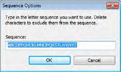
Numbering (Table Column) The Numbering option allows you to number each revision numerically, alphabetically, or not at all. If you choose an alphabetic sequence, the sequence is defined in the Alphabetic Sequence options. Click the Options button in the lower-right portion of the dialog box to set your sequence and remove letters you don’t want to use. For instance, some firms don’t use the letters I and O because they are often confused with the numbers 1 and 0. Figure 19.3 shows a sample of the dialog box. By default, an entire alphabet appears here. The None option allows you to add project milestones—unnumbered entries that appear in revision tables—to sheets without having to add revision clouds.
Figure 19.3 Sequence options allow you to use any order of letters or numbers.
Date and Description Both of these fields are user-driven only. The date is not tied to any functionality within Revit, nor is the description—both are simple text fields. However, both fields will schedule as part of your revision table on your sheets and are useful in organizing and tracking your revisions.
Issued To issue a revision, click the check box in the Issued column. Doing so locks the revision clouds and tags placed on sheets or in views associated with that revision, preventing them from being moved, deleted, or otherwise edited. The parameter values in the dialog box become inactive. This is to guarantee that the clouds and data do not change downstream once you issue a set of drawings.
Issued To/Issued By You may enter notes to the project team in these fields for whom the revisions are to be issued and who issued them.
Show This table column controls the visibility of revision clouds and revision tags that have been issued. As issues occur, you may want to hide just the clouds or just the tags from previous revisions. For example, if you’ve issued one revision and then add revisions to a later issue and want to clean up your drawing, you can choose to show the issued revision as the tag only—typically a small triangle with the revision number inside it—or not show anything at all by using the None option.
Add Button This function is used to create a new revision. The new revision will automatically be placed in sequential order and only the sequence number will be automatically updated. You’ll need to add your own description and date.
Numbering (Radio Buttons) You can choose to number revisions by sheet or by project. This is a global setting for the whole project, but one can be swapped for the other at any point. Which method you choose mainly depends on how your firm chooses to track revisions. The Per Sheet setting allows you to have as many revisions as you want within the drawing set, but on each sheet, the list of revisions will remain sequential. For example, an issue named “Issued for Design Development” may be revision number 4 on one sheet and number 7 on another. Using the Per Project setting will order your revision clouds based on the sequence established in the Sheet Issues/Revisions dialog box. In other words, all revisions with the same issue date would have the same revision number regardless of how many revisions appear on any given sheet. This approach might give you a greater degree of consistency throughout your document set but may limit the number of overall revisions you can use in the project. Either numbering method can be configured in advance and added to your project template.
Placing Revision Clouds
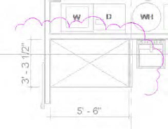
If you want to place a revision, open a view in which changes to the project have occurred and use the Revision Cloud tool found in the Detail panel on the Annotate tab. Use the familiar sketching tools from the Draw panel in the contextual tab of the ribbon to generate a cloud around the area you are calling out as a revision. The tool automatically starts with the Box command, allowing you to draw a box around your revision. If you’d like something more fluid, you can switch to the Line tool on the Draw panel. Lines are automatically created that make a cloud (or series of arcs), as shown in Figure 19.4. The size of the arcs will be determined by the Arc Length setting found in the Sheet Issues/Revisions dialog box we described in the previous section. When you finish creating the cloud, click the Finish Sketch button (the green check mark) in the contextual tab of the ribbon. Note that the Revision cloud tool doesn’t require you to form a closed loop—you can finish the sketch at any point.
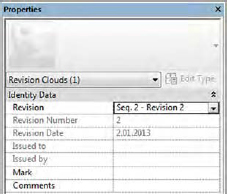
By default, each new revision cloud will be assigned to the last revision in the Sheet Issues/Revisions dialog box. If you need to change the revision to which a cloud is assigned, select the cloud and use the Properties palette to modify its revision number (Figure 19.5).
Figure 19.5 The revision cloud’s issue assignment can be changed in the Properties palette.
As soon as you have placed a revision cloud on a sheet, any revision schedules placed in your title block will update to include the revision number, description, and the date you assigned in the Sheet Issues/Revisions dialog box earlier (Figure 19.6).
Figure 19.6 The updated title block with the revision information
Like other objects, the graphics for revision clouds are controlled from the Object Styles dialog box, found in the Settings panel on the Manage tab. Settings for revisions are located on the Annotation Objects tab. The default setting for the line thickness is 1. We recommend that you increase the default thickness for revisions in your project template to more clearly illustrate and communicate your design modifications.
Tagging a Revision Cloud
Revision clouds can be tagged like many other elements. Similar to other tags, revision tags are intelligent and designed to report the revision number or letter that has been assigned to the revision cloud. To place a revision tag, use the Tag By Category tool in the Tag panel on the Annotate tab.
If a tag for revisions is not in your template, you will be warned that no such tag exists in your project. To continue, simply load a revision tag. The default tag is named Revision Tag.rfa and is located in the Annotations folder of the family library within a standard installation.
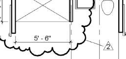
Once you have a tag loaded, you are ready to tag revision clouds. Hover the cursor over a revision cloud and click to place the tag. You will see a preview of the tag prior to placing it (Figure 19.7). Once the tag is placed, you can drag it around the cloud to reposition it and turn the leader on and off. With or without a leader, the revision tag will stay associated with the cloud.
You can choose to use a leader line between the tag and the cloud, depending on your preference or your office standards. In many cases, the tag just needs to be near the cloud and a leader is not necessary. Disable the leader by selecting the tag and clearing the Leader option in the Options bar. It’s good to note here that if your firm’s standards are to hide the cloud and you have the leader activated, you’ll see the revision tag plus the leader but no cloud since the leader and tag are connected.
Using Digital Markups
Both Autodesk® A360 (www.autodesk360.com) and Autodesk® Design Review offer an efficient way to view and mark up 2D digital documents and 3D models. This workflow is different from revisions and is geared more toward informal design review rather than the management of sheet issues. For example, if your drawings must be reviewed for quality control and overall comments by a senior designer who might not be familiar with Revit software, this tool can streamline the process. The senior designer, consultant, or any other third party can make comments and review changes directly in the digital file and return them to the Revit Architecture user who needs to modify the original model.
In this section, we’re going to focus on the use of Design Review for DWF markups. Both applications are capable of this workflow. Think of the A360 tool as an online version of the DWF markup tool. It additionally has many powerful collaboration tools to help the overall project process—markups are only a portion of what the tool does. Feel free to explore A360 to see the full effect it can have on team collaboration.
Using Design Review, you can view files in DWFx or DWF format. If you export sheets to DWFx and the markups are linked back into Revit, the markups will be automatically placed on the corresponding sheet. So there is no need on your part for any sort of alignment or placement of the revisions.
Design Review is a free tool that you can download from the Autodesk website: usa.autodesk.com/design-review. Once it’s installed, you can open and mark up any DWFx or DWF file produced by any Autodesk or other CAD/BIM software package.
Publishing to Design Review
There are two ways to share your model using Design Review: as 2D drawings or as a 3D model. If you publish to 3D, you create a single 3D representation of your model that can be orbited, control visibility of element catagories, and be queried for the properties of any of the elements. Publishing to 2D can create either a single view or a whole collection of interconnected views and sheets packaged as one file. You can even combine 2D views and a 3D model in one DWFx file.
EXPORTING DWFX FILES
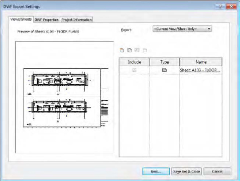
You can export to DWFx from any view, except a schedule. To export your views or sheets, select the Application menu and choose Export ➢ DWF/DWFx. The DWF Export Settings dialog box (Figure 19.8) will open. Here you can choose views/sheets to export in addition to specifying how the results will be published.
Open Sheet A101 from the sheet list in the Project Browser. Click the Application menu and select Export ➢ DWF/DWFx to open the dialog box shown in Figure 19.8.
Click the New Set icon at the top of the list of views and name the set MASTERING SHEETS.
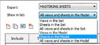
Once you create the set, you will see a new drop-down list appear in the dialog box; you can use it to control which views are displayed in the view list (Figure 19.9).
From the Show In List drop-down, select Sheets In The Model, and then select sheets A101 and A102.
These sheets will be added to the set to be published.
You can sort the list of views by any of the columns by clicking a column header. Try this by clicking the Name header.
To check the export size, select the DWF Properties tab and click the Print Setup button. In the resulting dialog box, you can set explicit sizes for your export. Click the option Use Sheet Size to automatically detect sheet sizes based on the title blocks you are using in the project.
This dialog box mirrors the one used for printing.
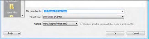
Click Next and specify the name of the file and a location in which to save it. Make sure you check the box to combine all sheets into a single DWFx file (see Figure 19.10).
Open the published DWFx file in Autodesk Design Review. Choose the Markup & Measure tab, and then add a few comments and markups on the A101 sheet.
Figure 19.9 The Show In List drop-down is available only with a view set.
Figure 19.10 Manual file naming is available when you combine views for publishing.
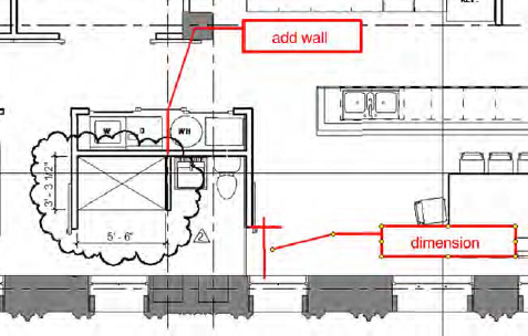
Using the Shapes and Draw tools on this tab, you can add clouds, arrows, and text to insert your comments or changes into the drawings. This can be done in a variety of colors and line weights to give them extra visibility on the page. Once all your changes are created, save the file and it will retain all your changes. Figure 19.11 shows an example of a markup.
Once you’ve added markups to the DWFx file, save the file and close Design Review. You can then link the marked-up DWFx file back into the RVT project file. Continue to use the sample file from the previous exercise. You can also download the file c19-Sample-MarkedUp.dwfx from this book’s web page. This file already contains some markups to use in the following exercise. Perform these steps to import the marked-up file into the project file:
On the Insert tab, choose DWF Markup from the Link panel and then select the DWFx file you saved in the previous exercise.
This is a simple import dialog box. There are no settings in the window.
When you select a DWFx file, only the markups will be shown—not the entire DWFx file. If there are no markups in the file, nothing will be visible in Revit.
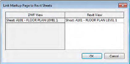
In the next dialog box (Figure 19.12), you will see the views in the DWFx file that contain markups and the sheets in the Revit project to which they will coordinate. You can insert all the markups or only specific sheets. Select the sheets you’d like to import; be sure to select A101, and then click OK.
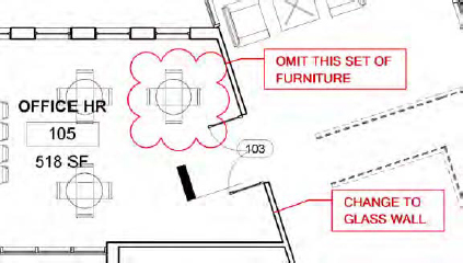
Open sheet A101 from the Project Browser, and you will see the markup as an overlay in the same location where it was created in Design Review (Figure 19.13).
Markups can be linked only to sheets. If you export a view and mark it up, you will not be able to link that view back into the model. Also, none of the other linework from the DWF will link into the model—any of the building geometry, backgrounds, sheet content, and so on. The only thing that will be visible in Revit is content created with the DWF Markup tool.
You cannot move or delete linked DWF markups—they appear with a pin if selected; however, you can do a number of things to graphically indicate that you’ve reviewed a markup:
Change its graphic appearance. Let’s say you have 20 redline markups on your sheet. You need to keep track of which ones you’ve picked up. One way to do this is to graphically override each markup as you make the requested modifications. Select the markup, right-click, choose View ➢ By Element, and click Override Graphics. Choose a color to indicate “done.” Yellow works well because it suggests a highlight marker.
Hide it. This approach is similar to the graphic override, but you hide the markup altogether. Select the markup, right-click, and choose Hide In View ➢ Element.
Remove it. You can remove markups by choosing Manage Links from the Manage tab. In the Manage Links dialog box, select the DWF Markups tab, select the markup, and click the Remove button. This removes all markups associated with the link.
Figure 19.12 Sheets with associated markups are shown.
Figure 19.13 The marked-up sheet linked into Revit
Another way you can interact with a linked DWF file is by modifying the status or appending comments to each markup. You can access these features in the Properties palette when you select a markup, as follows:
In the A101 sheet view, select one of the markups you created and go to the Properties palette.
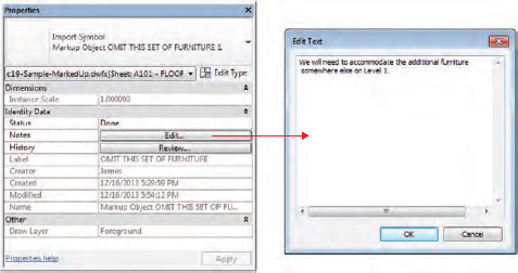
Change the Status drop-down list to Done and then click the Edit button in the Notes field. In the Edit Text dialog box, enter some text related to the completion of the design modification requested in the markup (Figure 19.14).
Click the Apply button at the bottom of the Properties palette or move the mouse pointer out of the Properties palette.
Switch to the Insert tab in the ribbon, and from the Link panel choose Manage Links. Select the DWF Markups tab.
Select the row containing the DWFx file you linked in the previous steps, and then click the Save Markups button at the bottom left of the dialog box.
There is no alert or notification that the save process has completed, so just wait a few seconds.
Click OK to close the Manage Links dialog box.
Open the DWFx file again in Design Review, and you will see that the status of the markups has been updated.
Figure 19.14 Modifying the properties of the markup
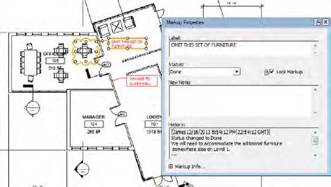
The comments you added to them can be seen in the Markup Properties palette (Figure 19.15).
Figure 19.15 Modifying the properties of the markup
Using the DWFx file format along with the integrated tools within Revit, you have closed a communication and coordination loop that has traditionally been an area of difficulty. This workflow also benefits larger project teams because you don’t have to manage a central pile of drawing markups that need to be shared or distributed among several teammates. All the staff working on a project will have access to the same linked DWF markups.
Modeling for Construction
Now that we have reviewed some basic functionality a design team might use in the construction phase, let’s take a look at how a builder (contractor, subcontractor, or construction manager) might use Revit in the industry today.
Revit is often referred to as a design application; however, contractors are using the software more frequently as both a model-authoring and project-analysis tool. Although builders use BIM tools to obtain different results than design professionals do, many of the processes and functions are the same; they are merely applied in particular ways according to the needs of the various users.
Functionality introduced in Revit Architecture 2012 supports a more interactive and flexible approach to construction modeling. The first addition was the ability to create parts, which are individual subsets of more complex layered elements such as walls and floors. The other addition allowed you to generate assemblies, which are segregated subsets of the project model with their own associated views, annotations, and sheets. These tools are used to take large elements and break them down into smaller components as they’d be used on the job site. As an example, in an architectural model, a cast-in-place concrete floor would be a single element for the entire floor plate. In practice, the contractor would never pour the floor that way. The concrete would be poured in a series of pads, and the contractor would have to divide the slab into those series of pours for their schedule. The potential to minimize data loss between the design and construction stakeholders of a project can start to change how we approach collaboration and delivery of our buildings.
Creating Parts
Parts are designed to aid the user in subdividing larger model elements into smaller components for construction planning. Each part maintains a persistent relationship with the elements from which it was derived, and it can be subdivided into smaller parts if necessary. Parts can be generated from walls, floors, ceilings, and roofs, as long as they are of consistent thickness. They also have their own properties, such as volume, area, and height; as such, they can be scheduled independently of their original elements.
While it is likely that designers will use parts to customize architectural elements, we are going to discuss only the workflow intended for the builder. To get started with the basic workflow for creating and dividing parts, follow these steps:
Open the file c19-Parts-Start.rvt or c19-Parts-Metric-Start.rvt, which you can download from this book’s web page.
Activate the Default 3D view if it isn’t already open.
Notice that each of the wall, floor, ceiling, and roof elements in this sample model is composed of one object. A section box has been activated in this view that is exposing the layers within each element (Figure 19.16).
Select the floor at Level 2. On the Create panel in the contextual tab of the ribbon, click the Create Parts button.
Notice that the original object has been visually replaced in the current view by the parts representing each layer of the floor assembly. It is still in the project model—it has not been deleted.
There is a new view property in the Properties palette named Parts Visibility whose default value is Show Parts. This means that if parts have been created for any object, they will be displayed instead of the original. This property can also be set to Show Original or Show Both.
In the Project Browser, right-click the Default 3D view and choose Duplicate View and then Duplicate. Rename the copy of the view Original Model.
Activate the view named Original Model. From the Properties palette, find the Parts Visibility parameter and change it to Show Original.
In the Project Browser, rename the {3D} view to Parts Model.
Activate the Parts Model view, and repeat the process of creating parts for the wall, the ceilings, and the roof in the sample model. Simply select each of these elements and choose the Parts tool from the context menu as before.
In the previous exercise, you created an alternative way to view your model that begins to explore constructability. Without additional modification, you can start to interact with these individual components by examining their properties or even hiding them or overriding their graphic display.
Modifying Parts
In addition to creating parts from original model elements, you can divide these parts into smaller ones. You can even change the phasing properties at the part level and use grips to modify the extents of the parts. Let’s begin with an exercise to divide some parts using planes and sketched lines:
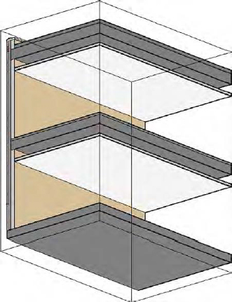
Go back to the Parts Model view and select the top part of the roof at the Roof level.
This will be the layer representing insulation.
From the Part panel in the contextual ribbon, click Divide Parts.
You will enter Sketch mode, where you can either select intersecting datum or draw your own dividing lines.
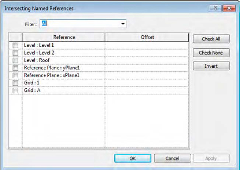
Click the Intersecting References button in the contextual ribbon. You are presented with the Intersecting Named References dialog box (Figure 19.17). From the Filter drop-down list, select All and notice that you can choose from levels, grids, and named reference planes.
If a reference plane has not been named, it will not appear in this list.
Check the boxes for the two reference planes named xPlane1 and yPlane1. Click OK to close the dialog box. You’ll see two green datum objects highlight in the model.
Click the green check mark in the contextual ribbon to finish Edit mode.
After you complete the process for dividing the part, notice that the part has now become four separate pieces. To experiment with how the parts maintain their relationship to the original object as well as the intersecting reference planes, go to the Level 1 floor plan and move the reference planes around, but try to keep them within the boundary of the sample floor. When you return to the 3D view, you will see that the divisions stay synchronized with the reference planes.
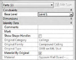
Activate the ceiling plan for Level 1. In the Properties palette for the view, change Parts Visibility to Show Parts. Select the Gypsum Wall Board part on the bottom of the ceiling below the Level 2 floor.
Graphically, this will look like you’re selecting the entire ceiling because it will all highlight blue.
You can make sure you have the correct part selected by examining the Properties palette. The category filter at the top should display Parts (1) and the Material parameter should indicate Gypsum Wall Board – Ceiling (Figure 19.18).
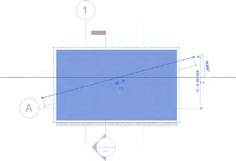
Click the Divide Parts button in the contextual ribbon, and then click the Edit Sketch button to activate Sketch mode. Draw a diagonal line across the part from left to right, as shown in Figure 19.19.
If you need to sketch lines to divide parts, the lines do not have to be in closed loops, but they must intersect the boundaries of the part. Keep in mind that if the original element is edited so that its boundaries extend beyond any sketched part divisions, the part divisions will be deleted.
Click the green check mark in the contextual ribbon to finish the sketch, and then click it again to finish the part-dividing mode.
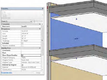
Activate the Parts Model view, and orbit the model so you can select the inside face of the wall. Select the part of the wall that would represent the gypsum wall board at the interior face of Level 2.
From the Properties palette, find the Show Shape Handles parameter and check the box. You will see triangular shape handles on all four sides of the part, as shown in Figure 19.20. Drag the top shape handle down to indicate that the gypsum wall board is not to be installed to the full height of the wall assembly.
Figure 19.17 You can use a datum as one way to divide parts.
Figure 19.18 Verify your selection of the gypsum ceiling by making sure you have (1) part selected and the material is Gypsum Wall Board.
Figure 19.20 Use the Properties palette to enable shape handles for parts.
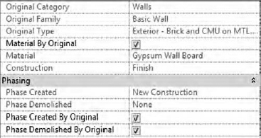
There are several other ways you can interact with parts in your project model. Select any of the parts and observe the Properties palette. You will see that you can override each part’s material, phase created, and phase demolished (Figure 19.21).
Figure 19.21 Some part properties can be overridden.
DIVIDING PARTS WITH A GAP
In the previous exercise, you learned how to divide parts using datum objects and simple sketches. You also have the ability to divide parts with a defined gap as well as with a custom profile. Let’s explore these options with another exercise:
Continue to work with the sample file c19-Parts-Start.rvt or c19-Parts-Metric-Start.rvt from the previous exercise. Activate the Parts Model 3D view and orbit the model to view the exterior face of the wall.
Select the main part of the exterior wall face that has the material assignment Concrete, Precast. Click the Divide Parts tool in the contextual ribbon.
In the Properties palette, set the Divider Gap parameter to 1" (25 mm).
Click the Intersecting References tool in the ribbon, set the filter to All, and then select Level 2, Reference Plane: yPlane1, and Grid: 1. Click OK to close the dialog box.
Click the green check mark in the ribbon to finish Divide Parts mode, and the panel will be divided with a continuous gap, as shown in Figure 19.22.
In addition to simple gaps, parts can be divided with a custom profile. A family template called Division Profile.rft (Metric Division Profile.rft) is available in the default family template library. This profile family is similar to other profiles except that the completed sketch in the family does not need to be a closed loop. That said, the sketch must extend completely between the two reference planes associated with the Width parameter in the template.
A number of division profiles are loaded in the default architectural project template. You can find these in the Project Browser under Families ➢ Division Profiles. To examine how any of these are created, right-click Tapered Notch and select Edit from the context menu.
Let’s explore how you can edit an existing division and apply a custom profile to the gap. Follow these steps:
Continue to work with the project file c19-Parts-Start.rvt or c19-Parts-Metric-Start.rvt from the previous exercise. Activate the Parts Model 3D view, and orbit the model to view the exterior face of the wall.
Select any one of the divided parts of the main precast concrete portion of the wall. Once a part has been divided, you won’t need to select all the parts to edit the division—select just one. From the contextual ribbon, click Edit Division.
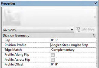
In the Properties palette, change the Division Profile parameter to Angled Step: Angled Step. Once you select a profile type, additional parameters are available in the Properties palette. Set the Edge Match parameter to Complementary (Figure 19.23).
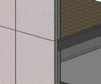
Click the green check mark in the ribbon to finish the division edits, and you will see that the updated profiles are applied to all edges of the divided parts (Figure 19.24).
To explore different functionality with division profiles, repeat steps 2 through 4, but select the profile Notch and set the Edge Match parameter to Mirrored. Observe the change in behavior using a different matching property.
When you apply a custom profile to a division of parts, the profile is applied to all divisions. If you need to assign different profiles to different divisions, each of those unique divisions must be applied separately. Let’s try this approach by continuing the exercise.
In the Parts Model view, select any of the precast concrete parts you generated earlier in this exercise. Click Edit Division in the contextual ribbon.
Click the Intersecting References button in the ribbon, and in the Intersecting Named References dialog box, set the Filter drop-down to All, and then deselect Reference Plane: yPlane1.
Click OK to close the dialog box, and then click the green check mark in the ribbon to finish editing the division.
While pressing the Ctrl key, select the two larger precast concrete panels to the right side of the wall. Click the Divide Parts button in the ribbon.
Click the Intersecting References button in the ribbon, set the Filter drop-down to All, and then select Reference Plane: yPlane1. Click OK to close the dialog box.
In the Properties palette, set the Divider Gap parameter to 0"–1" (25 mm). Click the green check mark in the ribbon to finish editing the division.
Figure 19.23 Assigning a division profile to a part
Figure 19.24 Parts divided with a division profile
You will now see that the custom profile was maintained for the other part divisions, but the rightmost vertical division has only a simple gap.
MERGING PARTS
Parts can be merged to form larger, more contiguous geometry; however, the parts to be merged must have the same material and the same creation and demolition phases, and the merged geometry must consist of a single connected component. Parts with gaps assigned to the divisions will not be merged.
To merge parts, press the Ctrl key while selecting multiple parts. In the contextual ribbon, click Merge Parts. Once parts have been merged, you can always edit them in the future. To edit merged parts, select the part and then select Edit Merged from the contextual ribbon.
EXCLUDING PARTS
Parts can also be excluded from a model to support more detailed construction conditions. To exclude a part, select the part and click Exclude Parts from the Exclude panel of the contextual ribbon. Excluded parts will not appear in any schedules; however, they are easily restored. To restore an excluded part, hover over the area with your mouse pointer where the part was excluded. You will be able to select the excluded part, but it will be indicated with a special icon. Click the icon on the excluded part or click Restore Parts in the contextual ribbon.
Scheduling Parts
Another valuable aspect of using parts is the ability to schedule them—essentially a cleaner way to generate material takeoffs. You can create a parts schedule in the same manner as you would for other object categories. On the View tab, click Schedules ➢ Schedule/Quantities, and choose the Parts category.
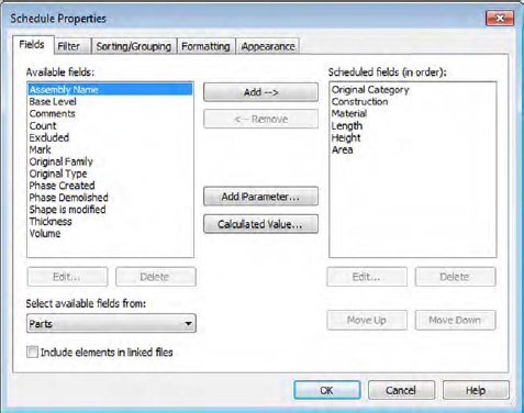
Select the Fields tab of the Schedule Properties dialog box, and you will see the available fields (Figure 19.25). With a part schedule, you can report the original category of the object along with the part material and the usual geometric information.
Figure 19.25 A part schedule has access to some unique fields for reporting.
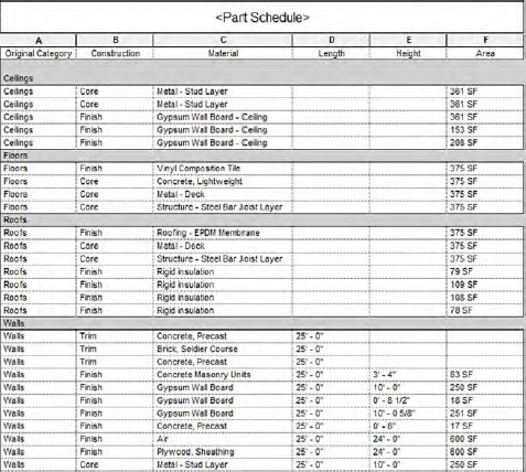
There is also a field named Construction that indicates whether the part was derived from a Core layer or a Finish layer. This field can then be used as a filter and/or sorting criterion in your schedule. An example illustrating the results of a part schedule is shown in Figure 19.26.
Figure 19.26 An example of a completed part schedule
Creating Assemblies
An assembly organizes related elements within your project. The feature is designed to help users track and schedule a collection of elements as a single entity. In the case of precast concrete, for example, a column made of multiple families, including reinforcing bars, mounting hardware, and corbels, can be collected into a single assembly.
As you identify objects to be included in an assembly, you can also choose from a variety of views in which to document the element in isolation from the rest of the project model. A collection of assembly views can be thought of as shop drawings. Let’s take a look at the workflow for creating an assembly.
In the following exercise, you can use any sample model to illustrate the process of creating assemblies:
In any view of your project, select a few model elements. Try to pick a few that are relatively close to each other.
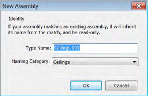
From the contextual tab in the ribbon, click Create Assembly. You will be prompted to name the new assembly (Figure 19.27).
If you selected objects of different categories such as a wall and a ceiling, you have the opportunity to select which category the assembly will inherit. Choosing one category or the other does not seem to have an effect on the functionality beyond the organization that is exposed to the user.
After you have created an assembly, you can create a series of views that are dedicated to that assembly. In other words, you will see only the elements included in the assembly within these views. In addition to plans, sections, and 3D views, you can generate parts lists and quantity takeoffs for an assembly.
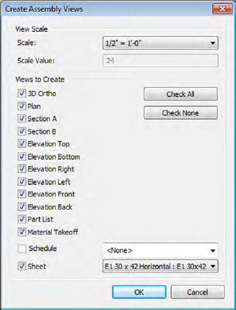
To generate assembly views, select an assembly in any view and select Create Views from the Assembly panel in the contextual tab of the ribbon. You are prompted with a dialog box in which you choose the views assigned to the assembly (Figure 19.28).
Figure 19.28 Select views to be created with the assembly.
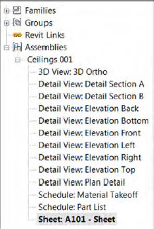
After you click OK, you will find the assembly views at the bottom of the Project Browser. Under the Assembly grouping, you will find each assembly listed with all the associated views (Figure 19.29).
Figure 19.29 Assembly views are found at the bottom of the Project Browser.
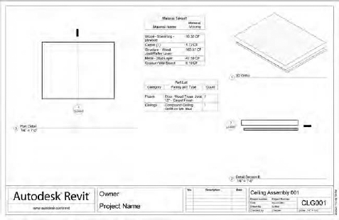
Although sections are automatically placed for the included elements, the individual views are not placed on the assembly sheet. To do this, activate the sheet within an assembly and then drag and drop the views onto the sheet. Note that assembly views can be used on nonassembly sheets and regular views can be placed on an assembly sheet. An example of views compiled into an assembly sheet is shown in Figure 19.30.
Figure 19.30 An example of a simple assembly sheet
The Bottom Line
Add revisions to your project. You need the ability to track changes in your design after sheets have been issued. Adding revisions to a drawing is an inevitable part of your workflow.
Master It How do you indicate revisions on a drawing sheet?
Use digital markups. DWFs provide a lightweight means to digitally transfer and mark up multiple sheets in a document set.
Master It Explain the workflow using DWF markups.
Model for construction. Parts and assemblies allow a model element to be broken down into smaller parts. These subelements can be used in more detailed ways for the construction process while still maintaining their association with the original element.
Master It Describe the method for breaking down a design-based model assembly into its individual components.


 Creating Assembly Views