
Chapter 3: All about Bootloaders
The bootloader is the second element of embedded Linux. It is the part that starts the system and loads the operating system kernel. In this chapter, we will look at the role of the bootloader and, in particular, how it passes control from itself to the kernel using a data structure called a device tree, also known as a flattened device tree or FDT. I will cover the basics of device trees, as this will help you follow the connections described in a device tree and relate it to real hardware.
I will look at the popular open source bootloader known as U-Boot and show you how to use it to boot a target device, as well as how to customize it so that it can run on a new device by using the BeagleBone Black as an example.
In this chapter, we will cover the following topics:
- What does a bootloader do?
- The boot sequence
- Moving from the bootloader to a kernel
- Introducing device trees
- U-Boot
Let's get started!
Technical requirements
To follow along with the examples in this chapter, make sure you have the following:
- A Linux-based host system with device-tree-compiler, git, make, patch, and u-boot-tools or their equivalents installed.
- The Crosstool-NG toolchain for BeagleBone Black from Chapter 2, Learning
About Toolchains. - A microSD card reader and card.
- A USB to TTL 3.3V serial cable
- BeagleBone Black
- A 5V 1A DC power supply
All the code that will be used in this chapter can be found in the Chapter03 folder of this book's GitHub repository: https://github.com/PacktPublishing/Mastering-Embedded-Linux-Programming-Third-Edition.
What does a bootloader do?
In an embedded Linux system, the bootloader has two main jobs: to initialize the system to a basic level and to load the kernel. In fact, the first job is somewhat subsidiary to the second, in that it is only necessary to get as much of the system working as is needed to load the kernel.
When the first lines of the bootloader code are executed, following a power-on or a reset, the system is in a very minimal state. The DRAM controller is not set up, so the main memory is not accessible. Likewise, other interfaces are not configured, so storage that's accessed via NAND flash controllers, MMC controllers, and so on is unavailable. Typically, the only resources that are operational at the beginning are a single CPU core, some on-chip static memory, and the boot ROM.
System bootstrap consists of several phases of code, each bringing more of the system into operation. The final act of the bootloader is to load the kernel into RAM and create an execution environment for it. The details of the interface between the bootloader and the kernel are architecture-specific, but in each case, it has to do two things. First, the bootloader has to pass a pointer to a structure containing information about the hardware configuration. Second, it has to pass a pointer to the kernel command line.
The kernel command line is a text string that controls the behavior of Linux. Once the kernel has begun executing, the bootloader is no longer needed and all the memory it was using can be reclaimed.
A subsidiary job of the bootloader is to provide a maintenance mode for updating boot configurations, loading new boot images into memory, and, maybe, running diagnostics. This is usually controlled by a simple command-line user interface, commonly over a serial console.
The boot sequence
In simpler times, some years ago, it was only necessary to place the bootloader in non-volatile memory at the reset vector of the processor. NOR flash memory was common at that time and, since it can be mapped directly into the address space, it was the ideal method of storage. The following diagram shows such a configuration, with the Reset vector at 0xfffffffc at the top end of an area of flash memory. The bootloader is linked so that there is a jump instruction at that location that points to the start of the bootloader code:

Figure 3.1 – NOR flash
From that point on, the bootloader code running in NOR flash memory can initialize the DRAM controller so that the main memory – the DRAM – becomes available and then copies itself into the DRAM. Once fully operational, the bootloader can load the kernel from flash memory into DRAM and transfer control to it.
However, once you move away from a simple linearly addressable storage medium such as NOR flash, the boot sequence becomes a complex, multi-stage procedure. The details are very specific to each SoC, but they generally follow each of the following phases.
Phase 1 – ROM code
In the absence of reliable external memory, the code that runs immediately after a
reset or power-on has to be stored on-chip in the SoC; this is known as ROM code. It is loaded into the chip when it is manufactured, and hence the ROM code is proprietary and cannot be replaced by an open source equivalent. Usually, it does not include code to initialize the memory controller, since DRAM configurations are highly device-specific, and so it can only use Static Random Access Memory (SRAM), which does not require a memory controller.
Most embedded SoC designs have a small amount of SRAM on-chip, varying in size from as little as 4 KB to several hundred KB:

Figure 3.2 – Phase 1 – ROM code
The ROM code is capable of loading a small chunk of code from one of several pre-programmed locations into the SRAM. As an example, TI OMAP and Sitara chips try to load code from the first few pages of NAND flash memory, or from flash memory connected through a Serial Peripheral Interface (SPI), or from the first sectors of an MMC device (which could be an eMMC chip or an SD card), or from a file named MLO on the first partition of an MMC device. If it's reading from all these memory devices fails, then it tries reading a byte stream from Ethernet, USB, or UART; the latter is provided mainly as a means of loading code into flash memory during production, rather than for use in normal operation. Most embedded SoCs have ROM code that works in a similar way. In SoCs, where the SRAM is not large enough to load a full bootloader such as U-Boot, there has to be an intermediate loader called the secondary program loader (SPL).
At the end of the ROM code phase, the SPL is present in the SRAM and the ROM code jumps to the beginning of that code.
Phase 2 – secondary program loader
The SPL must set up the memory controller and other essential parts of the system in preparation for loading the Tertiary Program Loader (TPL) into DRAM. The functionality of the SPL is limited by the size of the SRAM. It can read a program from a list of storage devices, as can the ROM code, once again using pre-programmed offsets from the start of a flash device. If the SPL has filesystem drivers built in to it, it can read well-known filenames, such as u-boot.img, from a disk partition. The SPL usually doesn't allow for any user interaction, but it may print version information and progress messages, which you can see on the console. The following diagram explains the phase 2 architecture:

Figure 3.3 – Phase 2 – SPL
The preceding diagram shows the jump from ROM code to SPL. As the SPL executes within SRAM, it loads the TPL into DRAM. At the end of the second phase, the TPL is present in DRAM, and the SPL can make a jump to that area.
The SPL may be open source, as is the case with the TI x-loader and Atmel AT91Bootstrap, but it is quite common for it to contain proprietary code that is supplied by the manufacturer as a binary blob.
Phase 3 – TPL
At this point, we are running a full bootloader, such as U-Boot, which we will learn about a bit later in this chapter. Usually, there is a simple command-line user interface that lets you perform maintenance tasks, such as loading new boot and kernel images into flash storage, and loading and booting a kernel, and there is a way to load the kernel automatically without user intervention.
The following diagram explains the phase 3 architecture:
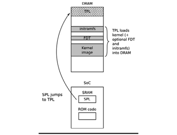
Figure 3.4 – Phase 3 – TPL
The preceding diagram shows the jump from SPL in SRAM to TPL in DRAM. As the TPL executes, it loads the kernel into DRAM. We also have the choice of appending an FDT and/or initial RAM disk to the image in DRAM if we want. Either way, at the end of the third phase, there is a kernel in memory, waiting to be started.
Embedded bootloaders usually disappear from memory once the kernel is running and have no further part in the operation of the system. Before that happens, the TPL needs to hand off control of the boot process to the kernel.
Moving from the bootloader to a kernel
When the bootloader passes control to the kernel, it has to pass some basic information, which includes the following:
- The machine number, which is used on PowerPC and Arm platforms without support for a device tree, to identify the type of the SoC.
- Basic details of the hardware that's been detected so far, including (at the very least) the size and location of the physical RAM and the CPU's clock speed.
- The kernel command line.
- Optionally, the location and size of a device tree binary.
- Optionally, the location and size of an initial RAM disk, called the initial RAM file system (initramfs).
The kernel command line is a plain ASCII string that controls the behavior of Linux by giving, for example, the name of the device that contains the root filesystem. We will look at the details of this in the next chapter. It is common to provide the root filesystem as a RAM disk, in which case it is the responsibility of the bootloader to load the RAM disk image into memory. We will cover how create initial RAM disks in Chapter 5, Building a Root Filesystem.
The way this information is passed is dependent on the architecture and has changed in recent years. For instance, with PowerPC, the bootloader simply used to pass a pointer to a board information structure, whereas with Arm, it passed a pointer to a list of A tags. There is a good description of the format of A tags in the kernel source in Documentation/arm/Booting.
In both cases, the amount of information that was passed was very limited, leaving the bulk of it to be discovered at runtime or hard-coded into the kernel as platform data. The widespread use of platform data meant that each board had to have a kernel configured and modified for that platform. A better way was needed, and that way is the device tree. In the Arm world, the move away from A tags began in earnest in February 2013 with the release of Linux 3.8. Today, almost all Arm systems use device tree to gather information about the specifics of the hardware platform, allowing a single kernel binary to run on a wide range of those platforms.
Now that we've learned what a bootloader does, what the stages of the boot sequence are, and how it passes control to the kernel, let's learn how to configure a bootloader so that it runs on popular embedded SoCs.
Introducing device trees
If you are working with Arm or PowerPC SoCs, you are almost certainly going to encounter device trees at some point. This section aims to give you a quick overview of what they are and how they work. We will revisit the topic of device trees repeatedly throughout the course of this book.
A device tree is a flexible way of defining the hardware components of a computer system. Bear in mind that a device tree is just static data, not executable code. Usually, the device tree is loaded by the bootloader and passed to the kernel, although it is possible to bundle the device tree with the kernel image itself to cater for bootloaders that are not capable of loading them separately.
The format is derived from a Sun Microsystems bootloader known as OpenBoot, which was formalized as the Open Firmware specification, which is IEEE standard IEEE1275-1994. It was used in PowerPC-based Macintosh computers and so was a logical choice for the PowerPC Linux port. Since then, it has been adopted at a large scale by the many Arm Linux implementations and, to a lesser extent, by MIPS, MicroBlaze, ARC, and other architectures.
I would recommend visiting https://www.devicetree.org for more information.
Device tree basics
The Linux kernel contains a large number of device tree source files in arch/$ARCH/boot/dts, and this is a good starting point for learning about device trees. There are also a smaller number of sources in the U-boot source code in arch/$ARCH/dts. If you acquired your hardware from a third party, the dts file forms part of the board support package, so you should expect to receive one along with the other source files.
The device tree represents a computer system as a collection of components joined together in a hierarchy, such as a tree. The device tree begins with a root node, represented by a forward slash, /, which contains subsequent nodes representing the hardware of the system. Each node has a name and contains a number of properties in the form name = "value". Here is a simple example:
/dts-v1/;
/{
model = "TI AM335x BeagleBone";
compatible = "ti,am33xx";
#address-cells = <1>;
#size-cells = <1>;
cpus {
#address-cells = <1>;
#size-cells = <0>;
cpu@0 {
compatible = "arm,cortex-a8";
device_type = "cpu";
reg = <0>;
};
};
memory@0x80000000 {
device_type = "memory";
reg = <0x80000000 0x20000000>; /* 512 MB */
};
};
Here, we have a root node that contains a cpus node and a memory node. The cpus node contains a single CPU node named cpu@0. The names of these nodes often include an @, followed by an address that distinguishes the node from other nodes of the same type. @ is required if the node has a reg property.
Both the root and CPU nodes have a compatible property. The Linux kernel uses this property to find a matching device driver by comparing it with the strings that are exported by each device driver in a of_device_id structure (more on this in Chapter 11, Interfacing with Device Drivers).
Important Note
It is a convention that the value of the compatible property is composed of a manufacturer name and a component name, to reduce confusion between similar devices made by different manufacturers; hence, ti,am33xx and arm,cortex-a8. It is also quite common to have more than one value for the compatible property where there is more than one driver that can handle this device. They are listed with the most suitable mentioned first.
The CPU node and the memory node have a device_type property, which describes the class of device. The node name is often derived from device_type.
The reg property
The memory and cpu nodes shown earlier have a reg property, which refers to a range of units in a register space. A reg property consists of two values representing the real physical address and the size (length) of the range. Both are written as zero or more 32-bit integers, called cells. Hence, the previous memory node refers to a single bank of memory that begins at 0x80000000 and is 0x20000000 bytes long.
Understanding reg properties becomes more complex when the address or size values cannot be represented in 32 bits. For example, on a device with 64-bit addressing, you need two cells for each:
/{
#address-cells = <2>;
#size-cells = <2>;
memory@80000000 {
device_type = "memory";
reg = <0x00000000 0x80000000 0 0x80000000>;
};
};
The information about the number of cells required is held in the #address-cells and #size_cells properties in an ancestor node. In other words, to understand a reg property, you have to look backward down the node hierarchy until you find #address-cells and #size_cells. If there are none, the default values are 1 for each – but it is bad practice for device tree writers to depend on defaults.
Now, let's return to the cpu and cpus nodes. CPUs have addresses as well; in a quad core device, they might be addressed as 0, 1, 2, and 3. That can be thought of as a one-dimensional array without any depth, so the size is zero. Therefore, you can see that we have #address-cells = <1> and #size-cells = <0> in the cpus node, and in the child node, cpu@0, we assign a single value to the reg property, reg = <0>.
Labels and interrupts
The structure of the device tree we've described so far assumes that there is a single hierarchy of components, whereas there are, in fact, several. As well as the obvious data connection between a component and other parts of the system, it might also be connected to an interrupt controller, to a clock source, and to a voltage regulator. To express these connections, we can add a label to a node and reference the label from other nodes. These labels are sometimes referred to as phandles, because when the device tree is compiled, nodes with a reference from another node are assigned a unique numerical value in a property called phandle. You can see them if you decompile the device tree binary.
Take, as an example, a system containing an LCD controller that can generate interrupts and an interrupt-controller:
/dts-v1/;
{
intc: interrupt-controller@48200000 {
compatible = "ti,am33xx-intc";
interrupt-controller;
#interrupt-cells = <1>;
reg = <0x48200000 0x1000>;
};
lcdc: lcdc@4830e000 {
compatible = "ti,am33xx-tilcdc";
reg = <0x4830e000 0x1000>;
interrupt-parent = <&intc>;
interrupts = <36>;
ti,hwmods = "lcdc";
status = "disabled";
};
};
Here, we have the interrupt-controller@48200000 node with a label of intc. The interrupt-controller property identifies it as an interrupt controller. Like all interrupt controllers, it has an #interrupt-cells property, which tells us how many cells are needed to represent an interrupt source. In this case, there is only one that represents the interrupt request (IRQ) number. Other interrupt controllers may use additional cells to characterize the interrupt; for example, to indicate whether it is edge or level triggered. The number of interrupt cells and their meanings is described in the bindings for each interrupt controller. The device tree bindings can be found in the Linux kernel source, in the Documentation/devicetree/bindings/ directory.
Looking at the lcdc@4830e000 node, it has an interrupt-parent property, which references the interrupt controller it is connected to, using the label. It also has an interrupts property, which is 36 in this case. Note that this node has its own label, lcdc, which is used elsewhere: any node can have a label.
Device tree include files
A lot of hardware is common between SoCs of the same family and between boards using the same SoC. This is reflected in the device tree by splitting out common sections into include files, usually with the .dtsi extension. The Open Firmware standard defines /include/ as the mechanism to be used, as in this snippet from vexpress-v2p-ca9.dts:
/include/ "vexpress-v2m.dtsi"
Look through the .dts files in the kernel, though, and you will find an alternative include statement that is borrowed from C; for example, in am335x-boneblack.dts:
#include "am33xx.dtsi"
#include "am335x-bone-common.dtsi"
Here is another example from am33xx.dtsi:
#include <dt-bindings/gpio/gpio.h>
#include <dt-bindings/pinctrl/am33xx.h>
#include <dt-bindings/clock/am3.h>
Lastly, include/dt-bindings/pinctrl/am33xx.h contains normal C macros:
#define PULL_DISABLE (1 << 3)
#define INPUT_EN (1 << 5)
#define SLEWCTRL_SLOW (1 << 6)
#define SLEWCTRL_FAST 0
All of this is resolved if the device tree sources are built using the Kbuild system, which runs them through the C preprocessor, CPP, where the #include and #define statements are processed into text that is suitable for the device tree compiler. This motivation is illustrated in the previous example; it means that the device tree sources can use the same definitions of constants as the kernel code.
When we include files, using either syntax, the nodes are overlaid on top of one another to create a composite tree in which the outer layers extend or modify the inner ones. For example, am33xx.dtsi, which is general to all am33xx SoCs, defines the first MMC controller interface, like this:
mmc1: mmc@48060000 {
compatible = "ti,omap4-hsmmc";
ti,hwmods = "mmc1";
ti,dual-volt;
ti,needs-special-reset;
ti,needs-special-hs-handling;
dmas = <&edma_xbar 24 0 0
&edma_xbar 25 0 0>;
dma-names = "tx", "rx";
interrupts = <64>;
reg = <0x48060000 0x1000>;
status = "disabled";
};
Note that status is disabled, meaning that no device driver should be bound to it, and also that it has a label of mmc1.
Both the BeagleBone and the BeagleBone Black have a microSD card interface attached to mmc1. This is why, in am335x-bone-common.dtsi, the same node is referenced by its label; that is, &mmc1:
&mmc1 {
status = "okay";
bus-width = <0x4>;
pinctrl-names = "default";
pinctrl-0 = <&mmc1_pins>;
cd-gpios = <&gpio0 6 GPIO_ACTIVE_LOW>;
};
The status property is set to okay, which causes the MMC device driver to bind with this interface at runtime on both variants of the BeagleBone. Also, a reference to a label is added to the pin control configuration, mmc1_pins. Alas, there is not sufficient space here to describe pin control and pin multiplexing. You will find some information in the Linux kernel source in the Documentation/devicetree/bindings/pinctrl directory.
However, the mmc1 interface is connected to a different voltage regulator on the BeagleBone Black. This is expressed in am335x-boneblack.dts, where you will see another reference to mmc1, which associates it with the voltage regulator via the vmmcsd_fixed label:
&mmc1 {
vmmc-supply = <&vmmcsd_fixed>;
};
So, layering the device tree source files like this gives us flexibility and reduces the need for duplicated code.
Compiling a device tree
The bootloader and kernel require a binary representation of the device tree, so it has to be compiled using the device tree compiler; that is, dtc. The result is a file ending with .dtb, which is referred to as a device tree binary or a device tree blob.
There is a copy of dtc in the Linux source, in scripts/dtc/dtc, and it is also available as a package on many Linux distributions. You can use it to compile a simple device tree (one that does not use #include) like this:
$ dtc simpledts-1.dts -o simpledts-1.dtb
DTC: dts->dts on file "simpledts-1.dts"
Be wary of the fact that dtc does not give helpful error messages and makes no checks other than on the basic syntax of the language, which means that debugging a typing error in a source file can be a lengthy process.
To build more complex examples, you will have to use the Kbuild kernel, as shown in Chapter 4, Configuring and Building the Kernel.
Like the kernel, the bootloader can use a device tree to initialize an embedded SoC and its peripherals. This device tree is critical when you're loading the kernel from a mass storage device such as a QSPI flash. While embedded Linux offers a choice of bootloaders, we will only cover one. We'll dig deep into that bootloader next.
U-Boot
We are going to focus on U-Boot exclusively because it supports a good number of processor architectures and a large number of individual boards and devices. It has been around for a long time and has a good community for support.
U-Boot, or to give its full name, Das U-Boot, began life as an open source bootloader for embedded PowerPC boards. Then, it was ported to Arm-based boards and later to other architectures, including MIPS and SH. It is hosted and maintained by Denx Software Engineering. There is plenty of information available on it, and a good place to start is https://www.denx.de/wiki/U-Boot. There is also a mailing list at [email protected] that you can subscribe to by filling out and submitting the form provided at https://lists.denx.de/listinfo/u-boot.
Building U-Boot
Begin by getting the source code. As with most projects, the recommended way is to clone the .git archive and check out the tag you intend to use – which, in this case, is the version that was current at the time of writing:
$ git clone git://git.denx.de/u-boot.git
$ cd u-boot
$ git checkout v2021.01
Alternatively, you can get a tarball from ftp://ftp.denx.de/pub/u-boot.
There are more than 1,000 configuration files for common development boards and devices in the configs/ directory. In most cases, you can take a good guess regarding which to use, based on the filename, but you can get more detailed information by looking through the per-board README files in the board/ directory, or you can find information in an appropriate web tutorial or forum.
Taking the BeagleBone Black as an example, we will find that there is a likely configuration file named configs/am335x_evm_defconfig and the text The binary produced by this board supports ... Beaglebone Black in the board's README file for the am335x chip, board/ti/am335x/README. With this knowledge, building U-Boot for a BeagleBone Black is simple. You need to inform U-Boot of the prefix for your cross compiler by setting the CROSS_COMPILE make variable, and then selecting the configuration file using a command of the make [board]_defconfig type. Therefore, to build U-Boot using the Crosstool-NG compiler we created in Chapter 2, Learning About Toolchains, you would type in the following:
$ source ../MELP/Chapter02/set-path-arm-cortex_a8-linux-gnueabihf
$ make am335x_evm_defconfig
$ make
The results of the compilation are as follows:
- u-boot: U-Boot in ELF object format, suitable for use with a debugger
- u-boot.map: The symbol table
- u-boot.bin: U-Boot in raw binary format, suitable for running on your device
- u-boot.img: This is u-boot.bin with a U-Boot header added, suitable for uploading to a running copy of U-Boot
- u-boot.srec: U-Boot in Motorola S-record (SRECORD or SRE) format, suitable for transferring over a serial connection
The BeagleBone Black also requires a secondary program loader (SPL), as described earlier. This is built at the same time and is named MLO:
$ ls -l MLO u-boot*
-rw-rw-r-- 1 frank frank 108260 Feb 8 15:24 MLO
-rwxrwxr-x 1 frank frank 6028304 Feb 8 15:24 u-boot
-rw-rw-r-- 1 frank frank 594076 Feb 8 15:24 u-boot.bin
-rw-rw-r-- 1 frank frank 20189 Feb 8 15:23 u-boot.cfg
-rw-rw-r-- 1 frank frank 10949 Feb 8 15:24 u-boot.cfg.configs
-rw-rw-r-- 1 frank frank 54860 Feb 8 15:24 u-boot.dtb
-rw-rw-r-- 1 frank frank 594076 Feb 8 15:24 u-boot-dtb.bin
-rw-rw-r-- 1 frank frank 892064 Feb 8 15:24 u-boot-dtb.img
-rw-rw-r-- 1 frank frank 892064 Feb 8 15:24 u-boot.img
-rw-rw-r-- 1 frank frank 1722 Feb 8 15:24 u-boot.lds
-rw-rw-r-- 1 frank frank 802250 Feb 8 15:24 u-boot.map
-rwxrwxr-x 1 frank frank 539216 Feb 8 15:24 u-boot-nodtb.bin
-rwxrwxr-x 1 frank frank 1617810 Feb 8 15:24 u-boot.srec
-rw-rw-r-- 1 frank frank 211574 Feb 8 15:24 u-boot.sym
The procedure is similar for other targets.
Installing U-Boot
Installing a bootloader on a board for the first time requires some outside assistance. If the board has a hardware debug interface, such as JTAG (Joint Test Action Group), it is usually possible to load a copy of U-Boot directly into RAM and get it running. From that point, you can use U-Boot commands so that it copies itself into flash memory. The details of this are very board-specific and outside the scope of this book.
Many SoC designs have a boot ROM built in that can be used to read boot code from various external sources, such as SD cards, serial interfaces, or USB mass storage. This is the case with the am335x chip in the BeagleBone Black, which makes it easy to try out new software.
You will need an SD card reader to write the images to a card. There are two types: external readers that plug into a USB port, and the internal SD readers that are present on many laptops. A device name is assigned by Linux when a card is plugged into the reader. The lsblk command is a useful tool for finding out which device has been allocated. For example, this is what I see when I plug a nominal 8 GB microSD card into my card reader:
$ lsblk
NAME MAJ:MIN RM SIZE RO TYPE MOUNTPOINT
sda 8:0 1 7.4G 0 disk
└─sda1 8:1 1 7.4G 0 part /media/frank/6662-6262
nvme0n1 259:0 0 465.8G 0 disk
├─nvme0n1p1 259:1 0 512M 0 part /boot/efi
├─nvme0n1p2 259:2 0 16M 0 part
├─nvme0n1p3 259:3 0 232.9G 0 part
└─nvme0n1p4 259:4 0 232.4G 0 part /
In this case, nvme0n1 is my 512 GB hard drive and sda is the microSD card. It has a single partition, sda1, which is mounted as the /media/frank/6662-6262 directory.
Important Note
Although the microSD card had 8 GB printed on the outside, it was only 7.4 GB on the inside. In part, this is because of the different units being used. The advertised capacity is measured in gigabytes, 109, but the sizes reported by software are in gibibytes, 230. Gigabytes is abbreviated to GB, while gibibytes is abbreviated to GiB. The same applies for KB and KiB and MB and MiB. In this book, I have tried to use the right units. In the case of the SD card, it so happens that 8 GB is approximately 7.4 GiB.
If I use the built-in SD card slot, I see this:
$ lsblk
NAME MAJ:MIN RM SIZE RO TYPE MOUNTPOINT
mmcblk0 179:0 1 7.4G 0 disk
└─mmcblk0p1 179:1 1 7.4G 0 part /media/frank/6662-6262
nvme0n1 259:0 0 465.8G 0 disk
├─nvme0n1p1 259:1 0 512M 0 part /boot/efi
├─nvme0n1p2 259:2 0 16M 0 part
├─nvme0n1p3 259:3 0 232.9G 0 part
└─nvme0n1p4 259:4 0 232.4G 0 part /
In this case, the microSD card appears as mmcblk0 and the partition is mmcblk0p1. Note that the microSD card you use may have been formatted differently to this one, so you may see a different number of partitions with different mount points. When formatting an SD card, it is very important to be sure of its device name. You really don't want to mistake your hard drive for an SD card and format that instead. This has happened to me more than once. So, I have provided a shell script in this book's code archive named MELP/format-sdcard.sh, which has a reasonable number of checks to prevent you (and me) from using the wrong device name. The parameter is the device name of the microSD card, which would be sdb in the first example and mmcblk0 in the second. Here is an example of its use:
$ MELP/format-sdcard.sh mmcblk0
The script creates two partitions: the first is 64 MiB, formatted as FAT32, and will contain the bootloader, while the second is 1 GiB, formatted as ext4, which you will use in Chapter 5, Building a Root Filesystem. The script aborts when it's applied to any drive greater than 32 GiB, so be prepared to modify it if you are using larger microSD cards.
Once you have formatted the microSD card, remove it from the card reader and then re-insert it so that the partitions are auto mounted. On current versions of Ubuntu, the two partitions should be mounted as /media/[user]/boot and /media/[user]/rootfs. Now, you can copy the SPL and U-Boot to it, like this:
$ cp MLO u-boot.img /media/frank/boot
Finally, unmount it:
$ sudo umount /media/frank/boot
Now, with no power on the BeagleBone board, insert the microSD card into the reader. Plug in the serial cable. A serial port should appear on your PC as /dev/ttyUSB0. Start a suitable terminal program, such as gtkterm, minicom, or picocom, and attach to the port at 115200 bits per second (bps) with no flow control. gtkterm is probably the easiest to set up and use:
$ gtkterm -p /dev/ttyUSB0 -s 115200
If you get a permissions error, then you may need to add yourself to the dialout group and reboot to use this port.
Press and hold the Boot Switch button (nearest to the microSD slot) on the BeagleBone Black, power up the board using the external 5V power connector, and release the button after about 5 seconds. You should see some output, followed by a U-Boot prompt, on the serial console:
U-Boot SPL 2021.01 (Feb 08 2021 - 15:23:22 -0800)
Trying to boot from MMC1
U-Boot 2021.01 (Feb 08 2021 - 15:23:22 -0800)
CPU : AM335X-GP rev 2.1
Model: TI AM335x BeagleBone Black
DRAM: 512 MiB
WDT: Started with servicing (60s timeout)
NAND: 0 MiB
MMC: OMAP SD/MMC: 0, OMAP SD/MMC: 1
Loading Environment from FAT... *** Warning - bad CRC, using default environment
<ethaddr> not set. Validating first E-fuse MAC
Net: eth2: ethernet@4a100000, eth3: usb_ether
Hit any key to stop autoboot: 0
=>
Hit any key on your keyboard to stop U-Boot from autobooting with the default environment. Now that we have a U-Boot prompt in front of us, let's put U-Boot through its paces.
Using U-Boot
In this section, I will describe some of the common tasks that you can use U-Boot
to perform.
Usually, U-Boot offers a command-line interface over a serial port. It provides a command prompt that is customized for each board. In these examples, I will use =>. Typing help prints out all the commands that have been configured in this version of U-Boot; typing help <command> prints out more information about a particular command.
The default command interpreter for the BeagleBone Black is quite simple. You cannot do command-line editing by pressing the left or right keys; there is no command completion by pressing the Tab key; and there is no command history by pressing the up key. Pressing any of these keys will disrupt the command you are currently trying to type, and you will have to type Ctrl + C and start all over again. The only line editing key you can safely use is the backspace. As an option, you can configure a different command shell called Hush, which has more sophisticated interactive support, including command-line editing.
The default number format is hexadecimal. Consider the following command as
an example:
=> nand read 82000000 400000 200000
This will read 0x200000 bytes from offset 0x400000 from the start of the NAND flash memory into RAM address 0x82000000.
Environment variables
U-Boot uses environment variables extensively to store and pass information between functions and even to create scripts. Environment variables are simple name=value pairs that are stored in an area of memory. The initial population of variables may be coded in the board configuration header file, like this:
#define CONFIG_EXTRA_ENV_SETTINGS
"myvar1=value1"
"myvar2=value2"
[…]
You can create and modify variables from the U-Boot command line using setenv. For example, setenv foo bar creates the foo variable with the bar value. Note that there is no = sign between the variable name and the value. You can delete a variable by setting it to a null string, setenv foo. You can print all the variables to the console using printenv, or a single variable using printenv foo.
If U-Boot has been configured with space to store the environment, you can use the saveenv command to save it. If there is raw NAND or NOR flash, then an erase block can be reserved for this purpose, often with another being used as a redundant copy to guard against corruption. If there is eMMC or SD card storage, it can be stored in a reserved array of sectors, or in a file named uboot.env in a partition of the disk. Other options include storing it in a serial EEPROM connected via an I2C or SPI interface or non-volatile RAM.
Boot image format
U-Boot doesn't have a filesystem. Instead, it tags blocks of information with a 64-byte header so that it can track the contents. We prepare files for U-Boot using the mkimage command-line tool, which comes bundled with the u-boot-tools package on Ubuntu. You can also get mkimage by running make tools from within the U-Boot source tree, and then invoke it as tools/mkimage.
Here is a brief summary of the command's usage:
$ mkimage
Error: Missing output filename
Usage: mkimage -l image
-l ==> list image header information
mkimage [-x] -A arch -O os -T type -C comp -a addr -e ep -n name -d data_file[:data_file...] image
-A ==> set architecture to 'arch'
-O ==> set operating system to 'os'
-T ==> set image type to 'type'
-C ==> set compression type 'comp'
-a ==> set load address to 'addr' (hex)
-e ==> set entry point to 'ep' (hex)
-n ==> set image name to 'name'
-d ==> use image data from 'datafile'
-x ==> set XIP (execute in place)
mkimage [-D dtc_options] [-f fit-image.its|-f auto|-F] [-b <dtb> [-b <dtb>]] [-i <ramdisk.cpio.gz>] fit-image
<dtb> file is used with -f auto, it may occur multiple times.
-D => set all options for device tree compiler
-f => input filename for FIT source
-i => input filename for ramdisk file
Signing / verified boot options: [-E] [-B size] [-k keydir] [-K dtb] [ -c <comment>] [-p addr] [-r] [-N engine]
-E => place data outside of the FIT structure
-B => align size in hex for FIT structure and header
-k => set directory containing private keys
-K => write public keys to this .dtb file
-c => add comment in signature node
-F => re-sign existing FIT image
-p => place external data at a static position
-r => mark keys used as 'required' in dtb
-N => openssl engine to use for signing
mkimage -V ==> print version information and exit
Use '-T list' to see a list of available image types
For example, to prepare a kernel image for an Arm processor, you can use the
following command:
$ mkimage -A arm -O linux -T kernel -C gzip -a 0x80008000
-e 0x80008000
-n 'Linux' -d zImage uImage
In this instance, the architecture is arm, the operating system is linux, and the image type is kernel. Additionally, the compression scheme is gzip, the load address is 0x80008000, and the entry point is the same as the load address. Lastly, the image
name is Linux, the image datafile is named zImage, and the image being generated is named uImage.
Loading images
Usually, you will load images from removable storage, such as an SD card or a network. SD cards are handled in U-Boot by the MMC driver. A typical sequence that's used to load an image into memory is as follows:
=> mmc rescan
=> fatload mmc 0:1 82000000 uimage
reading uimage
4605000 bytes read in 254 ms (17.3 MiB/s)
=> iminfo 82000000
## Checking Image at 82000000 ...
Legacy image found
Image Name: Linux-3.18.0
Created: 2014-12-23 21:08:07 UTC
Image Type: ARM Linux Kernel Image (uncompressed)
Data Size: 4604936 Bytes = 4.4 MiB
Load Address: 80008000
Entry Point: 80008000
Verifying Checksum ... OK
The mmc rescan command re-initializes the MMC driver, perhaps to detect that an SD card has recently been inserted. Next, fatload is used to read a file from a FAT-formatted partition on the SD card. The format is as follows:
fatload <interface> [<dev[:part]> [<addr> [<filename> [bytes [pos]]]]]
If <interface> is mmc, as in our case, <dev:part> is the device number of the MMC interface counting from zero, and the partition number counting from one. Hence, <0:1> is the first partition on the first device, which is mmc 0 for the microSD card (the onboard eMMC is mmc 1). The memory location, 0x82000000, is chosen to be in an area of RAM that is not being used at this moment. If we intend to boot this kernel, we must make sure that this area of RAM will not be overwritten when the kernel image is decompressed and located at the runtime location, 0x80008000.
To load image files over a network, you must use the Trivial File Transfer Protocol (TFTP). This requires you to install a TFTP daemon, tftpd, on your development system and start running it. You must also configure any firewalls between your PC and the target board to allow the TFTP protocol on UDP port 69 to pass through. The default configuration of TFTP only allows access to the /var/lib/tftpboot directory. The next step is to copy the files you want to transfer to the target into that directory. Then, assuming that you are using a pair of static IP addresses, which removes the need for further network administration, the sequence of commands to load a set of kernel image files should look like this:
=> setenv ipaddr 192.168.159.42
=> setenv serverip 192.168.159.99
=> tftp 82000000 uImage
link up on port 0, speed 100, full duplex
Using cpsw device
TFTP from server 192.168.159.99; our IP address is 192.168.159.42
Filename 'uImage'.
Load address: 0x82000000
Loading:
########################################################################################################################################################################################################################################################################################################################
3 MiB/s
done
Bytes transferred = 4605000 (464448 hex)
Finally, let's look at how to program images into NAND flash memory and read them back, which is handled by the nand command. This example loads a kernel image via TFTP and programs it into flash:
=> tftpboot 82000000 uimage
=> nandecc hw
=> nand erase 280000 400000
NAND erase: device 0 offset 0x280000, size 0x400000
Erasing at 0x660000 -- 100% complete.
OK
=> nand write 82000000 280000 400000
NAND write: device 0 offset 0x280000, size 0x400000
4194304 bytes written: OK
Now, you can load the kernel from flash memory using the nand read command:
=> nand read 82000000 280000 400000
Once the kernel has been loaded into RAM, we can boot it.
Booting Linux
The bootm command starts a kernel image running. The syntax is as follows:
bootm [address of kernel] [address of ramdisk] [address of dtb].
The address of the kernel image is necessary, but the addresses of ramdisk and dtb can be omitted if the kernel configuration does not need them. If there is dtb but no initramfs, the second address can be replaced with a dash (-). This would look like this:
=> bootm 82000000 – 83000000
Plainly, typing a long series of commands to boot your board each time it is powered up is not acceptable. Let's look at how to automate the boot process.
Automating the boot with U-Boot scripts
U-Boot stores a sequence of commands in environment variables. If the special variable named bootcmd contains a script, it is run at power-up after a delay of bootdelay seconds. If you watch this on the serial console, you will see the delay counting down to zero. You can press any key during this period to terminate the countdown and enter an interactive session with U-Boot.
The way that you create scripts is simple, though not easy to read. You simply append commands separated by semicolons, which must be preceded by a escape character. So, for example, to load a kernel image from an offset in flash memory and boot it, you might use the following command:
setenv bootcmd nand read 82000000 400000 200000;bootm 82000000
We now know how to boot a kernel on a BeagleBone Black using U-Boot. But how do we port U-Boot to a new board that has no BSP? We'll cover that in the remainder of this chapter.
Porting U-Boot to a new board
Let's assume that your hardware department has created a new board called Nova that is based on the BeagleBone Black and that you need to port U-Boot to it. You will need to understand the layout of the U-Boot code and how the board configuration mechanism works. In this section, I will show you how to create a variant of an existing board – the BeagleBone Black – which you could go on to use as the basis for further customizations. There are quite a few files that need to be changed. I have put them together into a patch file in the code archive in MELP/Chapter03/0001-BSP-for-Nova.patch. You can simply apply that patch to a clean copy of U-Boot version 2021.01 like this:
$ cd u-boot
$ patch -p1 < MELP/Chapter03/0001-BSP-for-Nova.patch
If you want to use a different version of U-Boot, you will have to make some changes to the patch for it to apply cleanly.
The remainder of this section will describe how the patch was created. If you want to follow along step by step, you will need a clean copy of U-Boot 2021.01 without the Nova BSP patch. The main directories we will be dealing with are as follows:
- arch: Contains code that's specific to each supported architecture in the arm, mips, and powerpc directories. Within each architecture, there is a subdirectory for each member of the family; for example, in arch/arm/cpu/, there are directories for the architecture variants, including amt926ejs, armv7, and armv8.
- board: Contains code that's specific to a board. Where there are several boards from the same vendor, they can be collected together into a subdirectory. Hence, the support for the am335x EVM board, which the BeagleBone is based on, is in board/ti/am335x.
- common: Contains core functions, including the command shells and the commands that can be called from them, each in a file named cmd_[command name].c.
- doc: Contains several README files describing various aspects of U-Boot. If you are wondering how to proceed with your U-Boot port, this is a good place to start.
- include: In addition to many shared header files, this contains the very important include/configs/ subdirectory, where you will find the majority of the board configuration settings.
The way that Kconfig extracts configuration information from Kconfig files and stores the total system configuration in a file named .config will be described in some detail in Chapter 4, Configuring and Building the Kernel. Each board has a default configuration stored in configs/[board name]_defconfig. For the Nova board, we can begin by making a copy of the configuration for the EVM:
$ cp configs/am335x_evm_defconfig configs/nova_defconfig
Now, edit configs/nova_defconfig and insert CONFIG_TARGET_NOVA=y after CONFIG_AM33XX=y, as shown here:
CONFIG_ARM=y
CONFIG_ARCH_CPU_INIT=y
CONFIG_ARCH_OMAP2PLUS=y
CONFIG_TI_COMMON_CMD_OPTIONS=y
CONFIG_AM33XX=y
CONFIG_TARGET_NOVA=y
CONFIG_SPL=y
[…]
Note that CONFIG_ARM=y causes the contents of arch/arm/Kconfig to be included, and that CONFIG_AM33XX=y causes arch/arm/mach-omap2/am33xx/Kconfig to be included.
Next, insert CONFIG_SYS_CUSTOM_LDSCRIPT=y and CONFIG_SYS_LDSCRIPT=="board/ti/nova/u-boot.lds" into the same file after CONFIG_DISTRO_DEFAULTS=y, as shown here:
[…]
CONFIG_SPL=y
CONFIG_DEFAULT_DEVICE_TREE="am335x-evm"
CONFIG_DISTRO_DEFAULTS=y
CONFIG_SYS_CUSTOM_LDSCRIPT=y
CONFIG_SYS_LDSCRIPT="board/ti/nova/u-boot.lds"
CONFIG_SPL_LOAD_FIT=y
[…]
We are now done modifying configs/nova_defconfig.
Board-specific files
Each board has a subdirectory named board/[board name] or board/[vendor]/[board name], which should contain the following:
- Kconfig: Contains the configuration options for the board.
- MAINTAINERS: Contains a record of whether the board is currently maintained and, if so, by whom.
- Makefile: Used to build the board-specific code.
- README: Contains any useful information about this port of U-Boot; for example, which hardware variants are covered.
In addition, there may be source files for board-specific functions.
Our Nova board is based on a BeagleBone, which, in turn, is based on a TI am335x EVM. So, we should make copies of the am335x board files:
$ mkdir board/ti/nova
$ cp -a board/ti/am335x/* board/ti/nova
Next, edit board/ti/nova/Kconfig and set SYS_BOARD to "nova" so that it will build the files in board/ti/nova. Then, set SYS_CONFIG_NAME to "nova" as well so that it will use include/configs/nova.h as the configuration file:
if TARGET_NOVA
config SYS_BOARD
default "nova"
config SYS_VENDOR
default "ti"
config SYS_SOC
default "am33xx"
config SYS_CONFIG_NAME
default "nova"
[…]
There is one other file here that we need to change. The linker script, which has been placed at board/ti/nova/u-boot.lds, contains a hard-coded reference to
board/ti/am335x/built-in.o. Change it, as shown here:
{
*(.__image_copy_start)
*(.vectors)
CPUDIR/start.o (.text*)
board/ti/nova/built-in.o (.text*)
}
Now, we need to link the Kconfig file for Nova into the chain of Kconfig files. First, edit arch/arm/Kconfig and insert source "board/ti/nova/Kconfig" after source "board/tcl/sl50/Kconfig", as shown here:
[…]
source "board/st/stv0991/Kconfig"
source "board/tcl/sl50/Kconfig"
source "board/ti/nova/Kconfig"
source "board/toradex/colibri_pxa270/Kconfig"
source "board/variscite/dart_6ul/Kconfig"
[…]
Then, edit arch/arm/mach-omap2/am33xx/Kconfig and add a configuration option for TARGET_NOVA immediately after TARGET_AM335X_EVM, as shown here:
[…]
config TARGET_NOVA
bool "Support the Nova! board"
select DM
select DM_GPIO
select DM_SERIAL
select TI_I2C_BOARD_DETECT
imply CMD_DM
imply SPL_DM
imply SPL_DM_SEQ_ALIAS
imply SPL_ENV_SUPPORT
imply SPL_FS_EXT4
imply SPL_FS_FAT
imply SPL_GPIO_SUPPORT
imply SPL_I2C_SUPPORT
imply SPL_LIBCOMMON_SUPPORT
imply SPL_LIBDISK_SUPPORT
imply SPL_LIBGENERIC_SUPPORT
imply SPL_MMC_SUPPORT
imply SPL_NAND_SUPPORT
imply SPL_OF_LIBFDT
imply SPL_POWER_SUPPORT
imply SPL_SEPARATE_BSS
imply SPL_SERIAL_SUPPORT
imply SPL_SYS_MALLOC_SIMPLE
imply SPL_WATCHDOG_SUPPORT
imply SPL_YMODEM_SUPPORT
help
The Nova target board
[…]
All the imply SPL_ lines are necessary so that U-Boot builds cleanly without errors.
Now that we have copied and modified the board-specific files for our Nova board, let's move on to the header files.
Configuring header files
Each board has a header file in include/configs/ that contains most of the configuration information. The file is named by the SYS_CONFIG_NAME identifier in the board's Kconfig file. The format of this file is described in detail in the README file, at the top level of the U-Boot source tree. For the purposes of our Nova board, simply copy include/configs/am335x_evm.h into include/configs/nova.h and make a few changes, as shown here:
[…]
#ifndef __CONFIG_NOVA_H
#define __CONFIG_NOVA_H
include <configs/ti_am335x_common.h>
#include <linux/sizes.h>
#undef CONFIG_SYS_PROMPT
#define CONFIG_SYS_PROMPT "nova!> "
#ifndef CONFIG_SPL_BUILD
# define CONFIG_TIMESTAMP
#endif
[…]
#endif /* ! __CONFIG_NOVA_H */
Besides replacing __CONFIG_AM335X_EVM_H with __CONFIG_NOVA_H, the only change that needs to be made is to set a new command prompt so that we can identify
this bootloader at runtime.
With the source tree fully modified, we are now ready to build U-Boot for our
custom board.
Building and testing
To build U-Boot for the Nova board, select the configuration you have just created:
$ source ../MELP/Chapter02/set-path-arm-cortex_a8-linux-gnueabihf
$ make distclean
$ make nova_defconfig
$ make
Copy MLO and u-boot.img to the boot partition of the microSD card you created earlier and boot the board. You should see an output like this (note the command prompt):
U-Boot SPL 2021.01-dirty (Feb 08 2021 - 21:30:41 -0800)
Trying to boot from MMC1
U-Boot 2021.01-dirty (Feb 08 2021 - 21:30:41 -0800)
CPU : AM335X-GP rev 2.1
Model: TI AM335x BeagleBone Black
DRAM: 512 MiB
WDT: Started with servicing (60s timeout)
NAND: 0 MiB
MMC: OMAP SD/MMC: 0, OMAP SD/MMC: 1
Loading Environment from FAT... *** Warning - bad CRC, using default environment
<ethaddr> not set. Validating first E-fuse MAC
Net: eth2: ethernet@4a100000, eth3: usb_ether
Hit any key to stop autoboot: 0
nova!>
You can create a patch for all these changes by checking them into Git and using the git format-patch command:
$ git add .
$ git commit -m "BSP for Nova"
[detached HEAD 093ec472f6] BSP for Nova
12 files changed, 2379 insertions(+)
create mode 100644 board/ti/nova/Kconfig
create mode 100644 board/ti/nova/MAINTAINERS
create mode 100644 board/ti/nova/Makefile
create mode 100644 board/ti/nova/README
create mode 100644 board/ti/nova/board.c
create mode 100644 board/ti/nova/board.h
create mode 100644 board/ti/nova/mux.c
create mode 100644 board/ti/nova/u-boot.lds
create mode 100644 configs/nova_defconfig
create mode 100644 include/configs/nova.h
$ git format-patch -1
0001-BSP-for-Nova.patch
Generating this patch concludes our coverage of U-Boot as a TPL. U-Boot can also be configured to bypass the TPL stage of the boot process altogether. Next, let's examine this alternate approach to booting Linux.
Falcon mode
We are used to the idea that booting a modern embedded processor involves the CPU boot ROM loading an SPL, which loads u-boot.bin, which then loads a Linux kernel. You may be wondering if there is a way to reduce the number of steps, thereby simplifying and speeding up the boot process. The answer is U-Boot Falcon mode. The idea is simple: have the SPL load a kernel image directly, missing out u-boot.bin. There is no user interaction and there are no scripts. It just loads a kernel from a known location in flash or eMMC into memory, passes it a pre-prepared parameter block, and starts it running. The details of configuring Falcon mode are beyond the scope of this book. If you would like to find out more information, take a look at doc/README.falcon.
Important Note
Falcon mode is named after the peregrine falcon, which is the fastest bird of all, capable of reaching speeds of more than 200 miles per hour in a dive.
Summary
Every system needs a bootloader to bring the hardware to life and to load a kernel. U-Boot has found favor with many developers because it supports a useful range of hardware and it is fairly easy to port to a new device. In this chapter, we learned how to inspect and drive U-Boot interactively from the command line over a serial console. These command-line exercises included loading a kernel over a network using TFTP for rapid iteration. Lastly, we learned how to port U-Boot to a new device by generating a patch for our Nova board.
Over the last few years, the complexity and ever-increasing variety of embedded hardware has led to the introduction of the device tree as a way of describing hardware. The device tree is simply a textual representation of a system that is compiled into a device tree binary (DTB), and which is passed to the kernel when it loads. It is up to the kernel to interpret the device tree and to load and initialize drivers for the devices it finds there.
In use, U-Boot is very flexible, allowing images to be loaded from mass storage, flash memory, or a network, and then booted. Having covered some of the intricacies of booting Linux, in the next chapter, we will cover the next stage of the process as the third element of your embedded project – the kernel – comes into play.