C H A P T E R 2
Behind the Technology
In this chapter, we’ll demystify the underlying technology behind Kinect. You’ll learn about the principles of depth–sensing imagers, discover alternatives to Kinect that are available through other manufacturers, and understand the general data output that all of these devices offer to your potential applications. You can create applications through various drivers, processing libraries, and application development environments. You’ll be exposed to new language that is used to describe working with depth and natural interface technology and be provided with a mental framework for relating these new ideas to ones you’re already familiar with from 2D technology.
One of the challenges of working with new technology is that the concepts behind it have not yet worked their way into common knowledge or become household names. Because Kinect was designed as a video game controller that can provide a “natural interface” for gaming, much of the literature on its development focuses on its application as a “mouse/remote/game controller replacement” input device for the living room. This is an emerging field, and a number of hardware and software manufacturers have designed their own systems to accomplish this, albeit in slightly different ways. As a result, there are disparities in the language used by people and companies from different backgrounds who are developing this technology for different environments. In some cases, there is not even a well–defined vocabulary that describes how aspects of this technology work when they are applied outside the boundaries of a “natural interface.”
The problem is that since Kinect was liberated from its attachment to the Xbox, many of the most interesting “hacks” have used the device in ways that were never intended by the manufacturers. Therefore, as concepts and techniques once locked away in academic research or industrial applications make their way into the public consciousness—through YouTube videos and other popular media—there is a need to come up with descriptions of technology for conversational use by general audiences. In order to explain how to use these new technologies as designed, while still addressing the imaginative off–label uses that are driving innovation, liberties must be taken to bend “expert” terminology in order to provide a more open–ended view of the technology’s possibilities.
As we move away from conventions of imaging and input systems based on 2D principles—such as a webcam and a mouse—to those based on 3D systems such as Kinect, we will identify principles that provide a concrete reference between the two dimensions. After that, we will look at the complete Kinect “stack,” from hardware to software, in order to explain how this technology works.
Understanding the Technology Stack
The technology stack is a way of describing the relationship between the components that make up a hardware and software solution. The scope of the stack can be adjusted to the context of what is being described. Using a personal computer as an example, we can identify a hardware manufacturer (HP), an operating system (Windows 7), and an application that users can run (Google Chrome). Using web applications as an example, we can look at the server operating system (Linux), the web server software (Apache), the database software (MySQL), and the web scripting language (PHP). The stack provides a perspective on the complete system design and the chosen components in combination, or as elements that can be swapped in and out. There are so many ways to use Kinect and its revolutionary inexpensive 3D depth sensor that people may choose different technology stacks depending on how they wish to utilize the technology. This book is primarily about ways to use Kinect as way of enabling natural interface experiences; others may use it for filmmaking, 3D reconstruction of objects and environments, or providing a machine vision system for a new class of affordable robotics.
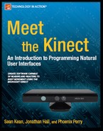
Originally, the only way to develop Kinect applications (apps) was to use a $10,000 Xbox Development Kit (XDK) supplied by Microsoft to its partners at high–level studios so they could design applications exclusively for the Xbox system (Figure 2-1, left). That changed dramatically only days after Kinect’s retail release – software drivers interpreted the signal coming from Kinect’s USB port, which was then written and released as open source software on the Internet. Suddenly, with the aid of the “libfreenect” drivers, also known as “OpenKinect,” anyone could develop their own apps using the Kinect sensor, free of charge. These drivers access raw data from various Kinect sensors, but don’t provide a higher-level framework for making sense of the data in a natural interface–based development environment. That didn’t stop curious and creative programmers from producing remarkable applications, also known as “hacks,” that explored the possibilities of Kinect technology beyond gaming (Figure 2-1, right).
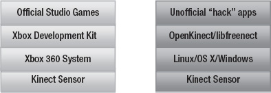
Figure 2-1. Original Microsoft Xbox Kinect stack vs. OpenKinect/libfreenect stack
Once unofficial Kinect apps began to gather media attention and online buzz, the companies that were previously designing software to enable the development of natural interface–based applications took notice. PrimeSense, the company that developed the enabling technology behind the structured light depth sensor inside Kinect, responded by spearheading the OpenNI initiative with a number of other industry leaders – a driver framework that allows interoperability between any depth–sensing hardware and the related software, which enables the creation of natural interface applications.
This gave developers another option for Kinect development – for the first time, they had access to a driver framework that would not require them to consider a particular manufacturer or the implementation of the depth–sensing hardware. Additionally, the OpenNI software came with tools that increased the speed of development because they solved many of the harder problems of working with raw sensor data that the libfreenect/OpenKinect drivers had not yet overcome. This software was freely available, and its source code was openly viewable. PrimeSense separately released a freely available, but closed source skeletal tracking middleware system called NITE that interprets raw data and computes simplified coordinates of body parts in order to author gesture input commands, which is similar to the technology used to create games with the Xbox Development Kit.
After OpenNI became available, Microsoft announced that a Kinect Software Development Kit for Windows would become available in the spring of 2011 for non–commercial use. Soon, companies that had spent years designing application development suites for authoring natural gesture software woke up to find a growing market demand. Previously, their systems were not easily available for download and came with licensing fees that made it too costly even to publish them on their websites. Suddenly, these companies needed to maintain relevance as thousands of developers were clamoring to create sophisticated applications – the most accessible choice was open source software. By February 2011, SoftKinectic announced the general availability of iisu, their driver system for any depth sensor as well as a development environment for body gestures, in addition to their line of DepthSense camera hardware. Omek Interactive moved to release their Beckon SDK while announcing a partnership with PMD Technologies, a time–of–flight depth camera manufacturer. GestureTek, a pioneer in body–based gesture interaction systems since the 1980s, prepared to offer their GestTrack3D SDK for general availability.
Gradually development choices have become increasingly diversified for designers and developers who are looking for tools that will help them take advantage of the possibilities offered by Kinect. Today, there are dozens of hardware and software combinations that result in novel technology stacks that can drive natural user interface experiences into the future (Figure 2-2). In the next section, we will explain the factors that determine the shape of a Kinect stack, based on the individual components.

Figure 2-2. New alternative natural interface hardware and software stacks
Hardware
A variety of devices can capture 3D imagery. Most are still expensive, which is why Kinect is such a significant breakthrough. Some devices are more appropriate for capturing still imagery, while other designs are suited for producing a high frequency of still imagery over time to generate 3D depth video. Each device captures depth information about the 3D world and stores it in ways that can reconstruct the full dimensionality of the captured 3D data. The systems may use very different operational approaches or come from different manufacturers, but the result is always data that contains some form of 3D depth information.
It can be helpful to compare the different approaches of collecting 3D imagery with the choices for collecting 2D information. Regardless of the device’s operational method, a traditional camera always captures the 3D world and stores it in a 2D format. Whether it’s a pinhole camera, a large format plate camera, a single lens reflex (SLR), a rangefinder, a point and shoot, or the camera in your phone, the optical systems take in light and store a negative or raw image file in flat 2D. Therefore, just as these different imaging systems exist with their own strengths and weaknesses for a particular application in 2D photography, there is a range of different ways to build 3D imaging systems as well. In depth–sensing systems, the basic premise usually includes emitting a signal, having that signal bounce off the objects in the environment, reading the signal as it returns, and computing the depth information (Figure 2-3). Regardless of the technique used, the common thread between them is the generation of a depth map image or a 3D point cloud of a scene.

Figure 2-3. Shared principles of most 3D depth–sensing systems. Signal is sent from the emitter, signal reflects back and is received by the sensor, calculations on returned signal are used to measure the distance to the target.
Structured Light Camera Systems
A visible structured light approach was famously used as the basis for Radiohead’s breakthrough 2008 cameraless music video, “House of Cards,” from the album In Rainbows. With the aid of Geometric Informatics’ custom system, close–up recordings of singer Tom Yorke’s face were captured as point cloud data, which allowed the ”synthetic camera” viewpoints to be directed in postproduction. The structured light approach was ideal for capturing the singer’s detailed facial expressions since this technique can be used to capture subjects within a couple of feet. Another 3D capture technique called LIDAR, or light detection and ranging, was used to gather large–scale 3D imagery spanning hundreds of feet for renderings of buildings and roads. A US$75,000 Velodyne device with 64 synchronized spinning lasers made this imagery possible.
The data resulting from the production of the Radiohead video was made openly available through a Google code repository at http://code.google.com/creative/radiohead/. Kyle MacDonald explains how to recreate a setup like the one used to create the close-ups in the video at http://www.instructables.com/id/Structured-Light-3D-Scanning/ (Figure 2-4).
Structured light scanning is the process of generating 3D depth imagery data by projecting a known signal on to a scene, such as bands of frequency, coded light, or a pattern of shapes, and observing the way this pattern is deformed as it strikes surfaces at variable distances to calculate depth range. Kinect uses an infrared structured light system, along with the ASUS WAVI Xtion and the PrimeSense reference designs. Because these systems use invisible infrared light, there is no perceivable disturbance to the environment during recording. This allows 3D capture to be unaffected by lighting conditions in the scene. In contrast, visible structured light systems work by projecting patterns on to a scene that is visible with the naked eye. Such systems provide their own illumination of the scene within the visible spectrum, which can be quite noticeable.
The visible structured light approach has some advantages. Previously, this approach was one of the less expensive options for generating depth imagery. It can produce higher resolution imagery than other approaches, such as time–of–flight cameras, at a fraction of the cost. In a visible structured light system, a projector can be used to overlay a pattern of shapes, such as lines, that are still or moving at high frequencies and bend around objects. One or more cameras are pointed at the structured light and calculations are processed on the resulting imagery to generate depth data. For example, the PR2 robot by Willow Garage uses an LED “texture” projector to overlay a pattern on the scene in front of the robot that looks like random red pixilated static. The Robot Operating System uses a narrow angle stereo camera pair that is pointed at the visible pattern to generate a 3D point cloud. Artists like Kyle MacDonald have successfully constructed visible structured light systems with off–the–shelf components (Figure 2-4) including the Sony Playstation Eye high–speed camera, DLP data projectors, and software written in Processing – an open source creative coding suite covered in Chapter 4. It is technically possible, although perhaps costly, to modify this visible structured light approach into an invisible structured light method if the projector signal and camera elements are adapted to work in the infrared range. This is the range of light the Kinect uses so the user doesn’t actively see light coming from the device.

Figure 2-4. Visible structured light setup pictured with a three–phase scanning technique. Lower frame shows resulting point cloud imagery that can be viewed from any angle. Image licensed by Kyle MacDonald under Creative Commons Attribution 3.0 Unported.
Kinect’s structured light approach is similar in principle to the technique used to scan visible light, as seen in Figure 2-4. A projector transmits a signal, a camera reads the signal, and computations are made to derive the distance of the objects from the camera for every pixel in the resulting depth image. However, the implementation details of Kinect’s approach, as designed by PrimeSense, are unique. Instead of projecting a visible stream of changing shapes or bands of light, the invisible infrared laser projector generates a static cloud of variably intense dots in a pattern that appears to be random. An infrared laser striking a diffraction grating creates each of the dots by splitting the beam into thousands of individual points of light.
How many dots of infrared light does Kinect project onto a scene? Some estimate 30,000 to 300,000 dots. One curious person went through the trouble of documenting the pattern and reconstructing it on a grid in order to understand how the dots were structured. His conclusion was that a 3×3 grid is a repetition of a 211 x 165 spot pattern, which creates an overall grid of 633 x 495 or 313,335 points of light in total (see http://azttm.wordpress.com/2011/04/03/kinect-pattern-uncovered/ for more information).
These dots look like random static, until you see that there is a repeating pattern with nine sections that make up a checkerboard. This light array is visible using a program like RGBDemo, which provides access to the IR image stream. The pattern is structured in a way that makes the detection of any set of dots registerable within the scope of the entire set – this is the essence of the architecture behind the PrimeSense depth sensor system (Figure 2-5). Because they are structured in such a recognizable way, the PrimeSense image processor chip can align these dots and make calculations based on them by comparing their different positions in order to create a reference image. When these cameras and chips are assembled into a system in the factory, all the components are calibrated by pointing the sensors at a wall, which are a specific distance from the device. The projector displays its structured pattern, and the IR camera captures an image that is stored on the PrimeSense chip as a registration of depth for all of the pixels in the image using that particular distance. For now on, this image becomes the reference point for calculating the distance to each pixel in a live depth image. The person’s face disrupts the uniform pattern and is compared to the reference image in a process that derives the distance to each dot on the face within centimeters.

Figure 2-5. PrimeSense depth sensor architecture. Color image CMOS sensor and audio components, colored blue, are not required to produce a depth map. Image courtesy of PrimeSense.
A special camera that can see infrared light is required to read all of the dots. This is the camera behind Kinect’s far right lens (Figure 1-6, D). This camera has a filter that masks the visible spectrum of light by only allowing infrared light to hit the light sensors behind it. If you look closely at this lens, you can see its iridescent green coating, which is how you can identify it from the visible light camera to its left. This barrier reflects all the unnecessary visible light that is not required for the depth calculating process, and only allows the infrared–projected dots to make it past the lens.
Kinect comes with another camera that is more familiar to us. It’s a simple webcam, similar to what your laptop or phone might contain that captures visible light as red–green–blue, or RGB pixels. The PrimeSense reference devices have this camera as well. However, another licensee, Asus, chose not to include the RGB camera in their first WAVI Xtion unit. This camera is not used to generate the depth map, yet is included in many new depth camera units as a method of mixing visible light imagery and depth imagery together. Systems that combine visible light with depth maps are a form of volumetric camera, especially when they are assembled in an array of multiple RGB/depth–sensing devices. Combining an array of sensors can produce imagery without shadows where no depth information is stored, which allows for an infinite perspective on a scene without noticeable gaps behind the objects.
Additionally, visible light cameras can be used for computational analysis. For example, computer vision recognition software, such as OpenCV, can be applied to a scene to search for faces, and be trained to associate those faces with individual users who are isolated from the depth map. There are a variety of existing libraries and methods for deriving meaningful information from RGB imagery that can be integrated into an application when the hardware uses this additional visible light camera.
The following subsections describe a number of depth sensors that implement the structured light approach for deriving 3D scene information. They all utilize the PrimeSense design, but have different choices for optional internal components and form factors. As PrimeSense continues to license the design to more manufacturers, such as those producing flat screen TVs and set top boxes, developers will find an ecosystem of choices that can be applied to design applications based on what they know about Kinect. Many of these hardware manufacturers will choose to participate in OpenNI–compliant or other standards–based app stores, which creates opportunities for app developers to distribute their creations to a larger base of installed devices.
PrimeSense Reference Design
PrimeSense is an Israel–based company that makes the 3D–structured light technology that Microsoft licensed for use in Kinect. A reference design product is available for developers to evaluate the technology for use in new hardware, or for working with the OpenNI/NITE software that will be covered in subsequent chapters. For the scope of this book, PrimeSense’s reference design is the same as Kinect’s. The only differences are the lack of a motor, the need for an A/C power supply, and different microphone components. The PS1080 design (Figure 2-6) was the first available and is being replaced by a smaller model with a built-in stand. (More information is available at http://www.primesense.com).
![]() Tip The Xtion Pro Live manufactured by ASUS and mentioned in the next section is an exact implementation of the PrimeSense reference design. If you want an implementation of the reference design and have trouble getting the one from PrimeSense, the Xtion Pro Live is a good option.
Tip The Xtion Pro Live manufactured by ASUS and mentioned in the next section is an exact implementation of the PrimeSense reference design. If you want an implementation of the reference design and have trouble getting the one from PrimeSense, the Xtion Pro Live is a good option.

Figure 2-6. The original PrimeSense reference design, the PS1080 (top), and the newer design (bottom)
PrimeSense is the primary designer of infrared structured light systems. However, other hardware manufacturers produce depth imagery using alternative techniques that are described in upcoming section “Time–of–Flight Camera Systems”. It is important to remember that regardless of the design, all of these sensors generate a depth map that can be incorporated into software using similar principles. As we get to the driver section of the stack, you’ll see that there are layers of software that abstract out the particular hardware implementation and simply give you access to the 3D data regardless of the method used to generate it.
ASUS WAVI Xtion PRO and PRO Live
ASUS, a Taiwanese computer manufacturer, was the second major licensee of the PrimeSense hardware technology after Microsoft. The WAVI Xtion PRO is marketed as “the world’s first and only professional PC motion–sensing software development kit.” The distinction is warranted because, unlike Kinect, this product was designed with the intention of connecting it to a personal computer right out of the box and is developer–friendly with software and content creation tools intentionally included. Developers who build OpenNI–compliant software will have an opportunity to sell it in the ASUS Xtion store that will accompany the WAVI Xtion product line.
More recently, ASUS has introduced the Xtion PRO Live. This newer model includes an RGB camera, and is a precise implementation of PrimeSense’s reference design. More information about both models is available at http://event.asus.com/wavi/Product/WAVI_Pro.aspx.
![]() Note Following is the direct link to the ASUS store page from which you can purchase the PRO Live model:
Note Following is the direct link to the ASUS store page from which you can purchase the PRO Live model: http://us.estore.asus.com/index.php?l=product_detail&p=4001.
Time–of–Flight Camera Systems
In contrast to structured light systems, time–of–flight camera systems don’t make use of a complex projected pattern that needs to be decoded in order to calculate depth. Instead, these systems make use of the constant speed of light, approximately 300 million meters per second, as the key to unlocking the depth of objects in a scene. This depth ranging technique works by recording the time it takes a light signal to travel from an emitter and bounce off an object in a scene, and eventually land back on a light sensor in the unit. Extremely sensitive photo sensors and high–speed electronic components allow for a calculation of distance to be made based upon the time it takes for the light to travel and bounce back. This calculation is performed for every element in the sensor array, which requires the resolution of these devices to be smaller than that of structured light systems, usually between 64x48 and 320x240 pixels.
There are a number of techniques—such as pulsed light, RF modulation, and range gating—that manufacturers can use to make a time–of–flight system. Additionally, one can choose what type of light source to use, which determines the price and suitability of a given environment. An array of LEDs can be used to construct a consumer–priced system that works well for close range subjects, between two centimeters and two meters. Laser light–based systems have the ability to extend up to two kilometers, but these are out of the price range for anyone but large institutions.
LED–based time–of–flight sensors make up the bulk of the competition against PrimeSense structured light depth sensors. The following section highlights the devices that are marketed for use in 3D natural interface systems. Because of the way these systems are designed, they have abilities that structured light systems are unable to match. Depending on the type of illumination employed and the availability of ambient light suppression, time–of–flight units can be used outdoors in daylight. Structured light systems are often unable to compete with the strength of light beyond indoor conditions. Additionally, time–of–flight chip timing can be altered to provide depth precision over a large distance, or it can be densely tuned to a small depth range, making these systems suitable for facial capture where a high degree of detail is required over a short distance.
SoftKinetic DepthSense Cameras
SoftKinetic is a Belgium–based company that is bringing its DepthSense line of cameras to the US market along with their 3D gesture recognition middleware, iisu. Their DepthSense cameras gather 3D scene information using time–of–flight systems and include an RGB camera for sensing visible light imagery similar to Kinect. Their DepthSense hardware enables the natural motion based interface for the first game console designed for the Chinese market, iSec (http://www.eedoo.cn/html/eedoo/isec/). More information about SoftKinetic is available at http://www.softkinetic.com/.
PMD [vision] time–of–flight cameras
PMDTec, headquartered in Germany, is the world’s leading supplier of integrated circuit technology for time–of–flight cameras. Their PMD[vision] CamBoarreference design has a grid of 200x200 sensor elements and provides companiesd reference design has a grid of 200x200 sensor elements and provides companies that want to build their own products around this technology with an idea of how it can be implemented, similar to the relationship between PrimeSense and Microsoft with Kinect. The PMD [vision] O3 on the other hand, is packaged to be purchased direct from PMD and contains a sensor grid of 64x48 elements. These two devices (shown in Figure 2-7) do not come with an integrated RGB camera so they can only provide a depth and IR map. PMDTec’s newest high–resolution prototypes capture up to 352x288 sensor elements. (More information is available at http://www.pmdtec.com/).

Figure 2-7. The PMD [vision] CamCube, PMD [vision] CamBoard reference design, and PMD [vision] ConceptCam. Photo by Kara Dahlberg.
Panasonic D-Imager
Panasonic’s D-Imager shown in Figure 2-8 is marketed as a depth–sensing solution for gaming systems and digital signage. It was used to drive an interactive display at the Japanese pavilion during the World’s Fair EXPO 2010 in Shanghai. The D-Imager can produce a 160x120-resolution depth map image at up to 30 frames per second. Panasonic’s device contains back light suppression technology to make it more resilient to bright ambient light conditions. More information is available at http://panasonic-electric-works.net/D-IMager.

Figure 2-8. Panasonic D-Imager time–of–flight depth sensor with an array of near infrared LEDs hidden to the left and right of the lens.
Drivers & Data
Each of the devices mentioned in the previous hardware sections require drivers that can interpret the raw signals coming out of them and turn those signals into usable data for applications. Drivers are the next layer in the technology stack and are critical for developing software that can take full advantage of these devices on a given platform.
The original manufacturers only provide drivers for these devices on platforms that they support. This was the case with Kinect when it was initially released. Kinect was only usable on Xbox 360 systems until the open source community reverse–engineered the device to produce the OpenKinect project and the libfreenect drivers. Since then, there are multiple ways to work with Kinect on the platform you desire, or with any of the other depth–sensing cameras listed in the previous hardware section. This is all thanks to the magic of drivers – let’s look at the kind of data supplied by different drivers.
OpenKinect/Libfreenect
The OpenKinect project’s “libfreenect” open source driver for Kinect was the first available for general use and is the basis for a number of projects. Once the OpenNI driver framework came out, many projects dropped their dependencies on ‘libfreenect’ and moved over to the OpenNI drivers because they offered more flexibility for swapping out Kinect for other hardware, as well as a more robust set of features to build applications on top of. That said, many programmers still choose to use the “libfreenect” driver because it is easy to redistribute without requiring users to download dependent software.
Libfreenect provides access to three main sets of data from Kinect in the form of imagery. The most important data is the raw depth map image (Figure 2-9). This is libfreenect’s only way of providing depth information for your application. This image is encoded to an 11-bit depth and the intensity values map to a specific distance from the camera. The rawest form of data displays this in shades of gray, yet most utilities choose to display it as a colored image in order to distinguish between distances visually.
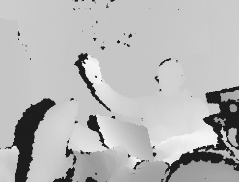
Figure 2-9. Depth map image from Libfreenect. Each color represents a distance from the camera.
The libfreenect driver also provides your application with a raw infrared (IR) image using the far right camera (Figure 2-10). The driver uses a direct feed from the camera that is designed to look for the dots of light produced by the IR projector. For that reason, image is filled with a speckled pattern that is dispersed around the objects in the scene. Because the IR map is used to generate the depth map, combining the two in a point cloud view provides a well–aligned 3D representation. However, the representation must be calibrated. This need for calibration is one of the frustrating aspects of using the Libfreenect drivers – OpenNI provides a calibrated mapping of the RGB data for the depth data.

Figure 2-10. IR map image from Libfreenect. Speckled dots are projected on the scene from the IR projector.
The final image data provided by Libfreenect is the visible light RGB image (Figure 2-11) from the middle camera in Kinect. The RGB camera provides the visual data you would work with to perform calculations on a scene using computer vision software, such as OpenCV, for face recognition. As you’ll see in Chapter 3’s coverage of the Body Dysmorphia Toy and the Ultra Seven/Kamehameha apps, this visual data can also be fed back into the software you produce to provide an augmented reality view. Your application can also align the RGB image data with the depth map to produce point clouds that will reconstruct a scene like 3D Capture-It, which is also covered in Chapter 3.

Figure 2-11. RGB map image from libfreenect
In addition to the image–based sensor data, Libfreenect also provides access to the 3-axis accelerometer chip embedded in Kinect. This could be helpful for designing hand-held applications that require users to move Kinect manually, as MatterPort does in Chapter 3. Libfreenect lets your application read data, but it also control actuators on Kinect. The LED light can turn different colors and turn on and off according to your design. The Kinect head can be tilted 30 degrees up or down using the motor–control function.
OpenNI
As described on www.OpenNI.org, “the OpenNI organization is an industry–led, not–for–profit organization formed to certify and promote the compatibility and interoperability of Natural Interaction (NI) devices, applications, and middleware.” To carry out this mission, and with the strong support of PrimeSense, the organization has created an open source framework called OpenNI that provides an application–programming interface (API) for writing applications that use natural interaction. The API covers communication with low–level devices, such as vision and audio sensors, as well as high–level middleware solutions for visual tracking using computer vision.
OpenNI provides access to all of the data available through the Libfreenect driver. It also provides benefits such as methods for converting from projective x, y coordinates of the depth map back to real world x, y, and z coordinates in centimeters. This makes it easier to acquire a point cloud and generate alternate viewpoints in a scene from synthesized camera views (see Figure 2-12). Additionally this software provides the ability to track multiple people, and extract their gestures from skeletal body data.
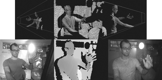
Figure 2-12. Upper row, point cloud rotated to show alternate viewpoints. Lower row, source RGB, depth, and IR map images for point cloud scene.
Commercial Drivers
The various software development kits designed to build applications for natural interaction all come with their own series of drivers for Kinect and have other depth sensors built in. SoftKinetic’s issu, Omek Interactive’s Beckon, and Gesturetek’s GestTrack3D have their own implementations and may have varying ways of working with the device. In terms of the microphone array inside Kinect, Microsoft’s drivers for Windows contain features not available in other drivers. Microsoft’s Kinect SDK is not yet licensable for commercial use, but we expect that situation to change early in 2012 when Microsoft releases a commercial version of their SDK.
Middleware and Application Development Environments
The last major component of the stack is the so–called Middleware – various modules of software that act on sensor data and produce new functionality that an application can use. This type of functionality may be incorporated into integrated application development environments so the degree to which you are made aware of them as separate middleware modules depends on the software environment you are using to design your application.
The ability to segment the depth map into isolated users (Figure 2-13, left) that are separated from the background, or to extract and track a user’s hand (Figure 2-13, right) are functional time–saving modules that can help you develop applications more quickly, and that dramatically reduce your codebase’s size.

Figure 2-13. Left, user segmentation tracking two people. Right, demonstration of a point tracking a hand
The details of how to interface with this functionality may be different depending on the development environment you chose to work in. However, the underlying concepts are similar. Skeletal tracking middleware can track a user by segmenting that user into a skeleton with a series of “body data” joints. These joints can be assigned matching values in your application for puppeting a character or to listen for recognizable gestures.
As we move on to Chapter 3 and review applications in the wild, make note of how the programmers have used the methods we’ve identified in this chapter. Now that you’re aware of how the technology works, you’ll have a better idea of how to start making your own motion– and depth–aware apps.