Water and Membrane Treatment
Abstract
Water treatment in membrane plants implies pre-treatment and often post-treatment also. Pre-treatment is mandatory because membrane systems are susceptible to fouling. The extent of physical and chemical pre-treatment depends on the quality of raw water, e.g. well water typically require minimum pre-treatment, whereas wastewaters require extensive pre-treatment. Both physical and chemical pre-treatment processes and technologies are discussed in detail. Post-treatment technologies are also detailed. Post-treatment is required depending on the application of product water at the point-of-use, e.g. RO permeate is remineralised prior to distribution for potable use. Conversely, RO product water is polished to further demineralise it for applications that require high-purity water (pharmaceuticals) or ultrapure water (microelectronics). Membrane scaling/fouling, process design guidelines to minimise fouling and membrane cleaning are discussed in detail. This chapter describes in detail membrane system designs including important design features and system controls.
“Whisky is for drinking, water is for fighting over.”
— Mark Twain
2.1 Priceless Water
Current shortages of potable water around the world and the looming water scarcity, especially in the developing countries, is the greatest crisis facing humanity in the twenty-first century and possibly beyond [1–3]. According to the UN, 1.2 billion people do not have access to clean drinking water, and half of the world’s population lacks adequate water purification. By 2025, 1.8 billion people will be living in areas likely to experience absolute water scarcity [1]. One-third of the world’s population that currently lives in water-stressed countries is expected to rise to two-thirds by 2025. By the year 2050, between 2 and 7 billion people will face water shortages. Inadequate supply of potable water, coupled with higher water demand in developing countries due to rapid population growth and industrialisation, are among the major reasons for the worsening water situation.
Nearly 60% of illness around the world is due to contaminated water and lack of sewer treatment. According to the World Health Organisation (WHO), about 2.4 billion people do not have access to basic sanitation facilities, and more than one billion people do not have access to safe drinking water. Unclean water causes diarrhoea, cholera, dysentery, guinea worm infection, typhoid, intestinal worm infection and trachoma [3]. According to the WHO, four billion people get diarrhoea every year that kills nearly 1.8 million people of which 90% are children under the age of five.
Although water is the most common substance in the world, only 3% is fresh water (97% is seawater), and only 1% is available for human consumption. According to many experts even 1% is adequate since fresh water supply is infinite because of the natural water cycle [1,3]. However, the availability and application of water is uneven around the world; in water-stressed countries such as India, China as well as in countries in South-East Asia, Northern Africa and North-East Africa, the situation is especially acute. In India, for example, groundwater from aquifers is being pumped at nearly twice the rate of aquifer recharge from rainfall, while both the demand for water and the country’s population is expected to increase at least 50% by 2050 [4].
Further, the quality of available or useable water is decreasing due to increasing water pollution from industrial, agricultural and other human activity. In fact, it is becoming a major environmental problem today. For example, due to excessive use of fertilisers in India’s bread-basket state of Punjab during the last 40 years, the nitrate level in groundwater has exceeded the carcinogenic level of 50 parts per million (ppm) in many areas [4]. Nitrates are a health concern because they are converted to nitrites which interfere with hemoglobins to exchange oxygen in blood. This can cause serious problems especially for fetus and children. Nitrate residues also accelerate eutrophication – enrichment of ponds and lakes by nutrients that results in oxygen depletion – of water bodies. Another major source of water pollution is chlorine, which is used in pulp and paper bleaching, metal processing, pharmaceutical manufacturing, textile dyeing and cleaning, corrosion control, photography and water treatment [3]. Arsenic, a carcinogen at concentrations greater than 10 parts per billion (ppb), occurs naturally in groundwater in several countries. The problem is especially acute in Bangladesh where 60 million people are seriously affected by arsenic in natural drinking water. Similarly, endocrine-disrupting compounds in wastewaters from pharmaceutical, cosmetic and food processing plants in even trace amounts (ng/l) are carcinogenic, and pose a problem due to incomplete removal by conventional primary and secondary treatment processes. Prominent among the endocrine disrupting contaminants are steroid hormones that are continuously excreted by humans and animals.
Scarcity of water resources is also often the limiting factor for economic and social development. Water is needed not just for drinking, household purposes and for agriculture, but also for manufacturing goods, food processing and power generation. Industrial water purification has been growing in the US at approximately twice the GNP, according to the American Society of Testing Materials. Highly purified water plays a critical role in the manufacture and use of advanced materials such as biotechnology, quenching of turbine forgings, final rinsing of fluorinated polymer films, manufacture of new glass laminates, and the use of ultrahigh purity (resistivity ≥ 18.2 MΩ-cm) water in the production of graphite fibres and microchips. Current and looming water scarcity and the effects of environmental pollution, groundwater degradation and global warming on water availability can have severe and adverse effects on the world economy, especially developing countries. This may lead to human displacement at an unprecedented scale. It is imperative, therefore, that existing water resources are preserved and advanced treatment processes are deployed to provide potable water.
Water demands and its quality depend on its usage, which varies from region to region. Water shortages have been attributed to varied reasons such as nearly 50% loss due to leaks in piped water systems and inefficient usage of water (70–90% of available water) for agricultural irrigation. For example, intensive and indiscriminate pumping of groundwater is depleting the huge Ogallala aquifer in middle America eight times faster than it is being replenished. Similarly, excessive use of water required for high-yielding grain crops is depleting groundwater in the Punjab region of India [4]. Water scarcity problems, however, can be solved by a combination of water conservation, reclamation, recycling and desalination, as discussed in Chapter 3.
Industrial water management relies heavily on separation science, e.g. coagulation and flocculation are used to separate or remove suspended solids from water for clarification by accelerating their settlement rates during conventional treatment. Membrane filtration processes – ultrafiltration (UF) and microfiltration (MF) – are being used for treating waste water in lieu of coagulants such as aluminium sulphate (alum) and polymers, thereby eliminating the production of sludge and its disposal (see Figure 3.47). Separation techniques such as adsorption, ion-exchange, membrane separation and chemical coagulation and precipitation are being deployed for removing arsenic from groundwater.
RO membrane separation has been traditionally used for seawater and brackish water desalination, and production of high-purity water for food, pharmaceutical processing and industrial waste treatment, as discussed in Chapter 1. The development of nanofiltration (NF) membranes has opened up many areas of application including water softening, removal of disinfection by-product precursors (trihalomethanes), removal of total organic carbon (TOC), food processing and industrial water treatment [5].
Low-pressure membrane filtration using MF and UF membranes is becoming the separation processes of choice for municipalities for removing turbidity and pathogens [6,7]; membrane filtration has proven to be very effective and reliable in removing microbiological parasites, Giardia and Cryptosporidium, since first used in this application in 1995. Increasingly integrated UF/MF-RO membrane systems are being used for the reclamation of industrial and municipal water where UF or MF replaces conventional filtration for treating RO feed water, e.g. treating secondary treatment effluent with membrane filtration followed by RO membrane treatment for producing water for industrial use and aquifer recharge, and RO seawater desalination pre-treatment [8]. Several case studies of integrated membrane systems used in water treatment are discussed in Chapter 3.
The reasons why membrane filtration is becoming the preferred technology for water treatment complementing RO or NF membrane systems are detailed below:
• Development of high-frequency backwashed UF and MF processes for combating membrane fouling using high integrity hollow fibre membranes.
• Application of dead-end MF/UF systems, well-suited for municipal raw water treatment because of low particle count.
• Reliable and consistent high-quality product water including removal of parasites and pathogens.
• Minimal use of chemicals thereby meeting stringent water pollution standards with ease.
• Reliable and well-established membrane plant operation.
• Automated control of systems resulting in reduced operating labour costs.
• Small footprint and modular design allowing for easy future expansion.
• Increasingly cost-competitive; the cost of RO membranes dropped substantially in the last two decades while the permeate production has increased threefolds [9].
• Proven integrity of membranes albeit with a limited life span of 3–5 years for polymeric membranes. Ceramic membranes, which last longer, are also being deployed but are expensive.
2.2 Water Treatment
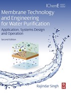
The types of impurities depend on the water source. The feed water could be ground water, well water, surface water, seawater, brackish water, or municipal wastewater. Water composition of some typical waters is given in Table 2.1. Surface water usually contains suspended solids, colloids and organics including high bacteria count, and has significant variable quality during the year. Ground water and well water usually have low amounts of suspended matter but may contain iron, manganese and hardness ions of calcium and magnesium [10]. Industrial wastewaters are regulated for suspended solids, free oil and grease, pH and biochemical oxygen demand (BOD) and heavy metals, and often contains mineral acidity, detergent compounds and trace amount of chemicals and heavy metals due to industrial pollutants. Membrane separation processes are also used to treat these waters for environmental pollution control [11].
Table 2.1
Composition of typical feed waters
| Item/ion | Rivera | Lakeb | Wellc | Brackishd | Seawater |
| Cations | |||||
| Calcium | 50e (125f) | 38 | 114 | 129 | 400 |
| Magnesium | 14 (57.4) | 8 | 19 | 89 | 1252 |
| Sodium | 35 ( 76.3) | 11 | – | 521 | 10,561 |
| Anions | |||||
| Bicarbonate | 158 (129.5) | 117 | 170 | 161 | 140 |
| Carbonate | 1.2 (2) | – | – | – | – |
| Hydroxyl | – | – | – | – | – |
| Sulphate | 97 (100.9) | 26 | 29 | 1260 | 2650 |
| Chloride | 16 (22.6) | 18 | 76 | 262 | 18,980 |
| Nitrate | 4.6 (3.7) | 1.8 | – | – | 1.5 |
| Fluoride | – | – | 0.1 | – | 1.4 |
| Boron | – | – | – | 2.8 | 4 |
| Other | |||||
| Silica | 13 (2.1) | 12 | 10 | 49 | – |
| Iron | 0.1 (0.01) | 3.5 | Trace | 1.2 | – |
| Manganese | – | 0 | 0.01 | – | – |
| pH | 7.9 | 6.8 | 7.5–8.4 | 7.7 | – |
| Turbidity | 58 | 0–20 | 0 | – | – |
| TDS | – | – | – | 2478 | 33,990 |
| Alkalinityf | 132 | 96 | 140 | 133 | 115 |
| Hardnessf | 183 | 128 | 363 | 692 | 6133 |
a Mississippi.
b Lake Erie.
c West Virginia.
d Coalinga, California.
e Ion as mg/l.
f Ion as CaCO3.
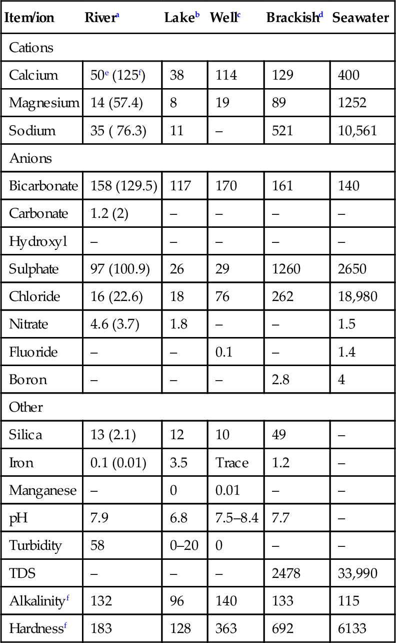
Once the feed water source has been determined, analysis of the feed water composition is necessary before a treatment system can be designed. Feed water constituents that must be analysed prior to designing a RO/NF membrane system as per ASTM Designation D4195-88 “Standard Guide for Water Analysis for Reverse-Osmosis Applications” are discussed in Chapter 6. Typical water treatment methods are summarised in Table 2.2.
Table 2.2
Water constituents and treatment methods
| Constituent | Chemical formula | Effect/problem | Treatment |
| Turbidity | None (expressed as Jackson Turbidity Units, JTU) | Imparts unsightly appearance to water. Deposits in water lines and process equipment. Interferes with most process uses | Coagulation, settling and filtration |
| Colour | N/A | May cause foaming in boilers | Coagulation, and filtration, chlorination, activated carbon, anion exchange, NF |
| Hardness | Ca2 + and Mg2 + salts expressed as CaCO3 | Chief source of scale in heat-exchange equipment, boilers and pipelines. Forms curds with soap, interferes with dyeing | Softening, demineralisation, surface-active agents, NF, RO, ED |
| Alkalinity | HCO3− CO3− 2 and OH− expressed as CaCO3 | Foaming and carryover of solids with steam. Embrittlement of boiler steel. Bicarbonate and carbonate produce CO2 in steam, a source of corrosion in condensate lines | Lime and lime-soda softening, acid treatment, hydrogen zeolite softening, demineralisation, dealkalisation by anion exchange, degasification |
| Free mineral acids | H2SO4, HCl, etc. expressed as CaCO3 | Causes corrosion | Neutralisation with alkalies |
| Carbon dioxide | CO2 | Causes corrosion in water lines, particularly steam and condensate lines | Aeration, deaeration, membrane contactors, neutralisation with alkalies |
| pH | Hydrogen ion concentration defined as: pH = log(1/H+) | pH varies according to acidic or alkaline solids in water. Most natural waters have a pH 6.0–8.0 | pH can be increased by alkalies and decreased by acids |
| Conductivity | None (expressed as microSiemens/cm) | High conductivity can increase the corrosive characteristics of water | Demineralisation, lime softening, RO, ED, NF |
| Nitrate | NO3− | Adds to solids content. Useful for control of boiler-metal embrittlement | Demineralisation, distillation, RO, ED |
| Silica | SiO2 | Causes scale in boilers and cooling water systems, which forms insoluble turbine blade deposits | Hot-process removal with magnesium salts, adsorption by highly basic anion-exchange resins, in conjunction with demineralisation |
| Sodium | Na+ | Adds to solids content of water. When combined with OH−, causes corrosion under certain conditions | Demineralisation, RO, ED, distillation |
| Aluminium | Al+ 3 | Usually present as a result of floc carryover from clarifier; can cause operation deposits and contribute to scaling | Improved clarification and filtration |
| Iron | Fe+ 2 (ferrous) Fe+ 3 (ferric) | Discolours water on precipitation. Source of deposits in water lines, and boilers. Interferes with dyeing, tanning and papermaking | Aeration; coagulation and filtration, lime softening; cation exchange; contact filtration, surface-active agents for iron retention, greensand filtration |
| Manganese | Mn+ 2 | Same as iron | Same as iron |
| Oxygen | O2 | Causes corrosion of water lines, heat exchange equipment, boilers and return lines | Deaeration, membrane contactors, sodium sulphite, corrosion inhibitors |
| Hydrogen sulphide | H2S | Causes of “rotten egg” odour and corrosion | Aeration, chlorination, strong basic anion exchange |
| Ammonia | NH3 | Corrosion of copper and zinc alloys by formation of complex soluble ions | Cation exchange with hydrogen zeolites, chlorination, deaeration |
Source: Branan, Gulf Publishing Co., 1998.
In the case of municipal wastewater for reclamation, secondary treatment effluent is often the feed water for membrane plants. Preliminary and primary treatment remove heavy solids, fine suspensions, grease and fats. Sometimes raw water is chlorinated for odour control. In the case of raw municipal wastewater, primary treatment removes 30–50% of suspended solids. The remaining organic matter is removed in biological secondary treatment [12,13]. Typically, RO/NF feed water is primary treatment effluent except when the feed water source is brackish water or seawater. RO/NF pretreatment is used to remove (a) certain dissolved solids and minerals, (b) organics, (c) virus and pathogens, (d) trace metals, (e) nutrients, and (f) removing remaining suspended solids in order to minimise fouling and scaling. The water treatment unit operations (UOPs) discussed include [10,12,14]:
• Softening
• Granular media filtration
• Activated carbon filtration
• Membrane filtration
• Deaeration-Decarbonation
• Chemical oxidation
• Disinfection
• Electrocoagulation
• Ion exchange (IX)
When RO product water needs to be polished to produce higher grade water, several or all of UOPs listed below are also required. These UOPs remove trace amounts of contaminants such as ions, gases, particles, microorganisms and organic compounds:
• Electrodeionisation (EDI)
• Membrane degasification
• TOC ultraviolet radiation
Besides feed water characteristics and product water quality, capital costs (CAPEX) and operating costs (OPEX), manpower, space availability, and future expansion requirements, and the efficacy of the specific techniques are considered in developing a water treatment system for a given application.
2.2.1 Coagulation
Coagulation is a chemical process for removing particles in suspended or colloidal form. These particles do not settle on standing and cannot be removed by conventional physical treatment processes. The settling time for silt, for example is about 3 h as compared to 3 years for colloids. Suspended solids and colloids resist agglomeration because of the similar electrical charge (usually negative charge) on their surfaces that creates a mutually repellant force. The charge repellant behaviour is depicted in Figure 2.1 and is explained by the concept of “Zeta Potential” in Chapter 6.

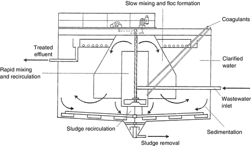
Colloids are particles in the size range of 0.1 (10− 8 cm) to 1 nm (10− 7 cm). They are either hydrophobic (e.g. clays) or hydrophilic (e.g. poorly ionised organic acids). High-valence cation (Mg2 +, Al3 +) coagulants neutralise the negative charges thereby allowing the particles to come together or coalesce; the larger particles then precipitate and removed via sedimentation or filtration. A clarifier used for both coagulation and settling is shown in Figure 2.2. Chemical coagulants include aluminium sulphate (alum), ferric chloride, lime and polymers (see Table 6.8). Low-molecular-weight cationic polymers and inorganic aluminium and iron salt (e.g., alum and ferric sulphate) are the most commonly used positively charged coagulants [10,12,14].
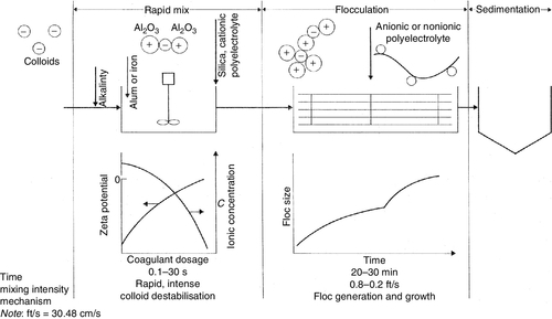
Coagulation is a two-step process: first, the zeta potential is reduced to a level below the van der Waal’s attractive forces, and second, the micelles aggregate to form clumps that agglomerate the colloidal particles [10,12,13]. The mechanism of the coagulation process is shown in Figure 2.3. For an effective coagulation, alkalinity should be added first (bicarbonate provides alkalinity without raising the pH), alum or ferric salts are added next, and coagulant aids such as activated silica and/or polyelectrolyte for floc build-up and zeta potential control are added last. Activated silica is a short chain polymer that binds together particles of microfine aluminium hydrate. Polyelectrolytes are high-molecular weight polymers capable of forming bridges between particles or charge flocs. Large flocs (0.3–1 mm) are created when small dosages are added with alum or ferric chloride.
The reaction of alum [Al2(SO4)3 · 18H2O] when added to water in the presence of alkalinity is:
The alum floc is least soluble at a pH of about 7.0; the floc charge is positive below pH 7.6 and negative above pH 8.2. Aluminium hydroxide is amphoteric and acts as either an acid or a base.
There are three types of polyelectrolytes: cationic, anionic and non-ionic. Sometimes cationic polymers are added as a coagulant. The polymers bring the system to the isoelectric point without a change in pH. Although polymers are many times more effective than alum, they are quite expensive. The dosage range for a cationic polymer is 2–5 mg/l vs. 75–250 mg/l for alum. The dosage range for anionic and non-ionic polymers is 0.25–1.0 mg/l.
Some clarification systems concentrate on producing only a fine or pin floc, which is then removed by in-line coagulation (coagulants are typically fed to the influent side of a media filter and allowed to mix in-line with the aid of an in-line mixer). In-line coagulation increases particle size and, therefore, filterability of solids that have carried over. Typical coagulant feed rates range from 0.5 to 20 mg/l, with dosage for inorganic coagulants generally higher than polymeric coagulants. This process eliminates the large settling clarifier and produces high clarity water more quickly in smaller equipment.
2.2.2 Softening
Softening refers to removing calcium and magnesium hardness by chemicals. However, silica, alkalinity and other constituents are also removed during lime softening. Other water softening methods include ion exchange and NF membrane separation.
Lime softening
Lime, sodium carbonate (soda ash), and/or sodium hydroxide (caustic soda) are added to water to convert soluble calcium and magnesium hardness to insoluble calcium carbonate and magnesium hydroxide in a contact vessel for 60–90 min [10,12,14]. Lime is not a true coagulant but reacts with bicarbonate alkalinity to precipitate calcium carbonate. Magnesium hydroxide precipitates at high pH levels. The solids are collected as sludge from the bottom of the settling basin. The sludge-free water is clarified by filtration to remove any turbidity and remaining solids thereby ensuring there is no carryover.
Calcium and magnesium occur as bicarbonates primarily. Lime and caustic soda break down the bicarbonate ions (HCO3)− into water molecules and insoluble carbonate ions (CO3)2− as follows:
Similarly, lime or caustic soda are used to provide hydroxide for precipitation of magnesium hardness as Mg(OH)2. Hardness may also be present in non-carbonate form as sulphate, chloride, or nitrate. In the case of non-carbonate calcium compounds, carbonate for precipitation is provided by adding sodium carbonate (soda ash):
Cold lime softening is never complete because calcium carbonate and magnesium hydroxide are slightly soluble in water. Hot lime softening (HLS) with water heated to 100°C, on the other hand, significantly reduces silica in addition to hardness and alkalinity. Heating aids in the completion of the softening reaction, which in turn increases the efficacy of silica removal by providing more solids, particularly magnesium hydroxide that absorbs silica. HLS is not, however, used for potable water applications. Lime softening is followed by filtration to remove any turbidity and solids. Inorganic coagulants are typically used to minimise carryover in cold process softening, whereas anionic polymers are used with hot process softening. Effluent hardness from a cold process softener ranges from 35 to 80 mg/l; effluent hardness from a hot process softener is as low as 10–40 mg/l. In order to reduce the hardness further (1 mg/l), ion-exchange softening is required.
Coagulants are often added in conjunction with lime to increase the settling rate of calcium carbonate and magnesium hydroxide. Most of these coagulants are acidic in nature and react with the alkalinity of the water. Commonly used coagulants include aluminium sulphate (alum), sodium aluminate, ferric sulphate and ferrous sulphate (Table 6.8). Alum reacts with natural alkalinity in water to form aluminium hydroxide floc (Equations 2.5–2.8) [14]. About 1 ppm of alum decreases water alkalinity by 0.5 ppm and produces 0.44 ppm of CO2:
Ion-exchange softening
Water softening by ion exchange (IX) uses strong acid cation (SAC) resins in the sodium form (− SO3Na) to remove scale-forming cations from water [10,12,14,15]. Ion-exchange softening involves the exchange of hardness ions such as calcium, magnesium, strontium and barium for sodium ions to yield low hardness, or “soft” water (the softened water has a higher total dissolved solids (TDS)), as shown in Equation (2.9), where a cation resin (R) selectively removes calcium ions by the following reaction:
IX softening is typically used when the hardness is in the range of 50–500 mg/l [16], and for feed water flow rates of up to 60 m3/h (see also Chapter 6).
The exhausted resin is regenerated with a dilute NaCl (brine) solution. This removes calcium and magnesium in the form of their soluble chlorides and at the same time restores the resin to its original sodium form. The bed is rinsed free of undesirable salts and returned to service. The regeneration reaction may be written as:
The IX softeners normally operate at linear velocities of 14–20 m/h. About 8.5 lb (3.9 kg) of salt (NaCl) is required to regenerate 1 ft3 (0.3 m3) of resin, and remove approximately 4 lb (1.8 kg) of hardness. Hardness is given in grains/gallon or in ppm as CaCO3. The reduction is directly related to the amount of cations present in raw water and the amount of salt used to regenerate the resin bed. Typically, 6 lb of NaCl/ft3 of resin is used for regenerating SAC resins.
Ion-exchange dealkalisation usually employs weak acid cation (WAC) carboxylic acid resins operating on the hydrogen cycle. Dealkalisation and alkaline hardness removal are synonymous terms that mean the water is only partially softened after such a treatment. Complete softening may be achieved by treating it further in the conventional sodium cycle to remove the remaining permanent hardness. The high selectivity for divalent ions such as calcium and magnesium over monovalent sodium ions results in the preferential exchange of calcium and magnesium ions (denoted M2 +) [15]:
In the presence of hydrogen ions, the above exchange does not occur. However, if alkaline hardness (bicarbonate) is present, the exchanged hydrogen ions are immediately neutralised by the basic bicarbonate and carbonate anions to give carbon dioxide, which dissolves in water as weak carbonic acid:
The exchange of calcium and magnesium ions continues until all basic anions are neutralised after which time no further exchange can occur. Hence, the extent of hardness removed is equivalent to the alkaline hardness of the water. The resins are regenerated with either dilute hydrochloric acid or dilute sulphuric acid over a period of 30 min. The weak acid resin is regenerated at virtually 100% efficiency. Weak base anion (WBA) resins are also effective in removing strong mineral acid anions such as sulphates, chlorides, and nitrates. Hence, as in the case of IX softeners, WBA are sometimes used to treat RO feed water, thereby, reducing the potential of mineral scaling of RO membrane surface. The exhausted bed is regenerated with sodium hydroxide (caustic soda).
NF softening
Membrane softening by NF is a relatively new application as discussed in Chapter 1. NF membranes (“loose RO”) operate at a lower feed pressure than RO membranes, and have a high rejection (99%) of divalent hardness ions. It is a more attractive alternate to lime softening and IX softening because not only is it a reliable process, no regeneration is required and, thus, there is no chemical wastewater. NF separation like RO is a continuous process and is independent of the plant capacity (flow rate) and feed water hardness. It reduces both the hardness and the TDS to a much greater degree than IX and lime softening [5].
2.2.3 Granular media filtration
Granular media filtration (GMF) is a process for removing suspended or colloidal particles; for example removing suspended solids remaining after sedimentation clarification. It reduces turbidity and improves clarity by removing various sized particles, from coarse sediment down to 10.0 μm [10,12]. Filtration protects IX resin beds and RO/NF membranes elements downstream from particulate fouling. Media filters have different size exclusion ratings, from 10 to 100 μm, depending upon the size of particles to be removed. In general, the removal of suspended and colloidal particles can be done by GMF, dead-end MF and cross-flow MF when the water Silt Density Index (SDI) is about 5. For raw waters containing high concentration of colloidal matter (SDI > 5), coagulation and flocculation is required before media filtration.
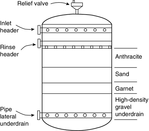
Granular multimedia filters feature layered beds of anthracite coal (0.8–1.2 mm size), sand (0.5–0.8 mm), finely crushed garnet (0.4–0.6 mm) and magnetite (0.3–0.4 mm) or other materials, as shown in Figure 2.4. The top layer of the bed consists of the lightest and most coarsely graded material, e.g. anthracite coal, whereas the heaviest and most finely graded material, e.g. garnet or magnetite, is the bottom layer. The intermediate layer is silica sand. The specific gravity of anthracite is one-half that of silica sand. A typical bed is 1 m in depth. The principle is “filtration in depth” – larger particles are removed at the top layers, and smaller ones are removed deeper in the filter media, i.e. the entire bed acts as a filter rather than the top few centimetres.
During service flow water typically flows downwards from top to bottom under pressure. Typical service superficial flow velocities (flow rates/bed cross-section area) are 7–12 m/h for single-media gravity and pressure filters, 14–20 m/h for multimedia gravity and pressure filters and 12–24 m/h for up-flow filters. Filter operation must avoid channeling and “leakage” of suspended solids; otherwise, the RO membranes will get fouled. Water space above the bed (50–100% freeboard) is provided to allow for bed expansion during backwashing.
Since suspended solids are collected on the media, regular cleaning (backwashing) is required. The rejected particles form a layer on the surface of the media and contribute to blockage of the pores in the filter medium resulting in an increase in the pressure drop (ΔP). Typically, when ΔP reaches 1 bar, the filter is backwashed. During backwashing water flow direction is reversed; it enters the bed through the bottom and flows upwards. This fluidises the bed, which along with the reversed flow, dislodges the silt and carries it to waste. The typical backwash flow rate is 24–36 m/h depending on the temperature, high enough to expand the media bed by at least 50%. The backwash cycle lasts 10–15 min and is followed by a rinse cycle that is accomplished by passing water in a down-flow direction for 5–10 min.
Sometimes coagulants are injected in the feed water line upstream of granular media filters to remove suspended matter of colloidal nature when the particulate matter is either too small or electrostatically repelled from the media. Polymeric coagulants are added in low dosages (< 10 mg/l) to remove particles down to 0.5 μm particle size as compared to 10 μm without the coagulant. Anionic coagulants have been shown to reduce the turbidity of raw water to less than 0.5 NTU at a nominal dosage of 1–2 mg/l.
2.2.4 Activated carbon filtration
Activated carbon filtration (ACF) is one of the most effective methods for removing non-polar organic compounds (low, medium and high molecular weight), precipitated iron and chlorine from water [10,12,13]. Activated carbon is a micro-crystalline, non-graphitic form of carbon, e.g. bituminous form of coal that has been processed to develop internal porosity. Activated carbon has the highest volume of adsorptive porosity of any material known to man. Because of its large surface area (1 l of granules has a surface area of 50 ha), activated carbon has a great ability to adsorb organic molecules of liquids or vapours. During feed processing, an organic molecule in the feed enters a surface pore and diffuses to a micropore where it is adsorbed on the carbon surface by physical attraction due to van der Waal’s forces. Up to 95% of organics can be reduced. The organic loading is 2–6 kg per 50 kg of carbon. Aromatic compounds are removed more effectively than aliphatic compounds, and non-polar organic compounds are better removed than polar compounds. In addition, some trace inorganics can be removed when chelated with organic compounds.
Activated carbons have specific properties depending on the material source and the mode of operation. Generally speaking, carbons from bituminous coal have a smaller pore size, a larger surface area and a higher bulk density as compared to lignite carbon. A typical surface area range is from 850 to 3000 m2/g. Bituminous coal also has a lower “peroxide number” than lignite. Peroxide number is an indicator of catalytic activity of carbon; the lower the number, the higher is the catalytic activity. Property standards used for specifying carbons for a specific application are defined below:
• The Phenol Number is used as an index of carbon’s ability to remove taste-and-odour compounds.
• The Iodine Number relates to the ability of activated carbon to adsorb low molecular weight substances (micropores have an effective radius of less than 2.0 μm).
• The Molasses Number relates to the carbon’s ability to adsorb high-molecular weight substances (pore size ranges from 1 to 50 μm).
Activated carbon is also used for removing chlorine. Chlorine manifests itself mostly as hypochlorous acid (HOCl) and hypochlorite ion (OCl−). Hypochlorous acid is the primary disinfectant, and hypochlorite ions are less effective. Hypochlorous acid is removed by reduction with carbon as per the following reaction:
Chlorine is adsorbed by carbon in the top 5–10 cm of the bed. The bed depth is typically 1 m. Since chlorine is consumed within the top few cm of the carbon bed, the media is susceptible to bacterial growth when the water temperature is greater than 12°C. A pH range of 6.5–7.5 and water temperature between 12 and 27°C provide the best environment for chlorine removal by activated carbon.
During normal service feed water flows downwards through the bed from top to bottom as in the case of GMF under pressure. The linear flow velocity is 5–10 m/h. The flow is reversed during backwash. The beds are backwashed at 7–12 m/h based on service run time or when the pressure drop across the filter bed exceeds 1 bar. The backwash cycle is followed by a downward flow rinse cycle before the bed is returned to service. Backwashing only removes the material collected on the surface of the media, and not what is adsorbed in the pores. Once the pores are filled with organics, carbon can be either regenerated or reactivated. The modes of regeneration are thermal, steam, solvent extraction, acid or base treatment, and chemical oxidation. In water treatment, thermal regeneration is usually done but weight losses and a loss of capacity result from regeneration.
2.2.5 Membrane filtration
Membrane filtration encompasses UF and MF and should not be confused with RO and NF.
In the last 15–20 years semicontinuous, semicontinuous dead-end MF/UF has emerged as a viable process for treating municipal waters and seawater prior to RO desalination [6–9].
Membrane filtration is used for treating high-turbidity waters, surface waters high in TOC and for tertiary water treatment, and provides a more stable and superior water quality than coagulation–sedimentation and media filtration. It is a simple and cost-effective alternative to conventional water treatment operations.
Membrane filtration is a highly effective barrier to particles such as suspended solids, colloidal particles, cysts and bacteria producing treated water with very low turbidity (0.1 NTU) and consistent quality irrespective of the feed source. It has proven to be very effective and reliable in removing microbiological parasites, Giardia and Cryptosporidium, since these systems were first deployed in 1995. The application has increased dramatically due to its ability to produce high-quality potable water, small footprint and relatively low cost. These systems operate at very low feed pressures (< 1–2 bar) and at relatively low trans-membrane pressure (TMP).
The UF/MF market for municipal water treatment was worth $300 M in 2006 and is projected to double by 2014 [8,17]. This market is broadly divided into three categories: (i) drinking/potable water, (ii) seawater RO/NF pretreatment and (iii) wastewater reuse. Increasingly, UF/MF systems are being used for RO/NF pretreatment instead of conventional pretreatment (coagulation, sedimentation, media filtration). High-pressure membrane systems (RO/NF) operating on UF/MF treated water are less prone to fouling, require minimal chemical treatment and have higher on-stream line. The overall result is a higher RO system throughput and longer RO membrane life.
Membrane filtration like other membrane processes is prone to severe fouling. To a large measure membrane fouling has been addressed by backwashing with water periodically; during backwash the filtered water flows in the reverse direction as shown in Figure 2.5 to dislodge the solids and restore the flux lost as a result of cake build-up on the membrane surface and clogging of the membrane pores [6,9]. However, for more challenging waters, chemical pretreatment is also required [18,19]; for example, addition of coagulants ferric chloride, ferric sulphate, alum, or polyaluminium chloride in low dosages to increase the size of suspended solids and colloidal particles to prevent or minimise colloidal, organic and/or biological fouling (see Table 6.8). Coagulation pre-treatment possibly reduces fouling by reducing pore constrictions rather than forming the gel layer since coagulants remove mostly hydrophobic compounds and very little hydrophilic neutral compounds. Coagulant addition is also required to remove TOC and tri-halomethane (THM) precursors. In the treatment of secondary effluent, both coagulation and activated carbon adsorption are effective in removing dissolved organic carbon; carbon adsorption removes both small and large organic compounds whereas coagulation removes predominantly larger molecules including biopolymers and humic substances.

Continuous cross-flow filtration
Cross-flow UF and MF systems are mainly used for applications in biotechnology, dairy, colour removal from groundwater and industrial wastewater. Industrial wastewater treatment includes electroplating rinse water processing for paint recovery, treatment of oil/water emulsions, processing wastewater containing heavy metals, oil and grease prior to effluent discharge, textile wastewater, and pulp and paper wastewater. Cross-flow UF and MF systems – mostly tubular and hollow-fibre membranes – operate in continuous mode. The feed flow is inside out, i.e. the feed flows in the tube side and the permeate flows radially out of the tube wall. Ninety percent of the reject is typically recycled back to the feed tank at a high velocity of ~ 4–5 m/s. Because of the large i.d. as is the case with tubular membranes, the membrane elements can handle feeds with solid levels of up to 5%. The process is facilitated by operating in a turbulent regime to reduce the build-up of solute cake on the membrane surface. High cross-flow velocity (turbulent flow and surface shear) and large i.d. often eliminates the need for pre-filtration. The permeate flow rate is 10–15% of the cross-flow rate at a flux of ~ 300–500 lmh. Thus, a UF/MF system, designed for 20 m3/h permeate flow rate, may require a feed/recirculation pump rated for 250 m3/h at 3–4 bar g feed pressure. Backpulsing with filtered water or permeate reduces the frequency of cleaning cycles. Overall wastewater recoveries of up to 95% are achieved. Cross-flow systems are best suited for relatively small flow systems (up to 100 m3/h) and special applications. They are not economical for treating large systems such as municipal and seawater treatment because of several drawbacks:
• High cross-flow velocity (high shear rate) means high feed/recycle flow rate resulting in high energy cost of pumping.
• Low surface area and packing density (especially tubular membranes) result in a large footprint.
• Recovery per pass is only 10%.
• Frequent chemical cleaning is required to remove or dissolve the strongly held accumulated particles that are not dislodged with backwashing.
• High Capex and Opex
Semicontinuous dead-end filtration
The most commonly used membranes for municipal water treatment are hollow fibre modules that are supplied in three operating formats: (i) pressure driven inside feed – PDI, (ii) pressure driven outside feed – PDO and (iii) submerged vacuum driven – SUBO [6,9,17]. Classification and specifications of membrane modules are detailed in Table 6.14. These UF/MF systems operate in semicontinuous dead-end mode with intermittent backwash often combined with air scour either during filtration and/or backwash cycles [9]. The flow regime typically is from outside of the fibre (shell side) through the pores in the membrane wall to the lumen side. As the water gets filtered, the solids rejected by the membrane form a layer on the membrane surface. The foulant cake layer is removed by backwashing the membrane elements by air scouring and air-assisted backwash every 30–60 min to maintain the flux (constant flux operation). Over time, chemical cleaning is required to remove traces of foulants that are difficult to dislodge by backwash. Backwashing reduces the frequency of chemical cleaning, thereby, enabling the membrane system to run on feed water with turbidity as high as 500 NTU. The filtrate or product water turbidity is typically ≤ 0.1 NTU. Since the solids content is low (< 0.5%) in water treatment applications, submerged membranes are now increasingly used instead of pressurised membranes.
Membrane bioreactors
Membrane bioreactors (MBRs) are a special application of membrane filtration and discussed in detail in Chapter 3. It is a novel process that combines a biological stage with a membrane element. In this process, biological degradation of organic pollutants is carried with microorganisms in the bioreactor followed by membrane filtration to separate microorganisms [20,21]. The use of membranes to remove solids from treated wastewater is the main difference between MBRs and conventional biological treatment plants; higher removal efficiency than conventional treatment plants, e.g. the MBR, allows a higher biomass concentration, higher COD removal (> 90%) and higher separation of solid suspensions (complete retention of the biomass). The MBR process has shown to be more efficient in removing total BOD, turbidity and coliforms. By eliminating the problem of poorly settling flocs when using a MBR system, there is more biological degradation resulting in higher treatment efficiency.
The types of membranes used in MBRs are (i) flat sheet (FS), (ii) hollow fibre (HF) and multitube (MT). There are two types of MBR technologies: (a) external MBR (eMBR) in which the membrane modules are placed outside the bioreactor (MT only), and (b) submerged MBR (sMBR) where the membrane module is placed inside the bioreactor (FS and HF) [20]. The sMBR is more economical and energy efficient: (a) there is no recycle pump since aeration generates a cross-flow across the membrane surface, and (b) the operating conditions are milder because of lower values of TMP and tangential velocity. The TMP values are 1–4 bar for eMBR and 0.5 bar for sMBR systems. The permeate flux for sMBR, however, is lower: 15–50 lmh vs. 50–120 lmh for eMBR. Polymeric MF membranes with a pore size of 0.1–0.4 μm are the main membranes used in sMBR systems while tubular inorganic membranes are generally used in eMBR units. The eMBR units are preferred to sMBR units when treating concentrated effluents or concentrated biomass to avoid membrane fouling; higher shear rate is achieved because of higher recycle flow rate.
For municipal wastewater treatment, MBR systems are economically attractive where space is limited especially in urban areas or when high effluent quality is required for water reuse. Most MBR units use submerged membrane plates or hollow fibres. Fouling by microorganisms as a result of microbial products, concentration and size of particles is one key area of process deficiency. Different strategies have been considered for controlling fouling including backwashing. In addition, there is concern whether oxygen can become the limiting factor during aerobic biological activity [20]. Since the particulate solids content in the wastewaters treated by submerged MBR systems is relatively high (e.g. TSS = 10–15 mg/l) with additional colloids and macrosolutes, bubbled cross-flow is used to minimise concentration polarisation and subsequent fouling [9].
2.2.6 Deaeration-decarbonation
Air stripping is used to remove oxygen, carbon dioxide, ammonia and volatile organic compounds (VOCs) from water. Decarbonation removes alkalinity – carbonate, bicarbonate, carbon dioxide – by acidification and stripping the resulting carbon dioxide. Carbon dioxide is removed from RO product water to reduce the load on ion exchange resins downstream. Stripping of carbon dioxide increases the water pH, and thus reduces the corrosive properties of water. Forced air decarbonation is always used in conjunction with either RO or IX.
Ammonia is easily stripped since it is volatile. When the pH of water is raised above 9.3, the equilibrium point, ammonium ions in water convert to ammonia as per Equation (2.15) given below as the equilibrium shifts to the left. The pH range for stripping ammonia is 10.8–11.5:
In the case of stripping VOCs such as halogenated hydrocarbons that are carcinogenic, the process relies on the tendency of moderately soluble organic compounds to vaporise based on Henry’s law.
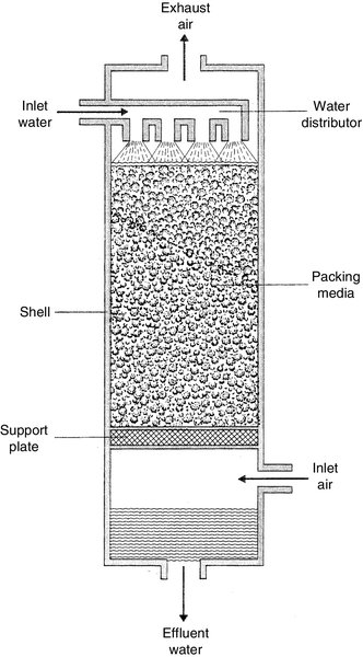
Air stripping requires packed towers for maximum operational efficiency [13]. Water is pumped to the top of a tower packed with media as shown in Figure 2.6. The water is evenly distributed across the media. As it flows down under gravity it forms a film layer on the packing surfaces. Air is blown upwards from the bottom contacting the large surface areas. The blown air enhances the removal of the volatile species by mass transfer. Degasification is usually not economical if water alkalinity is less than 100 mg/l or 20% of total anions, or if the water flow rate is less than 5–6 m3/h. The ratio of gas to liquid is in the range of 100–1 (volume basis).
2.2.7 Chemical oxidation
Chemical oxidation is used to control inorganics (manganese, ferrous iron, sulphur, sulphite and cyanide irons) and organics (phenols, amines, humic acids, toxic compounds, bacteria and algae) by converting them to unharmful products [10]. The oxidising agents used include air, oxygen, ozone, hydrogen peroxide, chlorine, chlorine/hypochlorite and chlorine dioxide. Aeration followed by chlorination is very efficient at precipitating sulphur, which can then be removed via filtration. Contact times of 3–4 h can reduce the hydrogen sulphide levels by up to 3 ppm via aeration alone. Hydrogen sulphide is generally found in well water, particularly shallow wells. Chlorination increases the kinetics of precipitation, and at the same time acts as a germicide to minimise the growth of sulphur bacteria, which are the source of hydrogen sulphide. Chlorine, potassium permanganate and ozone are also effective in destroying many odorous compounds.
Manganese greensand oxidation-filtration
Some well waters, usually brackish waters, contain divalent ferrous iron, manganese and sometimes sulphide in the absence of oxygen. When water is exposed to air or is chlorinated, these compounds are oxidised resulting in the formation of insoluble colloidal hydroxides and elemental sulphur as [12,14]:
The manganese greensand filtration (MGF) process employs manganese greensand as the filter medium to remove soluble iron, manganese and hydrogen sulphide by one-step oxidation filtration. The filter bed consists of anthracite filter media over manganese zeolite (greensand). Greensand is processed from glauconite, which is an iron potassium alumino-silicate material of marine origin. The filter-bed material acts as a catalyst for the reaction of iron with oxygen. It can supply the necessary oxygen, which must be replenished with an oxidising regenerant solution such as potassium permanganate (KMnO4).
The most common method of oxidative MGF is known as continuous regeneration. Permanganate solution (1–2%) is injected into the raw water feed water line. Precipitation of iron and manganese occurs in the anthracite bed as per the reaction in Equation (2.19). Heavier precipitates are filtered out in the anthracite bed, and the remaining fines and residual dissolved metal are removed by greensand. The water pH should be about 7.2.
Iron concentrations up to 15 ppm can be effectively removed, although concentrations greater than about 3 ppm require low service flow rates, which results in short runs between the backwash cycles. At low feed water iron concentrations, the flow velocity is 14–20 m/h for up to 36 h between the backwash cycles. Lower flow velocity 4 m/h and shorter service run lengths are advised when the feed water iron concentration is 3–15 ppm.
2.2.8 Disinfection
Disinfection of RO/NF feed water is required to prevent biofouling of the membranes. However, the disinfected water must be treated with reducing agents if the membrane polymer, e.g. polyamide is damaged by oxidants. Disinfection is the selective destruction of pathogenic organisms (bacteria and viruses). Recently, microconstituents such as endocrine disrupting compounds as well as pharmaceutical and personal care products have also come under review. Disinfection is not the same as sterilisation, which implies the destruction of all organisms. Disinfection treatment methods commonly used include (a) chlorination or ozonation chemical means, (b) photochemical means, e.g. ultraviolet disinfection and (c) physical means such as membrane filtration. Parasites such as Giardia lamblia and Cryptosporidium parvum are resistant to conventional forms of disinfection such as chlorination, but are removed by other methods such as ozone, ultraviolet irradiation, and membrane filtration.
Chlorination
The disinfectant action of chlorine results from its strong oxidising action on bacterial cell’s chemical structure that destroys the enzymatic processes required for life [12]. The effectiveness of chlorine disinfection is a function of the product of contact time and chlorine residual. Chlorine gas is soluble in water (7160 mg/l at 20°C and 1 bar), and hydrolyses rapidly to form hypochlorous acid or as the hypochlorites of sodium and calcium:
Hypochlorous acid (HOCl) dissociates in water to hydrogen ions and hypochlorite ions (OCl−). The sum of Cl2, NaOCl, Ca(OCl)2, HOCl and OCl− is referred to as “free available” chlorine. The power of free chlorine residual decreases with increasing pH. Hypochlorous acid concentration at 20°C is 90% at pH 7, 50% at pH 7.6 and 10% at pH 8.6. Almost the reverse is true for hypochlorite ions. Hence, automatic monitoring of residual chlorine and automatic feedback of injection rate is necessary to prevent over-dosage or inadequate disinfection. Minimum chlorine residuals for bactericidal disinfection after 60 min of contact vary between 1 ppm at pH 6.0 and 1.8 ppm at pH 8.0. A hypochlorous residual of 0.5–1.0 ppm is effective within 30 min.
In gaseous form chlorine is extremely hazardous. Liquid chlorine is shipped in pressurised steel cylinders. One volume of liquid chlorine yields about 450 times vapour volume. Because of safety concerns liquid chlorine compounds such as sodium hypochlorite are used instead. Sodium hypochlorite (NaOCl) is handled in liquid form at concentrations between 5 and 15% available chlorine. Calcium hypochlorite [Ca(OCl)2] contains about 70% available chlorine.
An alternate technique is on-site generation of NaOCl, which is achieved through electrolysis by applying an electrical current to a solution of salt (preferably food-grade) and water. The electrolytic cell is the heart of the oxidant producing unit. The cell consists of two electrodes placed so that both make contact with the water and brine solution. A by-product of the electrolysis reaction is hydrogen gas, which is safely removed from the cell and the oxidant storage system. On-site generators are used to provide disinfection for swimming pools, cooling towers and sanitation for clean-in-place operations. The largest application of on-site NaOCl generators is for municipal drinking water disinfection.
Ozonation
Ozone is a strong oxidant and disinfectant. It has similar bactericidal properties to chlorine and is at least equal to chlorine in its ability to perform virus inactivation [12]. Ozone is also an option for odour control in reclaimed wastewater treatment. Ozone oxidises organic contaminants via a reaction with molecular ozone (O3) or through a reaction with the hydroxyl radical (OH•), which is formed often in the presence of a catalyst when ozone is added to water. Ozone is generated on-site from air or oxygen zone when a high voltage is imposed on a discharge gap. It is generated on-site because it is a relatively unstable gas with a half-life of about 10 min. When ozone is added to water, it rapidly reverts to oxygen so that no chemical residuals remain in the ozonated water. Chlorine is added for post-disinfection, if required. There are, however, some adverse health effects due to the formation of bromates and aldehydes as by-products. The maximum allowable limit of bromate, a carcinogen, in drinking water is 25 ppb (μg/l).
UV irradiation
Ultraviolet (UV) light represents a band of electromagnetic light in the 100–400 nm range. It is a non-chemical disinfectant process that uses a very short contact time (< 5 s). UV light is used to break specific chemical bonds, sometimes by direct photolysis, but usually by the creation of highly reactive hydroxyl (OH-) radicals. Photolysis applications include dechlorination, de-ozonation, removal of TOC and more recently to counter the threats caused by endocrine disruptors and pharmaceutical compounds (both metabolised and un-metabolised).
UV disinfection avoids a major disadvantage of chlorination, i.e. the generation of harmful by-products such as trihalomethanes. UV disinfection ensures that the drinking water is free from pathogens such as e-Coli, Legionella and Cryptosporidium. UV is also extensively used in manufacturing processes such as bottled water, beer, carbonated soft drinks and ultrapure water. Disinfection by UV radiation involves damaging the genetic material of organisms by energy in the form of light of wavelength 254 nm emitted from a low-pressure mercury vapour lamp [12]. This particular wavelength alters the genetic material (DNA) of bacteria, viruses and other microorganisms. With their DNA altered, they are unable to reproduce and die within minutes. The dead bacteria produce TOC.
For microbial destruction, 254 nm UV energy is used, whereas shorter (and more powerful wavelength) electromagnetic radiation, 185 nm UV energy, is used to reduce organic compounds and chlorine destruction. The energy of a light beam is inversely proportional to the wavelength. Thus, 185 nm UV irradiation carries more energy and is more powerful than the 254 nm light; 185-nm energy oxidises total oxidisable carbon (TOC) to form carbon dioxide and water. Most microorganisms are damaged at a UV irradiation dosage level of 10,000–30,000 μW-s/cm2, whereas the dosage level required for reducing ozone, chlorine and TOC reduction is 90,000 μW-s/cm2.
UV systems generally consist of a reactor with a number of lamps that emit UV radiation. Each lamp is encased in a quartz tube. As the water flows thorough the lamps, it gets radiated. Polytetrafluoroethylene (PTFE) is also used since PTFE is transparent to UV radiation. UV radiation dosage is determined by residence time in the reactor and the intensity of radiation. The effectiveness of a UV system depends on the hydraulic design of the reactor, absorbance of liquid, presence of particles and transmittance of the lamps and the quartz tubes. Intimate contact between the liquid and the lamps needs to be maintained at all points in the reactor since radiation diminishes with distance. Contact time for radiation exposure is maximised by maintaining plug flow in the reactor and by creating turbulence to cause transverse dispersion. The UV lamp's intensity typically drops to 60% in a year or after 8000 h of use.
2.2.9 Electrocoagulation
Electrocoagulation (EC), a radio frequency technology developed 100 years ago, is a simple and effective technology for treating a wide range of waters including municipal water and industrial wastewaters prior to membrane treatment [22–24]. The EC reactor is an electrochemical cell. EC involves the generation of coagulants in situ by dissolving aluminium or iron electrodes; the generation of metal ions takes place at the anode and hydrogen is generated at the cathode as an electrolysis product. Hydrogen helps to float the flocculated particles out of water. The electrodes are arranged in a mono-polar or bi-polar mode. The electrodes are in plate form or in packed form of metal scraps. The reactions occurring in an EC reactor are shown schematically in Figure 2.7.

The electrolytic dissolution of Al anode in water produces:
![]()
and, water decomposition at the cathode produces hydrogen bubbles:
![]()
The overall reaction for Al dissolution at the anode is:
Similarly, the electrolytic dissolution of Fe anode in water produces:
![]()
The metal ions, Al3 + (or Fe2 +), are very efficient coagulants for flocculating particulates. Aluminium is usually used for water treatment and iron for wastewater treatment because iron is relatively cheaper. Faraday’s law can be used to calculate the amount of coagulant produced [22]:
where m is the mass of Al generated, F is Faraday’s constant (96,486 C/mol), I is the operating current in Amps, t is run time, M is the molecular weight of aluminium in g/mol and z is the number of electrons transferred in the anodic dissolution (z = 3 for Al).
Operating parameters
The quality of treated water depends on the amount of ions produced (mg) or charge loading (A h), i.e. current and time. The supply of current determines the amount of Al3 + (or Fe2 +) released from the respective electrodes. A large current means a small EC unit. However, a very high a current usually results in wasting electrical energy in heating water. The optimum current density for EC is 20–25 A/m2. However, the current density value should take into account other operating parameters such as pH, temperature and flow rate to ensure high current efficiency.
The optimal temperature for operating the system is 60°C resulting in lower energy consumption as a result of higher conductivity than at ambient temperature. Higher water conductivity, for example, with the addition of table salt (NaCl), is beneficial as it results in reduced power consumption. Besides its ionic contribution in carrying the electric charge, chloride ions can significantly reduce the adverse effects of bicarbonate and sulphate ions; HCO3− and SO42− ions can result in the precipitation of Ca2 + and Mg2 + ions forming an insulating layer on the surface of the electrodes resulting in reduced current efficiency [23]. Further, electrochemically generated chlorine is effective in water disinfection.
Treated waters
EC is effective in water treatment for drinking water supply, membrane pre-treatment, marine operation, and boiler water supply for small systems. It is very effective in treating colloids found in natural water by reducing turbidity and colour as well as removing suspended solids, oil and grease, iron, silicates, humus and microorganisms. A comprehensive summary of pollutants removed by EC is given in [24].
2.2.10 Ion exchange
The primary function of the ion-exchange (IX) operation is to remove ions from a dilute solution and concentrate these into a relatively small volume. An IX reaction may be defined as the reversible inter-change of ions between a solid phase (the ion exchanger) and a solution phase, the ion exchanger being insoluble in the medium in which the exchange is carried out [15]. IX resins remove undesirable ions by replacing them with an equivalent number of desirable ones. For example, a cation resin (R) selectively removes calcium ions by the following reaction:
The reaction is reversible; when the resin becomes saturated with calcium it can be regenerated with a concentrated solution of sodium chloride. This is known as sodium-cycle cation exchange.
IX resins
Most IX resins are based on a styrene-divinylbenzene copolymer, which is appropriately treated to graft on ionic or functional groups. For example, sulphonation produces a cation resin, while amination produces an anion resin [15].
Strongly acidic cation resins
These resins have a sulphonic acid (–SO3) functional group as shown in Figure 2.8. The ones in the H-form (–SO3H) are capable of removing all cations from water. For most deionisation applications, SAC resin with an 8% divinylbenzene (DVB) content are used. Generally, they show maximum selectivity for trivalent ions, followed by divalent and monovalent ions. They are regenerated with strong acids, usually HCl or H2SO4, and require 200–300% of the theoretical stoichiometric quantity. When used in the hydrogen cycle, the effluent is acidic. The maximum operating temperature of the resin is 135°C.

Weak acid cation resins
This class of cation-exchange resin is typified by the carboxylic acid (–COOH) functional group, which in its acid form is only very weakly ionised, e.g. methacrylic-divinylbenzene, –R′C(CH3)COOH. The degree to which dissociation occurs is highly pH dependent, increasing with increasing external pH. The resins are used for removing alkaline hardness as discussed under “softening.”
Strongly basic anion resins
There are two types of strongly basic anion (SBA) resins: Type I and Type II. Type I resin has the highest basicity, and, therefore gives the optimum effluent quality. Type II has a lower basicity and, therefore, requires less caustic for regeneration. In general, Type II resin is used where silica effluent quality is not critical. Both resins are usually based on styrene DVB; however, recent resins now include acrylic materials. The functional group in Type I is quaternary benzyltrimethyl ammonium chloride, RCH2N ⋅ (CH3)3+⋅ Cl−, and the functional group in Type II class is RCH2N⋅(CH3)2(C2H4OH)+⋅ Cl−. These resins are capable of removing all anions from water. Selectivity is maximum for divalent ions. SBA resins are regenerated with a strong alkali such as caustic soda. The maximum operating temperature of SBA resin is 60°C (OH− form) and 77°C (Cl− form).
Weak base anion resins
The WBA resins come in two forms: free base form, CH2N(CH3)2, and chloride form –CH2N(CH3)2 +Cl−. WBA resins operate essentially as acid absorbers. They are more efficient than strong base anion resins for removing free mineral acids (FMAs) such as HCl, H2SO4 and HNO3, but are not effective at removing carbon dioxide or silica.
Resins selection
Other than the selection of appropriate resin type (cation or anion) and its strength (strong or weak) there are no firm rules, and experience outweighs all other considerations. Guidelines concerning the options related to matrix, structure and particle size grading are provided by resin manufacturers. Cost is also a major factor. Matrix-modified resins (acrylic) and structure modified materials (macroporous) can increase resin cost between 20 and 150% compared with standard gel styrenic products when comparing anion or cation resins, respectively.
Physical characteristics
The size and range (0.3–2 mm) of resin beads is an important consideration vis-à-vis performance. Uniform beads have been developed to produce stronger resins that resist attrition and eliminate cross-contamination of the resins during backwashing in mixed-bed systems. Uniform size is important since it imparts [10,15,16]:
• Lower ionic leakage
• Cleaner separation of resins during mixed-bed regeneration
• Faster rinsing
Diffusion of ions into and out of a large bead limits its performance. Hence, the diffusional path length should be as short as possible to achieve:
• Increased utilisation of the functional sites located within the bead
• Higher efficiency with which regenerating solution chemicals get into and out of the bead
Limitations
The basic limitation of an IX resin to remove and exchange ions and concentrate them within its structure is determined by the “selectivity” and the “capacity” of the resin. The ions being exchanged compete for the exchange sites with the resins having a different affinity for each type of ion. Note that since IX resins are primarily designed for removing soluble ionic species, they cannot be expected to absorb macro- or colloidal ionic species except at the surface of the particle.
Demineralisation
There are two types of resins involved in deionisation water treatment applications. These are strongly acidic cation-exchange resins and strongly basic anion-exchange resins. If the regenerating solution was a strong acid, such as hydrochloric or sulphuric acid, instead of a salt, the metallic ions would be replaced with hydrogen, and the resin would then remove cations, replacing them with hydrogen ions. This is called hydrogen-cycle cation-exchange. Thus,
Anions are exchanged in a similar fashion. Anion resins usually operate in either the hydroxide cycle (regenerated with a strong alkali) or the chloride cycle (regenerated with sodium chloride):
By using hydrogen-cation and hydroxide-anion resins in series, all cations are replaced with H+ ions and all anions with OH− ions; the result is pure water. This process is called deionisation or demineralisation.
Dual-bed demineralisation
In a two-stage or dual-bed IX demineralisation process, raw water is first passed through a SAC exchange resin bed in the hydrogen form. The effluent from the cation column is then passed through a strongly basic anion-exchange resin bed in the hydroxide form. Across the cation exchanger, all cations exchange for hydrogen ions to give a dilute acidic effluent (“free mineral acids” or FMAs) made up of acid sulphates, nitrates, and chlorides together with dissolved carbon dioxide. Upon passing through the anion exchanger, neutralisation of the FMAs occurs through the exchange of all anions for hydroxide to give deionised water. A typical IX vessel is shown in Figure 2.9 (left). Dual-bed sample design calculations are given in Chapter 6.
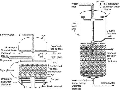
Mixed-bed ion exchange
A mixed-bed (MB) contains a uniform mixture of strong acid and strong base (Type I) resins in the H+ and OH− forms, respectively. Demineralisation occurs through simultaneous exchange of cation and anions in a single vessel. In effect, this is equivalent to having an infinite series of two-bed demineralisers in series. Every anion bead reacts instantly with the acid produced by a neighbouring cation bead, removing the acid as it forms and driving the reaction to complete demineralisation. A pictorial drawing of a MB vessel is shown in Figure 2.9 (right).
The development of the MB-IX system is considered to be the most important contribution to the application of IX technology since the development of IX resins. The key to the successful operation of the mixed-bed is the ability to separate the two resins after the service cycle so that they can be regenerated separately. Uniform beads have been developed to produce stronger resins that resist attrition and eliminate cross-contamination in separation of the resins from one another during backwashing. Not only is cross-contamination of the resins undesirable from the obvious loss of capacity, but it can also reduce the quality of water. One way to reduce cross-contamination occurring at the interface distributor is by the use of an inert resin. The inert resin has a specific gravity intermediate between those of the anion and cation resins that, hydraulically, classifies between the anion and cation resins when backwashed. The quantity of the inert resin (10–15% of total resin volume) should be enough to cover the interface distributor, thereby, effectively reducing the cross-contamination problem.
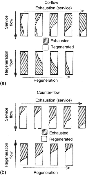
Normal operation
An IX vessel is designed to distribute influent water evenly over the resin bed so that it passes through the bed uniformly. This ensures that the bed remains in a packed condition. Disruption of the bed during service would increase the amount of impurity allowed through (called slippage), and reduce the resin bed’s operating capacity. In down-flow service, those ions for which the resins have the strongest affinity or selectivity are held at the top of the bed, i.e. those with the lowest selectivity are displaced from the exchange sites by other ions and move down the bed. When the exchange front eventually reaches the bottom of the bed as shown in Figure 2.10, the vessel is taken off line for regenerating the resins. The first sign of column breakthrough or ionic leakage is indicated by the most loosely held ions, silica (HSiO2−) for anion resins and sodium (Na+) for cation resins.
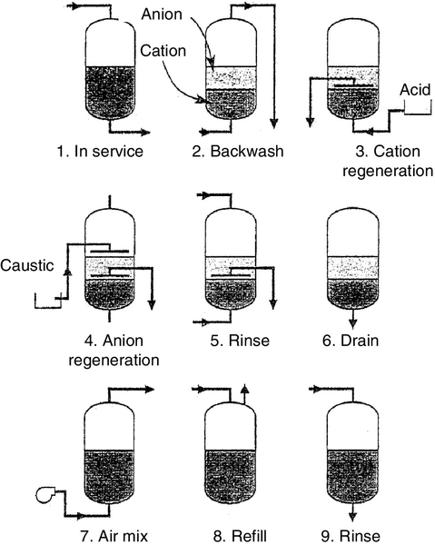
The operation of a MB is similar to a single-bed IX operation. The regeneration cycle shown in Figure 2.11 is, however, complex. Backwashing, in addition to cleaning as discussed above, helps to classify the resin: the lighter anion beads rise to the top of the bed, the heavier cation beads dropping to the bottom. An inert resin bed with intermediate density forms a layer between the two resins helping to separate them during regeneration and reduces likely cross-contamination of resins. Acid solution flows through the bottom and upward through the cation resin bed and out through the interface collector. Caustic soda solution is introduced above the bed level and flows down through the anion resin bed and out through the interface collector. The resins are then rinsed as described above and mixed with air or nitrogen before returning to service. The regeneration process is described in detail in Chapter 4.
Regeneration
Step I – Backwashing. This is accomplished by passing water upward through the bed for 10–20 min at a velocity of 7–15 m/h sufficient to expand the bed by 50–100%. Backwashing removes particulate matter, relieves any bed compression, and allows trapped gases to escape.
Step II – Chemical regeneration. Regeneration displaces the ions that were exchanged during the service run, returning the resin to the original ionic form. This is accomplished by using solutions of sufficient strength (e.g. 8–10% NaCl for softener cation resin) to drive the equilibrium established during operation in the reverse direction. Cation-exchanger resins are regenerated with strong acids such as H2SO4 and HCl. Regeneration with H2SO4 is usually done at two different concentrations; initially at 2–3% acid followed by 5–6% dilute acid. Anion-exchanger resins are regenerated with NaOH at 4–5% dilute caustic soda solution.
The regenerating solution flow rate is low enough (2–4 m3/h m3 of resin) to allow the chemical to diffuse into the resin and to allow the largest impurity ions to migrate out of the resin. Regeneration efficiency can sometimes be improved, significantly, by heating the regenerating solution. Heating caustic soda to 49°C aids in removing polymerised silica from SBA resins.
Step III – Rinsing. Excess regenerating chemicals from the resin bed are flushed by a two-step rinsing process. The first step is a displacement (slow) rinse, in which the flow rate is the same as that used for adding the regenerant solutions (typically replacement of two bed volumes). This ensures that the chemicals are fully utilised. The second step is a fast rinse, typically 10 min. The high flow rate of water during rinsing flushes out any traces of the regenerant solution.
2.2.11 Non-DI water ion-exchange applications
Besides DI water treatment and oxygen removal, there are several other applications where IX is used. Some of these applications are reviewed briefly.
Organics removal
Organic matter in surface water is supposed to behave as a colloid, and is often complexed with silica and heavy metal ions such as iron, aluminium and manganese. In order to minimise the risk of organic fouling, SBA resins operating on a co-flow chloride cycle are often employed. It is not essential that the resin has a high ion-exchange capacity. Rather, it is more desirable that they possess greater porosity even at the expense of capacity. Typically, 50–70% of organics are removable.
Nitrates removal
Biological denitrification and IX are the processes used for removing nitrates from contaminated groundwaters when present in carcinogneic concentrations (> 50 mg/l). Ion exchange is the easiest and most economic. The process uses SBA resin bed in either co-flow or counter-flow arrangement. To ensure reliable operation nitrate-selective resins have been developed. Regeneration is carried out using NaCl solutions.
Industrial wastewater treatment
SAC and SBA resins are typically used to treat wastewater effluents from metal finishing processes such as plating and anodising, pulp and paper manufacture, chemical leaching, zinc smelting, metal pickling and photographic processing plants. For example, in metal pickling where hydrochloric acid is used in the steel galvanising process, cation is removed as a complex anion. Strong base anion resins in the chloride form readily take up the chloro-complex ions (![]() and
and ![]() ), thereby rejuvenating hydrochloric acid. Similarly, SBA resins and sometimes chelating resins are used for recovering heavy metals from various process streams.
), thereby rejuvenating hydrochloric acid. Similarly, SBA resins and sometimes chelating resins are used for recovering heavy metals from various process streams.
Carbohydrate refining
IX processes in carbohydrate treatment are used for the purification of juices and syrups from cane sugar, beet sugar and corn starch hydrolysates. The main operations are decalcification (softening), deashing (demineralising) and decolourising (removal of organic colour bodies). These processes improve the yield and quality of the final recrystallised sugar or concentrated syrup. One interesting application is the inversion of sucrose to invert sugar (fructose + glucose) using SAC resins in the hydrogen form. Since raw sugar processes yields a fairly viscous syrup, macroporous resins are often used in sugar refining. Decolourising is usually done with macroporous WBA resins.
Pharmaceutical processing
IX is widely used to concentrate and recover antibiotics and vitamins from fermentation broths. For example, streptomycin molecule, which is moderately basic, is very favourably exchanged by the sodium form of macroporous WAC resins. General categories of biological compounds that are recovered and purified by IX include antibiotics, vitamins, nucleotides, amino acids, proteins, enzymes and viruses.
2.2.12 Membrane degasification
Membrane contactor (MC) is a new type of phase-contacting device for use in gas transfer and liquid/liquid extraction processes, as discussed in Chapter 1. MCs are used for stripping (degassing) dissolved gases including oxygen and carbon dioxide from deionised water and many high-purity water industrial applications where deaeration towers are not suitable because of possible contamination [25]. The CO2 level is reduced to 1–5 ppm. Because of their compact size, MC systems are easily integrated with a separation process such as RO or IX, providing a highly efficient hybrid system. They can also be used in aerobic wastewater treatment without bubble formation. The process flow sheet of a MC unit with typical operating conditions for removing O2 is shown in Figure 2.12.
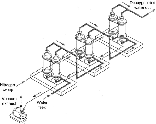
Because of the large surface area of the fibres, a MC module can provide a large number of separation stages in a relatively short length of the module; the size of an MC is more than an order of magnitude smaller than a vacuum tower degasifier with comparable capacity. In general, it is the large surface area per module and not the enhanced mass transfer that makes the process more attractive than conventional contactors. In addition to being very compact in size, MC can be operated over a wide range of flow rates and outlet oxygen specifications. Because of its modular design, a membrane degasifier system can be expanded by adding MC modules in either series or in parallel. Adding more in series allows for lower oxygen concentration in wateroutlet values, while additional units in parallel allows for higher flow rates.
For a given MC, the performance can be described as a function of liquid flow rate. The performance of an MC is based on the percentage of oxygen removal (OR) defined as:

2.2.13 Electrodeionisation
Electrodeionisation can be referred to as “electrodialysis moderated ion exchange.” An EDI cell consists of MBIX resins sandwiched between an anion-exchange membrane (AEM) on one side and a cation-exchange membrane (CEM) on the other side, as shown in Figure 2.13 [26]. Electrodialysis (ED) is generally used to reduce the salt level from 1000–10,000 mg/l to a few hundred mg/l, whereas EDI is used to purify solutions containing 10–100 mg/l down to < 1 mg/l. In the production of high-purity water, salt concentration in product water has to be reduced to the ppb (μg/l) range. This is not possible with ED because of the low conductivity of very dilute feed stream. This limitation is overcome by filling the diluate chambers with MBIX resin beads. The ions in the chamber partition into the IX resin beads and get concentrated several times so that ions and current flow through the beads, resulting in much lower resistance of the cell than in a normal cell operating with the same very diluate feed.
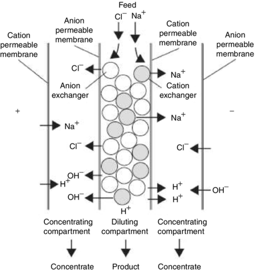
An EDI module consists of multiple cell pairs (up to 240 cell pairs) stacked end-to-end. The resin spacers in thick cells are 8–10 mm and 3 mm in thin cells. DC power is applied to a positive electrode (anode) located on one end of the module and to a negative electrode (cathode), located on the other end. The IX membrane is ion selective, which means that the CEM allows only cations to pass through, and AEM allows only anions to pass through. Since the polymer is hydrophobic, it is not permeable to water. Feed water enters the product compartments in parallel, and flows from top to bottom. The product stream flow rate may be increased or decreased within the range given in the specifications to meet the changing usage requirements. Increasing the product water flow rate above the specified range decreases the product water quality. There are two modes of operation: constant voltage and constant current.
Because of the direct current that is applied perpendicular to the flow by the electrodes, the anions are driven toward the anode through the selectively permeable AEM. Similarly, the cations are driven toward the cathode through the CEM. The ions in the reject compartment are swept out of the module and sent to drain. As the water travels through the product compartments, it becomes increasingly pure. The DC voltage causes some of the deionised water towards the bottom of the product compartments to “split,” i.e. the water molecules are broken down into hydrogen (H+) and hydroxyl (OH−) ions. The H+ and OH− ions react to regenerate the mixed-bed resins at the bottom of the compartments continuously, thus, producing highly pure water. As a result, the EDI system has the advantage of being environmentally friendly because chemicals are not needed to regenerate the resin. Further, EDI is more effective than MBIX for removing weakly ionised ions boron and silica.
EDI units are designed to operate with little or no downtime. EDI produces a consistent quality water without the problems and costs of regenerating IX resins and waste neutralisation [25,26]. High-purity water of up to 16.0 MΩ-cm resistivity can be produced with an EDI system using RO permeate of conductivity 1.0 μS/cm as feed water with product water recoveries in the 90–95% range. The following operational parameters can help to maximise the recovery of EDI units [27]:
• Use sodium cycle IX softeners instead of anti-scalants for RO pre-treatment; lower hardness leakage through the RO and less chance for upsets allows the operation at higher recovery.
• Lower alkalinity and CO2 loading to the EDI by operating the RO at high pH (> 9.0). This requires softened feed water to prevent scaling of RO membranes.
• CO2 is not rejected by membranes and is transferred to the EDI reject. When the reject is recycled to the RO inlet, the pH of RO feed water is raised to > 9.0 with caustic soda required to convert CO2 to sodium bicarbonate, which is rejected by the RO membrane.
• If CO2 concentration is > 5.0 ppm, the feed water should be degasified using MCs to prevent build-up of CO2 in the system, which lowers product water recovery and efficiency. Alternately, raise the pH of RO feed water to > 9.0.
Feed water temperature, hardness, alkalinity, free chlorine and pH must meet the EDI quality requirements given in Table 2.3. RO pre-treatment is essential. In critical applications where bacteria control is important, a bacteria destruct 254 nm UV light is installed to reduce the bacteria count in EDI feed water. EDI modules are sanitised with chemicals or preferably hot water at 80°C.
Table 2.3
EDI process feed water requirementsa
| Item | Process condition |
| Pressure | |
| Minimum | 2 bar g |
| Maximum | 7 bar g |
| Temperature | |
| Minimum | 10 °C |
| Maximum | 45 °C |
| pH | 4–10 |
| Free chlorine | < 0.02 mg/l (intermittent) |
| Iron, manganese, sulphide | < 0.01 mg/l |
| Silica | < 2.5 mg/l at 90% recovery |
| Total hardness | Depends on alkalinity and recovery; < 1.0 mg/l at 90% recovery |
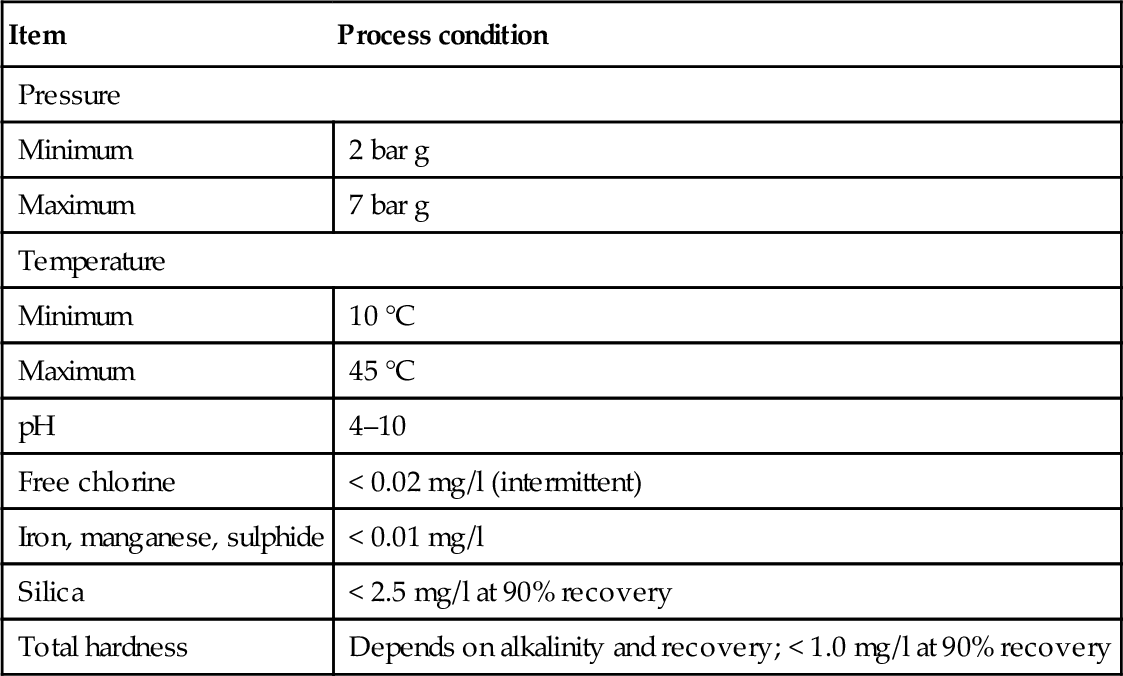
Source: USFilter/Ionpure.
a The total hardness, CO2 and alkalinity of feed water determine the maximum recovery (yield) at which the EDI unit may be safely operated without damage to the module.
Electrodeionisation has made major advances since it was introduced 25 years ago. It has captured a niche market for polishing RO product water in high-purity water applications. There are several thousand EDI systems in commercial operation for the production of high purity water ranging from < 0.1 to > 1500 m3/h. Commercially available devices are produced in two main configurations, plate-and-frame and spiral-wound [25,27]. More than 90% of installed EDI systems are plate-and-frame type. The plate-type devices are similar in concept to a plate-and-frame heat exchanger, with multiple fluid compartments sandwiched between a set of endplates (and electrodes) that are held in compression by bolts or threaded rods. The spiral EDI devices are analogous to a spiral-wound RO element, but with the ion-exchange membrane, resins and spacers wound spirally around a centre electrode rather than a permeate tube [25,27].
Newer EDI designs based on fully-filled compartments – electrode, diluting and concentrating compartments filled with MBIX resins – have been studied [28,29]. In order to increase the removal of weak acids and bases such as boric or silicic acid, alternate module design using bipolar membranes and separate compartments for anion-exchange and cation-exchange resins as shown in Figure 2.6 have also been investigated [29]. While EDI with separate IX resin beds and bipolar membranes leads to an effective removal of weakly dissociated acids, there is still a problem with contamination of the product water by diffusion of cations from the concentrate through the AEM into the diluate when the AEM are not completely permselective. This limitation can be overcome by including a “protection compartment” filled with an anion-exchange resin and rinsed with a small portion of the diluate [29].
2.2.14 Post-treatment of desalinated water
Desalinated water (RO permeate) is generally acidic (pH ~ 6.0), chemically unstable, low in mineral constant and corrosive. Water that contains no hardness is considered unhealthy for potable use, and water that contains no dissolved oxygen may taste flat. Hence, remineralisation is necessary to equilibrate the water to prevent corrosion in pipelines and to re-introduce some ions essential for human health. The permeate can be remineralised in several ways: calcite contactors, lime coupled with carbonic acid solution, sodium hydroxide and blended phosphate corrosion inhibitor, and permeate blended with raw groundwater [30].
Calcite treatment is simpler and cheaper than dosing with sodium hydroxide. RO permeate passes through a packed calcite bed and the medium slowly dissolves over time. Calcite dissolution is produced according to equation:
The dissolution increases alkalinity (HCO3−) with the added benefit of increasing an equivalent amount of hardness (Ca2 +). Limestone is a sedimentary rock primarily composed of calcite, aragonite and vaterite. Calcite can be pure in composition (CaCO3) or can contain low concentrations of magnesium-forming magnesium calcite. Natural limestone can contain minerals or impurities such as dolomite [CaMg(CO3)2] and quartz (SiO2). The remineralised water is disinfected typically with chlorine, sodium hypochlorite or chloramines. It may include fluoride replacement as well.
2.3 Membrane Fouling, Scaling, and Controls
One of the limitations of membrane processes for liquid separations is severe loss of productivity due to concentration polarisation and fouling as discussed in Chapter 1. The drop in flux can be as much as 80% in a few minutes or may take days. The loss of productivity is substantial vis-à-vis membrane permeability measured with water. Sources of membrane fouling and scaling are detailed in Table 2.4. Common pre-treatment processes discussed in this chapter are summarised in Tables 2.2 and 5.1.
Table 2.4
Sources of membrane fouling and scaling
| Substance | Extent and/or mechanism |
| Fe, Mn, Al hydroxides | Severe fouling, rapid kinetics |
| Mineral saltsa | Form mineral scales when their solubility is exceeded |
| Colloids | Electrically charged; SDIb and zeta potential determine fouling |
| Microbiological | Forms a biofilm gel layer |
| Proteins | Fouling by hydrophobic and charge interactions |
| Polyelectrolytes | Fouling by charge interaction |
| Organic acids | Humic and fulvic acids cause severe fouling |
| Oil and grease | Hydrophobic membrane fouling |
| Suspended solidsc | Cannot exceed 0.5 ppm |
a CaCO3, CaSO4, BaSO4, SrSO4.
b Silt Density Index.
c Applicable to RO/NF.
Scaling is largely due to the deposition of materials in close proximity to the membrane surface that often results in fouling [31,32]. One problem with scaling in membrane systems is that the process introduces a large amount of potential foulants in the system; for example colloidal fouling occurs if total suspended solids (TSS) are too high. Cakes of colloids formed on the membrane surface result in blinding the membranes, reducing the flux drastically in most cases, as shown in Figure 2.14. Thus the efficiency of a membrane system, especially the life of a RO or a NF membrane (RO and NF membranes are less rugged than UF and MF membranes), depends on effective treatment of the membrane system feed water.
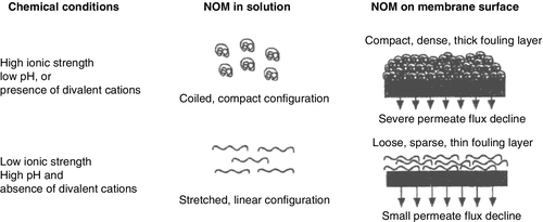
Generally speaking, fouling and scaling problems are spread as follows: (a) organic fouling – 50%, (b) colloidal fouling – 30% and (c) mineral scaling – 20%. The effects of these on membrane performance are given in Table 2.5. Organic fouling consists of biofouling, natural organic materials such as humic and fulvic acids and organics added during pre-treatment – coagulants and anti-scalants. Colloidal fouling occurs in almost all membrane systems, and is the most serious of the fouling problems.
Table 2.5
Effect of fouling and scaling on membrane performance
| Type of fouling | Permeate flowa | Feed pressure | NDPb | Solute passage |
| Organic | Loss | Increases | – | – |
| Colloidal | Loss | Increases | – | Increases |
| Scaling | Loss | – | Increases | Increases |
| Biological | Decreases | Increasesc | Increases | Increases |
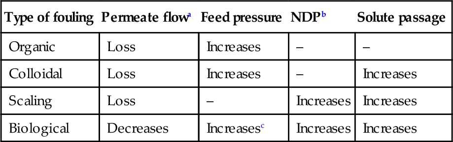
a Normalised permeate flow.
b Net differential pressure across the membrane array.
c Due to restrictions in the fouled feed channel Vexar spacer of SW membrane elements.
Measures to prevent or control fouling and scaling include using solution-compatible membranes, i.e. hydrophilic or hydrophobic membranes; using low fouling membranes, e.g. charge compatible membranes; reducing product water recovery; and optimising pre-treatment strategies such as anti-scalants, acidification, water softening and fine filtration and prefiltration in the case of RO and NF systems [32,33]. Several novel techniques for controlling fouling and enhancing flux are given in Table 1.13.
Process parameters – temperature, flow/shear, pressure, feed pH and concentration – influence fouling, for example, the solubility of salts is a function of temperature. Similarly, since protein molecules denature at high temperatures, fouling of UF membranes increases with temperature (30–60°C) due to greater adsorption [34]. Proteins are least soluble at pH 4–5 resulting in maximum fouling in this range. General rules of thumb for preventing or minimising fouling and scaling in RO/NF membrane systems are turbidity less than 1.0 NTU, SDI less than 3.0 and LSI less than zero.
Critical flux operation. Critical flux is defined as the limiting flux below which a flux decline over time does not occur, as discussed in Chapter 1. The pure water flux in pressure-driven processes is directly proportional to the applied hydraulic pressure shown in Figure 1.8. The curves also show that for feed solutions containing solutes, as ΔP increases the flux reaches a plateau (Region III) and becomes independent of pressure [34,35]. This steady-state flux is called the “limiting flux,” Jlm or gel layer limited flux. In order to reduce the formation of the gel layer and fouling, membrane systems should be operated in the so-called “critical flux” region, Region II in Figure 1.8. The critical flux increases with higher cross-flow velocity (higher Reynolds number) and lower solute concentration, Cb. The limiting flux behaviour for various feed waters in RO membrane modules is illustrated in Figure 2.27.
Hydrodynamic fouling control. Advanced membrane processes such as the vibratory shear-enhanced process (VSEP®) have proven to be very effective in reducing fouling and treating difficult waters such as produced waters [36]. The technology uses vibrational energy that creates shear waves at the membrane surface, repelling solids and foulants, as discussed in Chapter 1. The VSEP membrane module uses RO, NF, UF or MF membranes depending on the application.
Hydrodynamic methods applying backwash are a part of the operating cycle of cross-flow and dead-end UF and MF systems [34]; during backwash the filtered water flows in the reverse direction, as shown in Figure 2.5, to dislodge the solids and restore the flux lost as a result of cake build-up on the membrane surface and clogging of the membrane pores. The membrane modules are either tubular (cross-flow only) or hollow fibre. In the case of low-pressure membrane filtration systems operating in semicontinuous dead-end mode the backwash is often combined with air scour either during filtration and/or backwash cycles [6,9]. Air-scouring helps to shear off the layer somewhat acting like tangential velocity in cross-flow systems. Backwashing the membrane elements by air scouring and air-assisted backwashing is done intermittently every 30–60 min. The backwash cycle typically lasts 1–2 min, as discussed in Chapter 4.
Start-up conditions. In the case of high flux UF and MF membranes, it has been shown that if the system is started slowly, fouling is reduced; for example a slow start resulted in 10–25% higher long-term flux than abrupt start-up when processing raw sugar solutions [34]. Maintaining a high permeate back-pressure, ramping up the pump motor speed and reaching the final TMP, minutes or hours after start-up, allow operation below the critical flux for that system.
2.3.1 Scaling and fouling mechanism
Each ionic compound has its own solubility limit, which is the maximum amount of the compound that can remain in solution. This is defined as the solubility product constant, Ksp. It is a function of temperature, pressure and pH; slight variations in any of these properties can shift the solubility point and cause scaling. Ksp values of various compounds are given in Chapter 6. For this reason, membrane processes are not operated under conditions of solubility limits (unless an anti-scalant is in the feed) because in this zone – metastable region – precipitation can occur when favourable conditions exist [14,32,33].
Phase changes occur at solid (membrane)/liquid interfaces where precipitation occurs easily if there are nucleation sites. Precipitation occurs at a finite rate depending on the number of nucleation sites, the degree of saturation, temperature, pressure and time. Once the process of precipitation starts, the rate is controlled by the size of the solid/liquid interfacial area. If the particles are attached to a membrane surface, they grow in only one direction because the membrane limits access to the adjacent surface. Thus particles grow as a sheet until they form a layer of precipitate on the membrane surface, and the membrane gets fouled. The solute concentration is maximum at the membrane surface and lower in the bulk liquid above the membrane surface; the concentration profile is the reverse of a fluid flow profile in a channel or a tube, as shown in Figure 1.23.
Crystallisation and scaling initially occurs at sites with the greatest amount of available free energy. Most membrane surfaces are relatively low energy surfaces unlike the bulk solution, which has many imperfect solid surfaces such as suspended solids, which are ideal for crystal growth. In the bulk solution there are nucleation sites such as colloidal particles in the feed solution, or are formed by chemical precipitation. Fouling occurs when the number of nucleation sites at the membrane surface is large in comparison to the number of sites away from the membrane surface [36]. Hence, it makes a difference whether the nucleation sites are at the membrane surface or in the bulk solution.
2.3.2 Membrane scaling
Scaling occurs when sparingly soluble salts get concentrated beyond their solubility limits in the reject stream of the membrane element. The process of scaling occurs in multiple stages. During the scaling process, colloids of insoluble mineral salts are formed. Minerals that precipitate and form scale are predominantly divalent metal ions such as calcium, iron, magnesium, barium, strontium and silicon because they are almost insoluble in the presence of sulphate, phosphate and carbonate ions. For example, barium sulphate forms scale when the barium concentration is as low as 0.05 mg/l. As these molecules precipitate they form crystals that start growing at nucleation sites, especially at a liquid/solid interface [32,33]. Monovalent metals such as sodium and potassium, on the other hand, are almost completely soluble. Sparingly soluble salts in the order of decreasing scale formation are [14]:

The most common scale found in RO/NF systems is calcium carbonate because it precipitates quickly once concentrated beyond its solubility limit, and also because most natural waters are almost saturated with respect to calcium carbonate (magnesium, barium and strontium often co-precipitate when calcium and carbonate precipitate). Calcium carbonate chemistry and its scaling potential are discussed in detail in Chapter 6. The scaling potential is evaluated using the Langelier Saturation Index (LSI) for brackish water and the Stiff and Davis Stability Index (S&DSI) for seawater (see Table 2.6).
Table 2.6
Feed water requirements to minimise scaling
| Parameter | Value |
| LSI (TDS < 10,000 mg/l) | < 1.0 w/ antiscalant < 0 w/o antiscalant |
| SDSI (TDS > 10,000 mg/l) | < 0.5 w/ antiscalant < 0 w/o antiscalant |
| Barium | < 0.05 mg/l |
| Strontium | < 0.1 mg/l |
| Silica, reactive | 60–150 mg/l |
In the case of brackish waters, CaCO3 and gypsum (CaSO4 · 2H2O) are the most common scalants. Gypsum is ~ 50 times more soluble than calcium carbonate based on their Ksp values (gypsum, Ksp = 1.9 × 10− 4 at 25°C; calcium carbonate, Ksp = 8.7 × 10− 9 at 25°C).
Calcium carbonate, carbon dioxide, calcium and bicarbonate ions are in equilibrium:
According to Equation (2.29) calcium carbonate precipitation is favoured by increasing calcium or bicarbonate concentration, decreasing carbon dioxide and increasing temperature or pH. Carbonate – CaCO3, SrCO3, BaCO3 – scaling is prevented by lowering the pH, adding a scale inhibitor, softening (discussed earlier), reducing product water recovery, preventive cleaning, or a combination of all these techniques [14,33]. Scaling compounds such as hydroxides of aluminium, iron and manganese are typically removed during basic pre-treatment.
Process and feed water requirements for minimising mineral scaling in membrane systems are given in Table 2.6. LSI quantifies the scaling potential of CaCO3. The most susceptible elements of an RO/NF system to scaling are the last stages of the membrane array where the reject stream is most concentrated (see Table 2.9). Why does the RO concentrate or reject water come into play? This is discussed below but simply, as the water in the feed/reject stream gets concentrated with the removal of the permeate, sparingly soluble salts can reach their solubility limits and precipitate to form a scale on the membrane surface. Concentration factor, CF, is defined as:
where recovery is (permeate flow rate)/(feed flow rate). In other words, when the product water recovery is 75%, the CF is 4, and the salts get concentrated by a factor of 4. A more reliable indicator of scaling used by membrane manufacturers is called the beta factor, β. It quantifies the effect of concentration polarisation, CP. Thus,
where CFM is the modified concentration factor. CP depends on the turbulence of the bulk stream in the feed channel above the membrane surface, and for design purposes β value is in the range of 1.13–1.2 for RO/NF membranes, meaning that the concentration of solutes at the membrane surface is 13–20% higher than in the bulk reject stream. In short, the actual salt concentration at the membrane surface must be accounted for when designing a RO/NF membrane system.
Feed water treatment, therefore, often includes anti-scalant addition and pH adjustment with acid to 6.5–6.8 to maintain the LSI < 1.8. Membrane manufacturer’s recommendations for salts saturation limits with anti-scalants are as follows: BaSO4 = 6000%, SrSO4 = 800% and CaSO4 = 230%. Silica solubility can be up to 300 ppm in the presence of a dendrimer anti-scalant supplied by Professional Water Technologies, Vista, California.
2.3.3 Membrane fouling
One of the most important issues affecting the development of membrane filtration has been fouling. Membrane foulants can be both inorganic and organic components. The main reasons for membrane fouling listed in Table 2.4 are:
• Organic molecules adsorption (organic fouling, e.g. proteins, humic substances)
• Particulate deposition (colloidal fouling, e.g. clay, iron and alumina silicate)
• Microbial adhesion (biofouling, e.g. bacteria)
Thus, fouling depends on membrane properties and specific interactions between the membrane and solutes in the feed as discussed in Chapter 1 [18,32,34]. Several mechanisms of colloidal and organic fouling are explicitly illustrated in Figure 2.15.
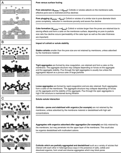
In the case of traditional UF and MF operations (i.e. non-aqueous treatment applications), the problems can be addressed by using or modifying membranes that are compatible with the liquid being processed; for example, positively charged UF membranes are used for recovering anodic paint in electrocoating, whereas negatively charged membranes are used for recovering cathodic paint; otherwise, fouling is severe as shown in Figure 2.16. Backpulsing is used with tubular hollow-fibre UF and MF membranes to control fouling as discussed earlier in this chapter. Pre-treating the feed stream is also an option; for example, in the case of milk processing by UF using polysulphone membranes, fouling occurs due to colloidal calcium phosphate, which is associated with casein micelle [34]. Addition of EDTA or sodium citrate reduced fouling due to a reduction in the calcium–caseinate complex.
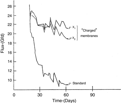
In the case of membrane filtration applications in water treatment, there is a rapid and often irreversible loss of flux due to interactions between the membrane and the components of natural raw water. The most important foulant is small colloidal matter (3–20 nm in diameter). Materials in the colloidal size range such as proteins and macromolecules are known to be the worst foulants. In addition, most of the foulants have a narrow size distribution when dealing with natural surface waters. Scaling by inorganic deposits also results in fouling because different types of fouling often occur simultaneously and influence each other.
General guidelines to minimise fouling are given in Table 2.7. As the SDI value increases, the potential for fouling increases. Most manufacturers require that the feed water SDI15 (the SDI determined by a 15-min test is described in Chapter 6) be less than five, while some require an SDI15 less than four. Turbidity specifications must also be satisfied to meet warranty conditions. Note that SDI and turbidity are only directly related. For example, water with low turbidity (less than 0.2 NTU) can still exhibit a SDI greater than five.
Table 2.7
Feed water requirements to minimise fouling
| Parameter | Value |
| SDI15 | < 5 (some manufacturers require < 4) |
| Turbidity | < 1a NTU |
| Ironb | < 0.05 mg/l |
| Manganese | < 0.5 mg/l |
| Hydrogen sulphide | < 0.1 mg/l |
| Organics (TOC) | < 10 mg/l |
a Some membrane manufacturers recommend that turbidity be < 0.2 NTU.
b At pH > 7.0 and 5–10 mg/l dissolved oxygen; at lower pH and lower oxygen levels, slightly higher iron levels can be tolerated.
Iron and manganese are included as suspended solids since under most operating conditions, iron and manganese that are soluble in RO feed water oxidise (soluble ferrous iron, Fe2 + = > insoluble ferric iron, Fe3 +) and deposit on the surface of the membranes [14]. Furthermore, oxidation of the metal can catalyse the oxidation of the membrane leading to membrane failure. The levels of iron, manganese and nickel in feed water must be less than 0.1 mg/l.
Hydrogen sulphide is considered as a suspended solid because it is readily oxidised to form colloidal sulphur; it reacts instantaneously with chlorine to precipitate sulphur at the pH of typical feed water sources. Hydrogen sulphide is found almost exclusively in well water make-up sources. Reaction with dissolved oxygen in water precipitates sulphur almost as rapidly as exposure to chlorine. Colloidal sulphur is difficult to remove from the membrane surface.
Various techniques can be used to reduce the loading of suspended solids, organics and microbes in feed water. These include physical processes such as media filtration, cartridge microfiltration and chemical treatments. Chemical addition enhances the filterability of the solids such as the addition of coagulants (Table 2.2). Foulants and their control strategies are addressed in Table 2.8. Since any traces of solids and organics get removed in the first membrane modules in RO and NF systems, these materials typically foul the first stages of an RO/NF system (Table 2.9). Once deposited on the membranes, foulants attract additional solids, thereby accelerating any fouling problem that might already exist. In addition to solids, microbes, and organics, soluble heavy metals (such as iron) can foul RO membranes when oxidised within the membrane modules. Oxidation can occur in any stage of an RO system when the pH and dissolved oxygen concentration are suitable. Microbes, if left untreated, can reproduce and spread, thereby fouling the entire RO system.
Table 2.8
Treatment methods for controlling fouling
| Foulant | Fouling control |
| General | Hydrodynamics/shear, operation below critical flux, chemical cleaning |
| Inorganic (scaling) | Operate below solubility limit, pre-treatment, reduce pH to 4–6 (acid addition), low recovery, additives (anti-scalants) Some metals can be oxidised with oxygen |
| Organics | Pre-treatment using biological processes, activated carbon, ion exchange (e.g. MIEX), ozone, enhanced coagulation |
| Colloids (< 0.5 μm) | Pre-treatment using coagulation and filtration, MF, UF |
| Biological solids | Pre-treatment using disinfection (e.g. chlorination/dechlorination), filtration, coagulation, MF, UF |
Source: [32].
Table 2.9
Fouling/scaling location
| Type of foulant | Most susceptible locationa |
| Scaling/silica | Last element of last stage |
| Metal oxides | First element of first stage |
| Colloids | First element of first stage |
| Organic | First element of first stage |
| Biofouling (rapid) | First element of first stage |
| Biofouling (slow) | Throughout the whole installation |
Source: [32].
a RO/NF membrane array.
Organic fouling
Humic acid and fulvic acid represent up to 80% of the TOC – dissolved organics – of natural waters. Humic substances are weak acidic electrolytes with carboxylic- and phenolic-OH groups with a micelle-like structure and with a molecular weight between 500 (fulvic) and 100,000 (humic). The chemical structure of humic acid is shown in Figure 6.1 [15]. They become hydrophobic as pH decreases, and thus foul hydrophobic membranes more [18]. Humic fouling in the case of natural waters is aggravated by the presence of calcium (Ca+) by forming a bridge between the membrane and the negatively charged membrane surface, and/or between negatively charged carboxyl groups of the humic acid. Other organic components that foul membranes include microbial slime, polyhydroxy aromatics and polysaccharides. Feed water organic levels measured as TOC should be low to prevent fouling with organic molecules as well as to minimise the potential for microbial fouling since organics provide nutrients that support microbial growth.
Colloidal fouling
Most common colloids found in natural waters are clays, silica, iron and aluminium hydroxides, and organic debris. In the case of industrial process streams, colloids may be paint pigments, proteins, bacterial and yeast cells, and high molecular weight alcohols. Colloidal fouling in a membrane system is caused by the convective deposition of colloids on the membrane surface, and the higher the permeate flux, the higher the rate of colloidal fouling. Membrane systems and operating conditions are designed to reduce the risk of colloidal fouling since it is the most severe [31,32]. These control measures include feed water pre-filtration, reduced recovery, higher cross-flow velocity and frequent chemical cleanings.
Silica fouling
Silica is one of the most common elements, and is present in many natural waters. It is found in waters in the form of (a) reactive silica, (b) colloidal silica, and (c) suspended particles (sand). Reactive silica is called silicon dioxide, and in this form is generally not ionised at normal pH levels of water [33,37]. Colloidal silica is either polymerised silicon with multiple units of silicon dioxide, or silicon that has formed loose bonds with organic compounds or other complex inorganic compounds such as calcium oxide and aluminium silicate. Well waters contain the most silica, from 50 to 100 mg/l. It is mostly reactive silica, a result of dissolving from rock, whereas surface waters contain more colloidal silica even though surface waters contain more reactive silica than colloidal silica. In the case of surface waters, silica chemistry is complex due to biological activity.
Silica has a low solubility of 120 mg/l at pH of 7.0 and 25°C, and silica scale-like barium sulphate scale is difficult to dissolve during cleaning and must be avoided. Silica scaling usually occurs in the last stage of a membrane array (Table 2.9). It is usually associated with iron and alumina (e.g. clays, mullite and feldspars); metal hydroxides adsorb silica to form silica–metal complexes such as aluminium silicates that readily foul the membranes. Iron fouling can be prevented by (a) anti-foulants, or (b) removing iron by oxidation as by greensand filtration or iron filters. Alumina fouling is prevented by (a) pH control and coagulation prior to multimedia filtration, or (b) alumina compatible anti-scalants. If silicates are less than 5 ppm, iron should be less than 0.5 ppm and manganese less than 0.2 ppm, and when the silicates are 30–50 ppm, iron should be less than 0.05 ppm and manganese less than 0.02 ppm. In addition, hardness should be removed and alumina should be less than 0.05 ppm. A dispersant such as high molecular weight polyacrylate scale inhibitor is helpful in silica scale control by slowing agglomeration of silica-scale particles.
The solubility of silica is a function of pH and temperature. Lime softening and lime plus soda ash softening are most effective in removing silica. Other options are process related: (a) run the RO system at reduced recovery, (b) increase the feed water temperature – silica solubility increases with temperature, and (c) use silica inhibitors. Colloidal silica is difficult to remove by IX because it is not ionised, and can foul the resins when the levels are high. Colloidal silica flocculates easily in boundary layers resulting in severe fouling. It can be removed by UF membranes with a MWCO of up to 100,000 Da. Since the solubility of the silica increases below a pH of about 6.0 and above a pH of about 9.0, the actual solubility of silica in the concentrate stream is further affected by the pH of reject water.
Biofouling
Biological fouling by microorganisms has an adverse effect on membrane performance (Table 2.5). A biofilm is difficult to remove because it protects the microorganisms from shear forces and disinfection chemicals. Microorganisms – bacteria, algae, fungi, viruses, and higher organisms – can be regarded as colloidal matter (typical bacteria size is 1–3 μm). Biofouling can be complicated due to mutual interactions between different types of fouling; for example if iron oxide or a biofilm accumulates on the membrane surface it prevents the migration of ions (calcium, sulphate) and other solutes back into the bulk solution, as discussed in Chapter 1, resulting in a supersaturated condition. Thus gypsum (calcium sulphate) scale is formed beneath the primary foulant, and is not easy to remove as compared to the iron scale or the biofilm. The potential for biological fouling is higher with surface water than well water.
Biofouling has been investigated extensively [38,39]. Key characteristics are summarised below:
• Appropriate sampling of biofilms is necessary to identify biofouling. A biofilm has the following characteristics: (a) high content of water and organic matter (70–95%), (b) high numbers of colony-forming units and cells, (c) high contents of carbohydrates and proteins, (d) high content of adenosine triphosphate (ATP), and (e) low content of inorganic matter.
• RO membranes reject bacteria absolutely. However, microorganisms can be found in the permeate due to (a) leakage through O-rings, (b) microscopic imperfections in the membrane surface, (c) microbial contamination of feed water, and (d) growth of microorganisms from contaminated piping.
• Biofilm mode of growth enables microorganisms to survive and multiply even in extremely low nutrient habitats (5–100 ppb TOC).
• Generally biofouling is a slow process.
• The cumulative effects of membrane biofouling are (a) increased cleaning and maintenance costs, (b) a noticeable deterioration of product water quality, and (c) significantly reduced membrane life.
• Biofouling can lead to secondary mechanical deformation (“telescoping”) of SW membrane elements.
• Biofouling of membrane surfaces is invariably accompanied by some degree of mineral deposition.
• Biofilm can be considered as a dense gel layer, and dissolved minerals tend to accumulate in this layer and increase concentration polarisation.
• Biofouling causes flow losses due to constriction of the flow channel, increase roughness of the surface, and increase drag because of their viscoelastic properties.
• The first step in biofilm formation prior to microbial adhesion is the irreversible adsorption of macromolecules, which leads to a “conditioning film” (humic substances, lipopolysaccharides, microbial products). This conditioning film alters the effect of the membrane; the electrostatic charge and the critical surface tension may change.
• Primary adhesion is a function of several factors: (a) microorganisms, (b) membrane surface property – charge and hydrophobic/hydrophilic, (c) fluid properties, and (d) bacteria growth phase. Many bacteria have a slight negatively charge, and have to overcome the repulsion barrier when they attach to slightly negatively charged membrane surfaces. Cell hydrophobic property, however, does not seem to be crucial in adhesion to polysulphone (PS) hydrophobic membrane.
• Primary adhesion occurs within a very short time; the highest rate is during the first 1 h followed by a slow plateau after 4–6 h. Dead cells adhere as fast as living cells. This means that destruction of bacteria is not enough, and dead cells must be removed.
• Higher cross-flow velocity provides higher shear forces, and thus, a thinner biofilm. However, the shear forces of the turbulent flow do not “penetrate” the viscous sub-layer and affect the bacterial monolayer. Fluid velocities in SW modules have very little effect on impeding the initial rate of microbial (or colloidal) foulant deposition, although they can reduce the thickness of the fouling layer.
• Surface roughness has a significant effect on biofouling as it: (a) increases the convective transport near the surface, (b) protects small particles from surface shear, and (c) increases the surface area of attachment.
• Polycations from pre-treatment enhance biofouling because of the electrostatic attraction to the slightly negative overall charge of microbial cells.
• A common cause of biofouling is the overdosing of flocculants (used in removing suspended solids during pre-treatment), which provide a suitable habitat for microbial growth.
• Chlorination of seawater has been observed to induce biofouling by degrading humic acid into biologically assimilable material, which supports the growth of a biofilm.
There are several risk factors that are also applicable to non-biofouling membrane operating conditions. These should be kept in mind when operating any membrane system:
• Feed-water characteristics – Temperature > 25°C, high amounts of organic and inorganic nutrients, large number of cells (> 104 colony-forming units per ml), and high SDI.
• Operational characteristics – Infrequent monitoring of performance characteristics, use of microbial contaminated pre-treatment chemicals, lower cross-flow velocities, and long storage periods.
• System design – Extended piping runs, dead-legs and disinfected holding tanks.
In most cases, biofouling is assessed based on performance characteristics: (a) flux decline, (b) decrease in salt rejection, or (c) increase in feed-brine pressure drop as given in Table 2.5. These indirect methods, however, are not absolute indicators of biofouling, and cannot be used for any correlation. Common techniques and limitations for controlling biofouling include:
• Removal of the biofilm is essential for effective sanitisation because a biologically deactivated biofilm can cause biofouling.
• Chlorine is a biocide. However, it does not sterilise water, and after chlorination the surviving bacteria can grow especially between 25 and 35°C. Water has to be dechlorinated when using polyamide (PA) membranes.
• Activated carbon used for removing organics is often the source for colonising microorganisms.
• Cartridge filtration using 5.0 μm pore size cartridges are too large for removing bacteria.
• 254 nm UV irradiation is used for disinfecting water. Many types of bacteria are, however, resistant to UV light. Once a biofilm is formed UV light is not able to deactivate or remove the cells. UV treatment is limited to relatively clean water because of interference by suspended solids in water.
• Regular ozone treatment is effective for sterility, and is used in high-purity water systems.
• Hydrogen peroxide requires long contact times (a few hours), high concentrations (> 3%), or high temperatures (> 40°C). It is an oxidant and, therefore, not compatible with PA membranes.
• Detergents are effective in inhibiting biofouling in many cases. Alkaline cleaners are quite effective in controlling microbial slime. Biz® bleach is an effective cleaner but is an oxidant.
• Sodium bisulphite is effective in controlling biofouling and colloidal fouling. Typically, 500–1000 mg/l is dosed for 30 min every 24 h to control aerobic bacteria. The permeate contains 1–4% bisulphite during this shock treatment.
• Hot water sanitisation (HWS) is an effective control strategy.
• Preventive sanitisation is much more effective than corrective disinfection because a single attached bacteria is easier to kill and remove than a biofilm. Membrane life is shortened by extensive sanitisation.
2.3.4 In-line chemical treatment
The pre-treatment unit operations discussed in Section 2.2 are the basic essentials for providing acceptable water to RO/NF membrane plants. Additional treatment may be required to further minimise the potential for fouling and scaling to ensure that the RO/NF membrane plants operate from 3 to 6 months without shutdowns for cleaning, unlike MF and UF plants that are usually subject to frequent backwashing and monthly cleaning. For example, synthetic anti-foulants such as Hypersperse™ are used to prevent carbonate and sulphate scaling and to reduce the rate of colloidal fouling [31]. Dosage concentrations of various chemical additives are given in Table 6.7.
In-line coagulation
Polymeric coagulants are sometimes added in low dosages (< 10 ppm) to remove particles down to 0.5 μm particle size as compared to 10 μm without the coagulant upstream of a cartridge filter. Even very low amounts of cationic polymeric coagulants in RO/NF feed water can, however, foul negatively charged membranes. In addition, some organic coagulants are not compatible with acrylic-based anti-scalants used in RO/NF systems. Typical coagulant dosage ranges from 0.5 to 20 ppm. Inorganic coagulants generally require a higher dose than polymeric coagulants. The best technique for determining the proper dosage of coagulant is to feed the product in-line and measure the SDI in the filter effluent as a function of coagulation feed rate.
In-line dechlorination
Oxidising agents such as chlorine damage PA membranes by breaking down the polymer backbone as discussed in Chapter 6. The maximum allowable chlorine limit for PA membranes varies between 0 and 1000 ppm h. It is, therefore, mandatory that RO feed water is dechlorinated when using PA membranes. A reducing agent such as sodium metabisulphite (Na2S2O5) is used to scavenge any traces of chlorine in carbon filter effluent water. Sodium bisulphite (NaHSO3) is formed when sodium metabisulphite is dissolved in water. NaHSO3 then reduces hypochlorous acid as per the reaction:
In theory, 1.34 mg of sodium metabisulphite (100%) is required to remove 1.0 mg of free chlorine. In practice, 3.0 mg is used. Similarly, it takes 1.46 ppm of sodium bisulphite and 1.77 ppm of sodium sulphite (Na2SO3) to remove 1 ppm of free chlorine. A minimum contact time of 5 s is required. Sodium metabisulphite also helps in reducing dissolved oxygen in water.
In-line pH adjustment
Membrane scaling is linked to system recovery and cross-flow velocity; generally speaking, for recovery up to 70%, and with or no iron present, acidification may be the only chemical pre-treatment necessary to prevent scaling by calcium carbonate. When water recovery is 75–80%, additional processes such as scale inhibitors and/or IX softening instead of acidification is required. The solubility of calcium carbonate depends on the pH of feed water. The equilibrium can be shifted to the right to convert calcium carbonate to soluble calcium bicarbonate [Ca(HCO3)2] by lowering the pH to 6.0 with sulphuric acid or hydrochloric acid as:
Acid reacts with bicarbonate alkalinity to produce carbon dioxide. RO permeate is often high in anions and always acidic (pH < 7.0) due to the presence of dissolved carbon dioxide (carbonic acid). Carbon dioxide concentration can be several hundred ppm when using acidified feed [37]. Dissolved carbon dioxide is removed by tower decarbonation or by membrane degasification to reduce the loading on anion resins when EDI or mixed-bed IX is used for producing DI water. Membrane degasification is preferred in high-purity water systems to prevent contamination. Alternately, IX softening is used to remove calcium ions followed by raising the pH of the softened water to 8.3–8.5 by adding caustic soda. Raising the pH with sodium hydroxide converts the carbon dioxide to sodium bicarbonate, which is easily rejected by RO membrane.
Acid addition is determined by the LSI or SDSI of RO reject water. To control calcium carbonate scaling by acid addition alone, the LSI or SDSI in the concentrate stream must be negative as indicated in Table 2.6. When an anti-scalant (A/S) is used, the LSI can be 1.0. LSI is applicable when the TDS is less than 10,000 mg/l, whereas SDI is applied when the TDS is greater than 10,000 mg/l.
Sulphuric acid is commonly used but hydrochloric acid is preferred when the scaling potential is high due to CaSO4, SrSO4, and BaSO4. Calcium sulphate is more soluble than BaSO4 and SrSO4. However, since calcium ion is present in natural water sources more abundantly than barium and strontium ions, CaSO4 is a greater problem. Nevertheless, BaSO4 and SrSO4 scale is difficult to re-dissolve once precipitated. Hence, overdosing of sulphuric acid must be avoided. Acidification, however, has several limitations:
• Low pH increases fouling by natural organic matter (NOM) such as humic acids.
• Low pH lowers permeate quality due to higher TDS of feed water and increase in silica and carbonic acid.
• Permeate TDS increases when using hydrochloric acid because added chloride has a lower rejection than sulphate. Hence, acid treatment is usually used for carbonates and phosphates scale prevention.
Anti-scalant threshold treatment
Scale inhibitors or anti-scalants (A/S) are generally organic compounds containing sulphonate, phosphonate, or carboxylic acid functional groups and chelating agents such as carbon, alum and zeolites that sequester and neutralise a particular ion that may be formed. The majority of scale inhibitors can be classified as “threshold inhibitors.” In addition, chelating agents such as EDTA (tetra sodium salt of ethylene diamine tetra acetic acid) are used to control hardness (at pH > 6.0) and metallic ion deposits. Anti-scalants prevent mineral scaling by getting absorbed on the scale forming salt crystals thereby preventing the attraction of the supersaturated salt to the crystal surfaces. Since anti-scalants inhibit the growth of crystal, it does not grow to a size or a concentration large enough to precipitate out of the suspension. Many scale inhibitors also contain dispersants that keep the precipitates suspended in solution [14,40,41].
Anti-scalants are preferred to IX softening when the feed water hardness is less than 100 ppm because of cost and ease of operation. Although anti-scalants are very effective in preventing carbonate and sulphate scaling of membranes, they do not prevent scaling from occurring; rather they delay the formation of large crystals that form scales. The effectiveness of scale inhibition is approximately 30 min. A RO/NF system that uses anti-scalants must be designed with automatic flush cycle after shut down to prevent scaling by concentrated salts in the feed-reject channel above the membrane surface.
Anti-scalants can be used alone, but are almost always used with acid feeds. When acid is used with an A/S, the LSI value (of the reject stream) of 1.0 is acceptable (see Table 2.6), although some A/S manufacturers claim an LSI of 2.7 is acceptable when using their recommended product [42]. The A/S dosage ranges between 2 and 10 ppm depending on the scale-forming potential of the RO feed water, product water recovery and manufacturer’s recommendations. The main advantage of a higher LSI value is that the RO/NF system can be operated at higher recovery resulting in lower operating costs. From a process point of view, higher recovery results in higher salt concentration in the feed-reject channel that in turn results in sparingly soluble salts exceeding their solubility limits faster. Hence, high recovery is only an option when operating a second-pass RO unit or when the feed water is pure.
Although the solubility of silica is ~ 120 mg/l at neutral pH and 25°C, the solubility increases with temperature and at pH > 9.0 (also at pH < 6.0). For normal operation, silica solubility can be increased to 300 mg/l in the presence of a dendrimer A/S [42]. Dendrimers are highly branched polymers. Dendrimer-based anti-scalants do not contain phosphates and do not foul membranes even when the A/S concentration exceeds 100 ppm. Also, the membrane manufacturer’s recommendation the following saturation limits for other sparingly soluble salts when anti-scalants are used: BaSO4 = 6000%, SrSO4 = 800% and CaSO4 = 230%.
Sodiumhexametaphosphate (SHMP) is a threshold agent derived from the dehydration of orthophosphoric acid or its sodium salt. It is used to inhibit the formation of calcium carbonate and metallic sulphate scale. It is mostly widely used because it offers good inhibition at a low cost. Depending on the concentration of calcium and sulphate, and depending on the CF (Equation 2.31), the dosage is in the range of 2–5 ppm. SHMP can prevent calcium sulphate precipitation up to 150% of the saturation limit. Organophosphonates are an improvement over SHMP since they are more resistant to hydrolysis, but are more expensive. They offer scale inhibition and dispersion ability similar to SHMP [14,40,41].
Polyacrylic acids (PAA) are good at both scale inhibition and dispersion, and are more effective than SHMP. Polyacrylic acids with high molecular weight distribution show the best dispersion ability at the cost of scale inhibition ability. However, precipitation may occur with cationic polyelectrolytes or multivalent cations such as aluminium or iron, resulting in fouling the membranes. Blend inhibitors are a combination of low (2000–5000 Da) and high molecular weight (6000–25,000 Da) of PAA or a blend of low molecular weight PAA and organophosphonates, giving excellent dispersive and inhibitor performance.
Anti-scalant treatment can, however, contribute to fouling largely due to either under-dosing or over-dosing; the former can result in scaling while the latter can lead to fouling [37,41]. Overdosing can also lead to biofouling and can result in complexes formed with hardness ions (since assimilable organic carbon content is a food source for microorganisms).
2.4 Membrane Systems Design
The design of an integrated or hybrid membrane water system entails a comprehensive design of the feed water treatment system, the design of the membrane array based on optimum product water recovery and solute rejection, membrane feed water pressure, process control and post-treatment for higher purity product. Membrane system design, therefore, is an iterative procedure encompassing membrane selection (size of membrane element and type of membrane), membrane array (number of stages and passes, and number of elements), design, and product quality calculations until the desired quality is obtained. In the case of RO and NF systems, membrane manufacturers have generated computer programmes for designing their membrane-based systems. In the case of UF and MF systems, however, pilot data are required to design a membrane system.
2.4.1 RO/NF system basics
The RO and NF membrane processes are discussed in detail in Chapter 1. RO membranes are well-suited to rejecting dissolved ions and most organics (some organics such as ethanol and acetone have very low rejections of 45–55%). The rate of water transport through a membrane depends on membrane properties (polymeric, chemical, morphological), water temperature, and the difference in applied pressure across the membrane, less the difference in osmotic pressure between the concentrated and dilute solutions. Osmotic pressure is proportional to the solution concentration and temperature, and depends on the type of ionic species present. For solutions of predominantly sodium chloride at 25°C, a rule of thumb is that the osmotic pressure is 0.7 bar per 1000 mg/l concentration (see Table 6.11 for osmotic pressures of various solutions).
The choice of a membrane is usually determined by the composition of feed water and the final product water quality. Homogenous asymmetric cellulose acetate (CA) membranes (blends of CA and cellulose triacetate) and thin-film composite (TFC) membranes are the most commonly used, as discussed in Chapter 1. Performance specifications of CA and PA membranes are detailed in Table 1.6. CA membranes have a neutral charge, are more hydrophilic, less prone to fouling, and can tolerate low levels of chlorine. Because of these properties, CA membranes are often preferred in wastewater applications where the SDI is high, and in potable water purification where residual chlorine is required. TFC polyamide and polyetherurea (PEU) membranes have higher rejection and flux and higher durability than CA membranes but are have very limited tolerance to chlorine. TFC membranes have a higher rejection than CA membranes due to co-ion repulsion since the membrane has a net negative charge at a pH greater than 5.0. Below a pH of 4.0, the membrane has a net positive charge. Hence, at low pH values (e.g. due to the presence of carbon dioxide/carbonic acid), the rejection decreases. In order to increase the dissolved ion rejection, caustic soda is often injected (unless the feed water is degasified) to raise the pH to between 7.0 and 8.0. Under alkaline conditions, the CO2 is converted to bicarbonate and carbonate ions by raising the pH to greater than 7.5. The sodium bicarbonate ions are easily rejected by the RO membrane, whereas carbon dioxide is not. Several applications of TFC membranes are listed in Table 1.8.
Membrane manufacturers are continuing to develop newer and more efficient membranes and modules such as (a) high rejection, (b) high flux, (c) loose-wrap, (d) hot water sanitisable (80°C), (e) low energy, (f) low fouling, and (g) hydrophilic. SW modules are compact and inexpensive. The flow regime in SW elements is turbulent with superficial velocities ranging between 10 and 60 cm/s corresponding to Reynolds (Re) numbers of 100–1300. Although these Re numbers indicate laminar flow, turbulence is due to the mesh spacers in the feed channel shown in Figure 2.17.
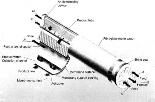
Standard SW modules are 20 cm diameter × 100 cm long with a membrane surface area of 41 m2 (see Table 2.10). Larger SW modules (40 × 100 cm and 45 × 150 cm) have been developed for seawater and brackish water desalination. These larger modules are more efficient and result in lower system costs. The surface area of 40 cm diameter × 104 cm long (nominal) modules is 158 m2. The world’s largest SWRO desalination plant (540,000 m3/day) in Sorek, Israel (commissioned in 2013) is the first large desalination plant using 40 cm diameter SW modules.
Table 2.10
Typical specifications of RO and NF membrane spiral wound elementsa
| Item/property | NFb | BWROc | BWROc | SWROd |
| Membrane type | Thin-film composite polyamide | Thin-film composite polyamide | Homogenouse, cellulose acetate blends | Thin-film composite polyamide |
| Salt rejection | ~ 99.7% MgSO4, > 50% NaCl | 99.7% | ~ 98% | 99.8% 92% boron |
| pH operating range | 3–9 | 2–11 | 4–6 | 2–11 |
| Feed pressure (max) | 40 bar g | 40 bar g | 15–30 bar g | 82 bar g |
| Pressure drop (max) | 0.7 bar | 0.7 bar | 1.0 bar | 0.7 bar |
| Max. temperature | 45°C | 45°C | 40°C | 45°C |
| Chlorine (oxidants) tolerance | < 0.1 ppm | < 0.1 ppm | 2–5 ppmf | < 0.1 ppm |
| Feed water turbidity (max) | 1.0 | 1.0 | 1.0 | 1.0 |
| Feed water SDI (max) | 5.0 | 5.0 | 5.0 | 5.0 |
| Membrane surface area | 40.8 m2 | 40.9 m2 | 49 m2 | 40.8 m2 |
| Feed flow rate | 17 m3/h | 17 m3/h | 8 m3/h | 17 m3/h |
| Product water recovery | 15–17% | 15–17% | 20% | 10–12% |
| Flux – see Section 2.4.3 | – | – | – | – |

a 20 cm diameter × 100 cm long (nominal). Note: Membrane surface area of 40 cm diameter × 100 cm long (nominal) elements is ~ 158 m2.
b Nanofiltration.
c Brackish water RO.
d Seawater RO.
e Phase inversion homogenous asymmetric.
f 2 ppm for standard CA blends, up to 5 ppm for CTA hollow fibre membranes (e.g. Toyoba SWRO).
Spiral-wound loose wrap or full-fit modules (FFM) are used in many pharmaceutical systems because there are no brine seals to prevent the by-pass of feed water. When a brine seal is utilised, a large pocket of water remains stagnant around the RO membrane. Since the water is not chlorinated in the case of PA membrane elements, stagnant water is prone to bacterial growth on the outside surface of the membrane. A FFM uses the feed pressure to expand the membrane diameter. This expansion provides the control of feed water by-pass while allowing a small flow of water to pass around the membranes outer surface. This small flow of water eliminates the stagnant pocket of water that the brine seal units retain, and can be rinsed in much shorter time. Hence the FFM offers better control of bacterial growth and is often used for pharmaceutical applications. The by-pass flow may be as high as 20% of the feed flow to the membrane. This means that the cross-flow velocity is considerably lower and the permeate flow rate is produced with less feed water when compared with membranes that utilise brine seals (because some flow is by-passed and not available for filtration). The actual recovery is, therefore, considerably higher when compared with membranes that utilise brine seals.
An RO/NF membrane unit consists of the following components: (a) a high-pressure pump, (b) a membrane element/pressure vessel assembly (array), (c) instrumentation, and (d) a clean-in-place (CIP) unit (see Figure 2.25). A typical RO/NF membrane assembly consists of either spiral-wound (SW) or hollow-fibre (HF) membrane elements housed in fibreglass-reinforced plastic (FRP) or stainless steel pressure vessels. Two to seven SW elements are connected in series in a single-pressure vessel depending on the feed flow and system design as shown in Figure 2.18. Pressure vessels can be 8–10 m long. The desired system capacity and recovery are achieved by connecting pressure vessels in parallel, and by staging the reject stream in an array with a decreasing number of pressure vessels; the tapered configuration design is shown in Figure 2.19. The brine volume gets reduced in each stage, so that the number of modules in successive stages is reduced usually in the ratio of 2:1 to maintain optimum reject-flow velocities. High feed channel flow velocity is desired in order to reduce concentration polarisation at the membrane surface. The number of elements required is calculated using the formula:
![]()
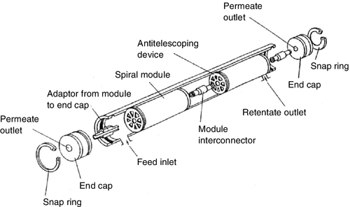

The amount of product water (permeate) recovered is generally dependent on: (a) the total area of membrane within each vessel; (b) membrane pressure supplied by the high-pressure pump(s); (c) reject-flow rate; and (d) feed water quality. General rules of thumb for RO membrane product water recovery are as follows: (a) 70–75% for normal or brackish feed water, (b) 30–45% for seawater, (c) 80–85% for purified feed water, e.g. first-pass RO permeate as second-pass RO feed and (d) 40–45% for seawater.
RO/NF systems used for brackish water and low TDS feed water are invariably two or three-stage designs as shown in Figure 2.19 (see also Figures 2.22, 2.23, 4.7). Seawater RO systems, on the other hand, are typically single-stage designs (see Figure 3.33) because of low product water recovery.
During RO/NF operation water is forced into the membrane module pressure vessel by a high-pressure pump at pressures in the range of 10–30 bar g for brackish water and from 55 to 80 bar g for seawater. The desalted product (permeate) is removed from the opposite side of the membrane at low pressure. A flow-regulating valve on the reject side is used to create back-pressure and increase recovery, as shown in Figure 2.20. The total pressure drop from the feed inlet to reject outlet is minimal (< 2 bar g), which allows the high-pressure reject to be fed to successive RO stages to increase recovery or productivity.
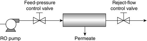
The simplest membrane element assembly consists of one pressure vessel containing one membrane element with a product water recovery (yield) of about 15%. In order to increase %recovery and still maintain an acceptable concentrate flow, a part of the concentrate stream may be recycled to the inlet side of the high-pressure pump. Concentrate recycling design is used with very small RO units and is discussed later in the chapter (e.g. see Figure 2.24). The main advantage is the compact size of the RO unit. The disadvantage is a larger feed pump to handle higher feed flow. Accordingly, the power consumption is relatively higher than that required in a multistage configuration. In addition, due to blending of the feed with the concentrate stream, the average feed salinity is increased. Therefore, both the feed pressure and the permeate salinity are higher.
For some applications, a single-pass RO system may not be capable of producing permeate of a required quality. For example: (a) seawater RO systems, which operate on a very high salinity feed water, at high recovery and/or at high feed water temperature; and (b) brackish RO systems, which require very low permeate conductivity for supplying make-up water to high-pressure boilers. Two-pass RO systems are also used in the production of high-purity water for semiconductor, beverage, medical and pharmaceutical production to optimise solute rejection and productivity. In this design, the primary (first-pass) unit permeate is fed to the secondary (second-pass) unit (e.g. see Figure 2.21). Because of very low dissolved solids ion content of the first-pass RO permeate, the second-pass RO membranes can operate at a higher flux (e.g. 34 lmh) and high recovery (e.g. 85–90%). Further, to increase the overall recovery and conserve water, the reject stream from the second pass is recycled back to the RO pump inlet. The dissolved ion concentration in the concentrate from the second-pass is usually lower than the concentration of the first-pass unit feed water. Therefore, blending the first-pass feed water with the second-pass concentrate reduces slightly the concentration of the feed and increases product water recovery.
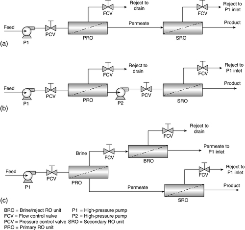
2.4.2 Membrane system controls
Of all the major membrane processes, RO/NF separation is the most complex both in terms of operation and controls [43]. RO (and NF) membrane systems operate in a continuous mode with minimum or no recycle. RO desalination plants can be generally quite large (see Table 3.5); for example the largest seawater RO desalination plant in Sorek, Israel has a capacity 150 million m3/year. Further, for hybrid membrane systems the process control becomes even more complex. RO/NF plants require different levels of process control depending upon the quality of feed water supplied and product water quality requirements.
Systems discussed provide monitoring and controls of major process variables in RO/NF plants to ensure that the design conditions of flux and rejection are achieved with minimal membrane fouling while ensuring fail-safe operation. New control systems are being designed that interlock the pressure drop across a membrane stage with the high-pressure RO pump or the membrane array inlet-pressure control valve to maintain constant permeate flux. Similarly, new systems designs are envisaged where the pressure drop is monitored across each element in a pressure vessel rather than across the entire pressure vessel or stage. Since each pressure vessel has up to seven elements in series, closer monitoring of pressure drop would help in monitoring fouling and/or scaling, and enhance system efficiency. Nowadays an increasing number of RO systems use electric motors with variable speed drives, which enable adjustment of flow and feed pressure of the pump over a wide range with very little loss in efficiency. The variable speed drive thus reduces pressure losses, and the membrane units can be operated at constant flux.
Basic controls
The basic level of control routinely used in the chemical process industries involves sequencing operations such as manipulating valves or starting/stopping pumps, instrument verification, data acquisition, on-line maintenance and fail-safe shut down procedures. The next level of computer control involves process control of parameters such as flow, pressure and temperature. RO/NF systems require both levels [43].
The simplest form of RO/NF system contrail entails the adjustment of only two variables: membrane inlet pressure and reject-flow rate, as shown in Figure 2.20. These functions affect the quantity and quality of RO permeate and indirectly potential for membrane fouling. The reject-flow control valve must be throttled in conjunction with the inlet-pressure control valve to achieve the desired productivity or product water recovery, i.e. yield.
Several more complex valve control sequences are illustrated in Figure 2.21. In a two-pass RO system (Figure 2.21a), the first-pass RO inlet-pressure and reject-flow control valves are adjusted simultaneously with the second-pass RO reject-flow control valve to achieve the desired recovery. In the case of a two-pass RO system (Figure 2.21b), where the feed to the secondary RO unit is re-pressurised, the secondary membrane unit inlet-pressure control valve is also adjusted. In order to reduce the size of the waste stream and increase overall product water recovery, the reject stream from the primary RO unit is sometimes further processed in a brine RO unit (Figure 2.21c). In such setups, the primary RO inlet-pressure and reject-flow control valves, the brine RO reject-flow control valve and the secondary RO reject-flow control valve are all adjusted simultaneously to achieve the desired recovery.
RO system performance (%recovery and %rejection) for a given membrane is a function of the operating conditions. Hence, the control system is designed to run the system at the membrane inlet pressure and recovery specified by the system manufacturer. Membrane performance, however, declines with time due to changes in the material properties of the polymer, so that control valve settings periodically require adjustments – for instance, raising the membrane inlet pressure. In addition, the control system may be used to monitor RO/NF pump inlet and outlet pressures, membrane reject and permeate pressures, membrane array pressure drop (ΔP), feed water temperature, pH, conductivity, chlorine level and permeate conductivity. Continuous monitoring of RO/NF performance, alarms, shutdown regime, data logging and performance trending are essential; for example, high ΔP across a membrane stage or an array is a good indicator of membrane fouling.
When specifying the high-pressure feed pump, membrane manufacturers assume that membrane flux will decline by about 20% in 3 years. The pump is, therefore, designed to provide feed pressure corresponding to the initial membrane performance and to compensate for expected flux decline. In the case of centrifugal pumps, the pump selected is oversized, and during operation the feed pressure is regulated by throttling (turning down the pump discharge valve) or by a variable frequency drive.
Control systems
A programmable logic controller (PLC)-based membrane system utilises remote input/output (I/O) functionality. The PLC communicates with various remote I/O control enclosures in the membrane plant, and performs all sequencing and inter-locking functions. In a fully automated system, independent (non-PLC) controllers such as PID (proportional plus integral plus derivative) or other tuning allow the operator to modulate control valves, e.g. feed water temperature, membrane inlet pressure and reject-flow rate [43]. The PID controllers also give the operator easy access for changing set point values, and supervise alarm conditions without the need for an operator interface screen. Independent PID controllers can allow the operator to run the system without a working PLC; if a single independent PID controller fails, only the particular parameter it was controlling cannot be adjusted.
Process control valves
Membrane feed-pressure control may be performed via two different techniques: proportional valve position or pump motor speed [43]. The valve solution is generally less expensive in initial capital but solid state control of pump motor speed reduces operating expense because electrical power savings can be realised over the life of the equipment. The long-term reliability of the motor speed solution is greater if done properly, but the process control is slightly better with the proportional control valve.
Control of the reject-flow rate can only be achieved with the use of a proportional valve. Since the type of valve can affect the performance of the system, the valve should be capable of reducing the pressure (up to an order of magnitude bar, if necessary) while maintaining a smooth linear response throughout the required range of flows. In seawater RO applications, energy recovery from the high-pressure reject stream (> 55 bar g psig) is an important economical requirement [44,45]. High-pressure drop control is, however, complex. Some systems may be designed with a fixed pressure drop, using an orifice plate, upstream of the reject control valve. The orifice plate lowers the amount of pressure that must be dropped across the control valve. Although this reduces the sensitivity of the valve, it enables the control-system output signal to operate over a greater range, thereby, increasing the accuracy of control.
The difficulty with controlling membrane feed-pressure and reject-flow rate simultaneously is that one affects the other. This gets more complicated with a two-pass system. If the membrane feed pressure is reduced, the reject-flow rate also will decrease if all other parameters (feed water temperature, quality and membrane condition) in the system remain constant. The danger, then, is that the whole system may oscillate if the PID controllers are not properly tuned. Tuning one controller for fast operation and the other for relatively slow operation is often the solution. Fast operation generally is best applied to the membrane feed-pressure controller because during start-up this parameter must be adjusted first. Manual control of these valves is, therefore, often preferred.
Incorporating the controller start-up output condition is also necessary to prevent the controller from drifting towards 0% or 100% – i.e. fully closed or fully open, respectively – during idle periods; otherwise, if the RO/NF pump starts when the membrane feed pressure or the reject-flow control valve is closed, a sudden spike in initial pump discharge pressure can result in equipment damage. Conversely, if the membrane feed-pressure valve is fully open during startup, the membrane elements are exposed to excessive pressure, which may cause compaction of the membranes in the leading elements.
Product quality controls
Feed water parameters that affect membrane life adversely such as high pH, free chlorine and high temperature are shown in Figure 2.22. Often, automatic on/off valves are provided to divert the feed or the permeate stream to drain when the stream quality is not in the desirable range. For example, if the feed water conductivity is much higher than the system is designed for, membrane scaling may result. A much higher-than-design permeate conductivity, on the other hand, indicates membrane scaling, membrane element integrity, or membrane damage. Hence, a low rejection alarm is often provided. Similarly, when the permeate flow rate exceeds the design point (or the reject flow is less than the design value), the potential for membrane scaling is substantially increased. A high recovery alarm is also included to alert the operator to reset the reject-flow control valve setting or shut down the unit.
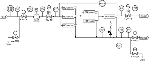
High-pressure drop across a membrane array is a strong indicator of membrane fouling due to constriction in the reject/concentrate flow channel above the membrane, and calls for membrane cleaning. Usually RO/NF plant designs incorporate an automatic 5-min flush cycle preferably with RO permeate before shutdown to protect the membranes from (a) scaling by sparingly soluble salts in the salt concentrated stagnant reject channel, and (b) biological fouling. Often the flush cycle is programmed in the PLC to run at a preset interval such as every 4 h. During flushing the high-pressure RO pump is off. Flushing minimises the likelihood of scaling and fouling but is not a substitute for feed water pre-treatment.
Safety features
RO control systems provide safety features for operating high-pressure RO feed water pumps. Pressures at pump inlet and discharge, membrane inlet, product output and reject output are, therefore, monitored by pressure switches and transmitters as shown in Figures 2.22 and 2.23. To ensure long-term safe operation of the equipment, pressure switches shut down the pump during low inlet pressure and high discharge pressure conditions. The high-pressure RO pump must be run in auto mode to ensure it shuts down automatically during an emergency. A relief valve is provided in the permeate line to protect membrane elements from damage due to any back-pressure downstream. Further, in a fully automated RO system, the membrane inlet pressure and the reject-flow control valves are of the air-to-open type. Air-to-close valves should not be used because it would result in excessive membrane pressure during start-up.
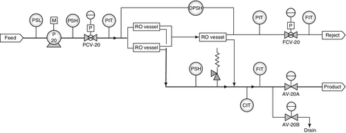
The following general process conditions are taken into consideration when designing a control system to ensure safe and reliable operation [14]:
• Product water back-pressure greater than the system pressure at any time will damage the RO membranes.
• Operate the RO unit at the lowest system pressure that produces the design flow rate and salt rejection.
• The initial minimum salt rejection is based on chloride ions and applies to each individual membrane element. The total %rejection may be lower depending on the array. Membrane deterioration may result in salt passage to double within 3 years.
2.4.3 RO/NF array design
The following basic membrane separation phenomena should be kept in mind when designing a membrane system:
• The permeate flow rate (convective) is proportional to the net driving pressure (NDP) differential across the membrane.
• The salt flow rate (diffusive) is proportional to the concentration difference across the membrane, and is independent of applied pressure.
• Permeate TDS depends on the relative mass transfer rates of water and dissolved solutes through the membranes.
• The chemical and physical nature of the membrane determines the preferential transport of water over dissolved solutes.
• The higher the permeate flux, the greater the likelihood of higher concentration polarisation (CP). As CP increases, the osmotic pressure of the solution in the feed-reject channel increases, salt passage increases, and the risk of scaling and/or fouling increases.
Membrane manufacturers provide design guidelines based on the parameters given below. These guidelines are usually modified based on the type of feed water and pre-treatment [33,40].
• Maximum feed flow rate to any element in the pressure vessel
• Maximum reject-flow rate from any element
• Maximum product water recovery for an element
• Maximum flow rate (or flux) for any element
• Maximum average flux for a system
• Maximum applied pressure
The optimal design of the RO system incorporates certain rules of thumb based on the membrane for the particular application:
• Recovery per element is < 19% for softened water or well water with SDI < 3
• Recovery per element is < 16% for unsoftened water or surface water with SDI = 3–5
• Net pressure drop across the array is < 7 bar
• Average flux for each element depending on the type of feed water1
• Percent variation in permeate flow rate is < 10% between the first and last elements in the same pressure vessel
• Feed water flow rate to the first element of each stage is the same, < 10%
In order to avoid excessive concentration polarisation at the membrane surface, permeate recovery per membrane element should not exceed 18%. In the case of brackish water RO systems, the average recovery per 100 cm (40-in.) long membrane element is usually about 9%. The overall recovery for a staged system with pressure vessels containing six elements is usually as follows [46]:
• One-stage array (1) = 52–56%
• Two-stage array (2:1) = 75–80%
• Three-stage array (4:2:1) = 85–90%
The recovery in each element is controlled by the concentration of rejected species, especially, sparingly soluble salts of calcium and magnesium and silica in the brine stream. When the product recovery is 50%, the salt concentration in the reject stream is doubled, whereas the salt concentration increases fourfold when the recovery is 75% due to the concentration factor. Hence, the RO system is operated below the design recovery point. In general, the product water recovery is maintained well below 15%, and the systems are usually designed for a recovery of 8–10% per element. The scaling and fouling potential is usually the highest in the last elements of the final stage as stated in Table 2.9.
The above conditions are taken into consideration when modelling a RO/NF membrane system. The engineers use computer-generated performance projection software provided by membrane manufacturers to design an optimal membrane array design that maximises the operating conditions and minimises fouling and scaling. A typical RO/NF programme calculates permeate quality (conductivity, pH), feed-pressure requirements, and the final concentrate stream solubility numbers such as LSI and SDSI depending on (a) permeate flow rate, (b) %recovery, (c) feed water composition, (d) feed water temperature, (e) type and number of membrane elements, (f) the rate of flux decline, and (g) the rate of salt passage increase.
The programme algorithm is an iterative calculation in which the computer first estimates a feed pressure to satisfy the desired recovery and then calculates the performance of the first element of the system [46,47]. The concentrate from the first element becomes the feed to the second element, and a second calculation of membrane element performance is made, and so on from element to element through the complete array of the proposed design. The programme then sums the permeate flow from all elements and compares this value to the target value. The programme adjusts the feed pressure based on this comparison, causing the solution to converge to the required feed pressure to achieve the required permeate recovery given the user-defined system parameters and until the programme has converged on a single unique solution. Calculations can be repeated with different design parameters or membrane element array configurations. If the programme does not converge, a warning is issued requesting a revised number entry. The programme also calculates the concentration polarisation coefficient called the β factor:
![]()
β is a function of the ratio of permeate flow from an element to the feed-brine average flow for that element. The optimum value is 1.13 for the last element of the last stage of a membrane array. To maintain this value of β when using 100 cm (40 in.) long SW elements, the maximum recovery is usually limited to 15% for one element, 30% for two elements in series, and so on to 50% for six elements in series in a pressure vessel.
Computer-generated design of a single-pass, three-stage RO membrane array (4:3:3) with concentrate recycling is shown in Figure 2.24 and given in Table 2.11. The stream numbers in the figure are 1 is raw water, 2 is blended water, 3 is membrane array feed, 4 is reject, 5 is reject/concentrate recycle, 6 is reject to drain, and 7 is permeate. The RO unit is designed to produce 27 gpm (6.13 m3/h) permeate corresponding to an overall recovery of ~ 75% (27 gpm permeate/36 gpm raw water feed). The TFC polyamide RO membranes reduce the TDS content from 421 mg/l in blended feed water to 5 mg/l in product water at an average rejection of 98.8%. A portion of reject flows to the drain at 9 gpm (2 m3/h), and the remaining recycles to the RO pump inlet at 5.5 gpm (1.25 m3/h). The design feed pressure is 145 psig (10 bar g). The β factor is within range, and the LSI is < 1, which is within range with anti-scalant dosage. The RO membranes are spiral-wound modules, 4 in. diameter × 40 in. long.
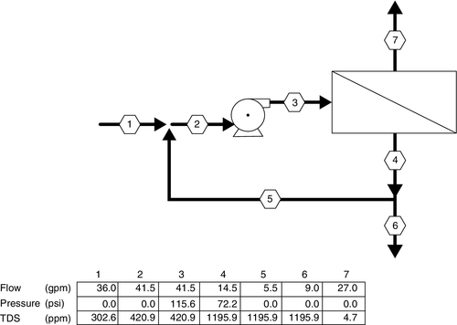
Table 2.11
RO membrane system performance projection (Hydranautics)
| Project name | Single-pass RO design | Permeate flow | 27.00 gpm | |||||||
| HP pump flow | 41.5 gpm | Raw water flow | 36.0 gpm | |||||||
| Recommended pump pressure | 144.6 psi | Total system recovery | 75.0% | |||||||
| Feed pressure | 115.6 psi | Permeate recovery ratio | 65.1% | |||||||
| Feed water temperature | 25.0°C (77 °F) | Concentrate recirculation | 5.5 gpm | |||||||
| Feed water pH | 7.14 (0.00) | Element age | 0.0 years | |||||||
| Acid dosage, ppm (100%) | 0.0 H2SO4 | Flux decline % per year | 7.0 | |||||||
| Acidified feed CO2 | 11.1 | Salt passage increase, % per year | 10.0 | |||||||
| Average flux rate | 15.2 gfd | Feed type | Well water | |||||||
| Stage | Perm. flow (gpm) | Flow/vessel | ||||||||
| Feed (gpm) | Conc (gpm) | Flux (fgd) | Beta | Conc and throt. pressure | Element type | Elem. no. | Array | |||
| (psi) | (psi) | |||||||||
| 1–1 | 12.8 | 10.4 | 7.2 | 18.1 | 1.13 | 100.5 | 0.0 | ESPA2-4040 | 12 | 4 × 3 |
| 1–2 | 7.8 | 9.6 | 6.9 | 14.8 | 1.11 | 83.8 | 0.0 | ESPA2-4040 | 9 | 3 × 3 |
| 1–2 | 6.3 | 6.9 | 4.8 | 11.9 | 1.12 | 72.2 | 0.0 | ESPA2-4040 | 9 | 3 × 3 |
| Raw water | Feed water | Permeate | Concentrate | |||||||
| Ion | mg/l | CaCO3 | mg/l | CaCO3 | mg/l | CaCO3 | mg/l | CaCO3 | ||
| Ca | 32.6 | 81.3 | 45.5 | 113.4 | 0.16 | 0.4 | 129.9 | 323.8 | ||
| Mg | 7.4 | 30.5 | 10.3 | 42.5 | 0.04 | 0.1 | 29.5 | 121.3 | ||
| Na | 47.8 | 103.9 | 66.3 | 144.2 | 1.11 | 2.4 | 187.8 | 408.3 | ||
| K | 0.0 | 0.0 | 0.0 | 0.0 | 0.00 | 0.0 | 0.0 | 0.0 | ||
| NH4 | 0.0 | 0.0 | 0.0 | 0.0 | 0.00 | 0.0 | 0.0 | 0.0 | ||
| Ba | 0.000 | 0.0 | 0.000 | 0.0 | 0.000 | 0.0 | 0.000 | 0.0 | ||
| Sr | 0.000 | 0.0 | 0.000 | 0.0 | 0.000 | 0.0 | 0.000 | 0.0 | ||
| CO3 | 0.1 | 0.2 | 0.1 | 0.2 | 0.00 | 0.0 | 0.4 | 0.7 | ||
| HCO3 | 69.3 | 56.8 | 96.5 | 79.1 | 0.80 | 0.7 | 274.7 | 225.1 | ||
| SO4 | 44.7 | 46.6 | 62.4 | 65.0 | 0.07 | 0.1 | 178.5 | 185.9 | ||
| Cl | 50.5 | 71.2 | 70.4 | 99.3 | 0.33 | 0.5 | 200.9 | 283.4 | ||
| F | 1.8 | 4.7 | 2.5 | 6.6 | 0.02 | 0.1 | 7.1 | 18.8 | ||
| NO3 | 44.7 | 36.0 | 61.6 | 49.7 | 2.11 | 1.7 | 172.4 | 139.1 | ||
| SiO2 | 3.7 | 5.2 | 0.03 | 14.7 | ||||||
| TDS | 302.6 | 420.9 | 4.7 | 1195.9 | ||||||
| pH | 7.0 | 7.1 | 5.3 | 7.6 | ||||||
| Raw water | Feed water | Concentrate | ||||||||
| CaSO4/Ksp × 100 | 1% | 1% | 6% | |||||||
| SrSO4/Ksp × 100 | 0% | 0% | 0% | |||||||
| BaSO4/Ksp × 100 | 0% | 0% | 0% | |||||||
| SiO2 saturation | 3% | 4% | 11% | |||||||
| Langelier Saturation Index | − 1.21 | − 0.79 | 0.58 | |||||||
| Stiff and Davis Saturation Index | − 1.16 | − 0.74 | 0.60 | |||||||
| Ionic strength | 0.01 | 0.01 | 0.02 | |||||||
| Osmotic pressure | 2.5 psi | 3.4 psi | 9.8 psi | |||||||
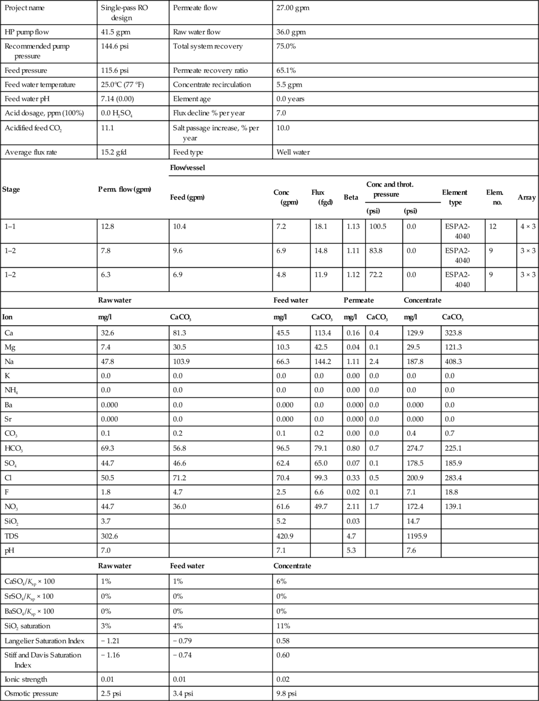
A typical RO skid is shown in Figure 2.25. It is a single-pass, two-stage (4:2 array) unit with pressure vessels containing six spiral wound membrane elements (20 cm × 100 cm) in series in each vessel. There is room on the backside of the skid to double the number of vessels to make it into an 8:4 array with permeate flow rates approaching 70 m3/h at 75%. The RO high-pressure pump is multi-stage, horizontal, submersible type. The skid includes a control panel and instruments such as conductivity and flow monitors shown on the right-hand side. The end view of a large RO/NF membrane system is shown in Figure 2.26.
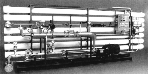

The effect of colloidal fouling on membrane processes was discussed earlier in this chapter; it is a function of the permeate flux and the solids content of the feed solution. Since colloidal fouling has a strong negative effect on membrane performance, membrane systems are designed by limiting the permeate flux of each element based on the recommendations of the membrane manufacturers. One such plot for a RO membrane with various natural water feeds is shown in Figure 2.27. The data show that as the quality of feed water improves, the recommended permeate flow rate also increases. For example, as the membrane flux is linear with pressure in the case of nearly pure water or RO permeate. The figure shows that the flux reaches a plateau at higher pressures for solutions other than pure water due to concentration polarisation (CP) as discussed in Chapter 1. The mid-point of the non-linear curve is the region of critical flux and the optimal operating condition to minimise CP as discussed earlier.