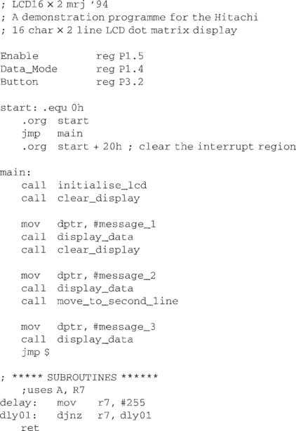
LCD Text Display Panels
Many microcontroller projects need some sort of output display unit. A simple and cheap option is based on the Hitachi 44780 IC. This drives an LCD dot matrix panel which is capable of alphanumeric and other characters. The commonly available formats are:
![]()
Depending on the type of LCD, the module (controller IC plus LCD display) will require single or dual supplies. Interfacing is very easy because of the common layout.
Table 6.1

If a backlight is fitted, it is usually supplied or controlled by additional pins 15 and 16.
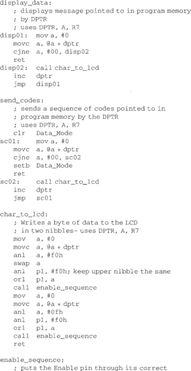
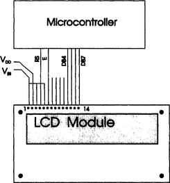
Because I/O pins are a scarce resource in most simple microcontrollers, it is a useful feature of the module that it can be driven via an 8-bit data bus (DB0–DB7) or via a 4-bit data bus (DB4–DB7). The software examples below bring the total interface down to 6 signal pins: RS, R/W, DB4, DB5, DB6 and DB7.
Most users wish to write to the module. It is not such a common need to read back what is already there. This simplifies the interface to that of Figure 6.1. The disadvantage is that the user cannot read whether the module is still busy dealing with the last character sent. In practice, this is not a problem since there is no point updating the display faster than it can be read, so simple delays (c. 100 μs) can be used between each character sent.
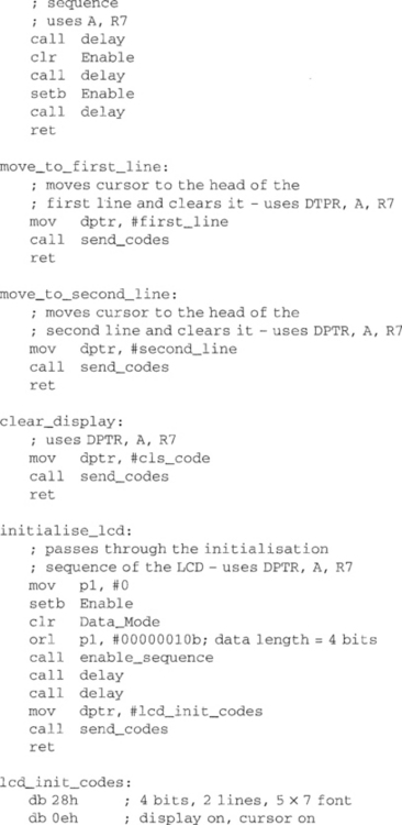
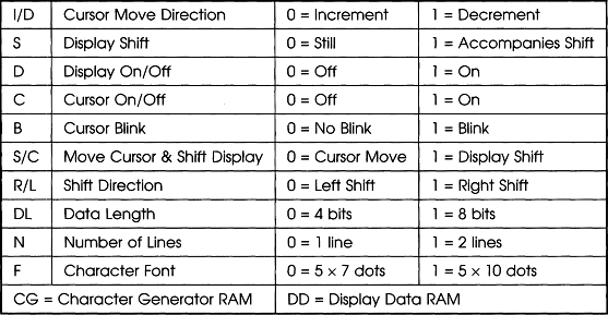
At power on, the module will reset itself. Thereafter, the microcontroller must configure the module to the correct format. Once set up for 4-bit transfer, the data and control bytes must be sent upper-nibble then lower-nibble to input pins DB4–DB7. The correct procedure is:
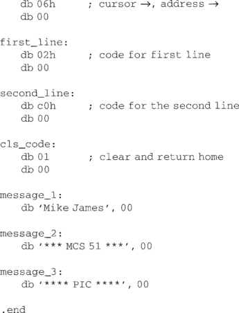
The 16 × 2 module (code on page 164) was set up with the code sequence:
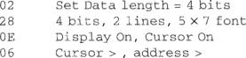
Thereafter, the data character set is essentially ASCII.
Table 6.2
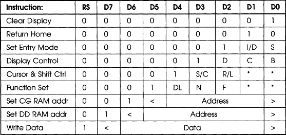
Table 6.3
In a 16 × 2, 20 × 2 or 40 × 2 display, the DD RAM address must be set at 40 to write to the second line. A 20 × 4 LCD starts each line at addresses.
Of course, the interfacing becomes even more minimal if an I2C interface is used. In many instances, this causes the cost to go up. Cost is largely a factor of units sold. At present, the parallel 4/8-bit module is the cheapest variant. If I2C is needed, it might perhaps be cheaper to have one microcontroller (83C751 or PIC16C54) interfaced to the module, itself providing an I2C interface to the rest of the world. The microcontroller would then have to mimic a slave I2C device.