
With 3G, there are equally many evolution steps. For mobile backhaul, the most important ones are:
- MSC server based core network architecture in 3GPP Rel-4
- IP transport in 3GPP Rel-5
- HSDPA in 3GPP Rel-5
- HSUPA in 3GPP Rel-6
- One tunnel in 3GPP Rel-7
- 64QAM (Quadrature Amplitude Modulation) (HSDPA), 16QAM (HSUPA) in 3GPP Rel-7
- 64QAM and MIMO (Multiple Input Multiple Output) combination (HSDPA) in 3GPP Rel-8
- Dual-cell and MIMO combination (HSDPA) in 3GPP Rel-9
- Dual-cell (HSUPA) in 3GPP Rel-9
- 4-carrier HSDPA in 3GPP Rel-10
- (Potentially) 8-carrier HSDPA in 3GPP Rel-11 (Rel-11 ongoing)
The above translates to (theoretical maximum) downlink peak rates for a single user so that with Rel-7, HSDPA 64 QAM reaches 21 Mbit/s. Rel-8, HSDPA 64 QAM with 2 × 2 MIMO achieves 42 Mbit/s. Rel-9, Dual-cell (2 × 5 MHz), MIMO and 64 QAM produces 84 Mbit/s. With a higher amount of carriers aggregated, the peak rate grows (four carriers 84 Mbit/s, and eight carriers potentially 168 Mbit/s). In practice, availability of terminals may limit the applicability. However, this illustrates that high peak rates are achievable with the enhanced HSPA+ networks.
Additionally, a number of improvements to existing functionalities have been included.
A simplified 3G system architecture with a UTRAN focus is shown in Figure 3.9.
Figure 3.9 3G system and UTRAN [37].
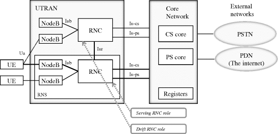
Each Node B connects to an RNC (Radio Network Controller) which interfaces the core network (CN). Iu-cs interface carries the circuit-switched traffic, and control plane (RANAP). Iu-ps carries the packet-switched traffic, and control plane (RANAP).
Node-B – RNC configuration is a static one: each NodeB is statically assigned to a specific RNC. This can be changed by a management plane configuration. No dynamic load sharing or multihoming of NodeBs to multiple RNCs exists in the standard.
RNC acts in multiple roles, for UEs and for nodeBs. For a UE, one RNC (serving RNC, SRNC) terminates the Iu link. A drift RNC (DRNC) is any other RNC than the serving RNC. For each nodeB, there is a single controlling RNC (CRNC). This controlling RNC is responsible for radio resource management of the cells of NodeBs, that are configured to that particular CRNC.
The serving RNC terminates the RANAP link to the core network, and also the RRC signalling from the UE. (Radio) L2 processing takes place in the SRNC, and the L2 protocols are carried via the DRNC to the SRNC, where they are terminated.
The NodeB is responsible for the air interface L1 processing. This includes channel coding and interleaving, spreading, scrambling, etc. With HSPA, high speed mac scheduling (i.e. part of the radio L2 protocols) move to the NodeB.
For the next two sections 3.3.1–3.3.23.2, only the IP based UTRAN interface stacks are shown. Initially all these interfaces in the UTRAN are based on ATM.
For further reading on 3G, see [37], [38], [39] and [40].
3.3.1 Circuit Switched Traffic
User plane protocol stack for the circuit switched traffic is shown in Figure 3.10.
Figure 3.10 3G circuit switched user plane (Voice example) [36], [41].

Circuit-switched traffic, e.g. voice, is over the Iub carried by FP (Frame protocol)/UDP/IP protocol stack, assuming the IP transport option. RLC (Radio Link control)/MAC (Media Access control) layer is implemented into the UE and to the RNC. At the Iu-cs interface, Iu user plane towards the circuit-switched (CS) core, RTP/UDP/IP stack is used. RTCP protocol is optional.
Iu user plane protocol (Iu UP) has two operating modes: transparent mode and a support mode for a predefined SDU size. Iu UP intends to be agnostic to the transport network layer, as well as to the core network (packet or circuit switched).
Control plane protocol stack for the CS traffic is shown in Figure 3.11.
Figure 3.11 3G CS domain control plane [36], [41].
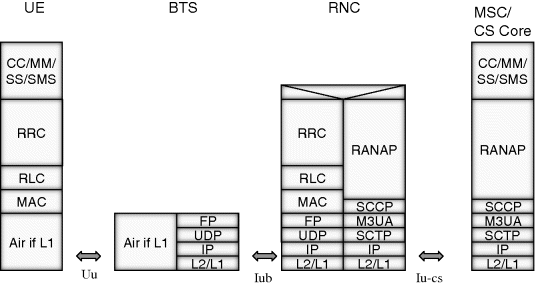
RRC messages (radio network L3 control) over the Iub are carried over FP/UDP/IP. RLC/MAC layer entities are in the UE and in the RNC. RANAP conveys non-access stratum signalling to the CS core (MSC).
In the IP protocol option of Iu, RANAP is mapped over the SIGTRAN protocol stack; SCCP/M3UA/SCTP/IP.
3.3.2 Packet Switched Traffic
Protocols for the user plane packet switched domain are shown in Figure 3.12, using the initial 3GPP Rel-99 DCH (Dedicated Channel) channel. For HSPA, see section 3.3.5. Instead of using DCH for packet switched data, mobile broadband is today implemented more efficiently and with higher data rates with HSPA.
Figure 3.12 3G PS domain protocols [27] (Rel-99 DCH example without one tunnel architecture). For HSPA, see section 3.3.5.

In the example TCP/UDP stack is used for the application in the UE. Peer entity could be for example a server in the Internet. IP transport option is used at the UTRAN interfaces (Iub and Iu).
Within the radio access network, IP packets are in the UE encapsulated within PDCP. PDCP layer is terminated in the RNC, and the user packets are then carried over GPRS tunneling protocol (GTP-U) to the SGSN. Between SGSN and GGSN GTP tunneling is again used. GGSN assigns an IP address to the terminal, and also provides an access point (APN) for the terminal.
Two significant improvements on the PS domain are one tunnel (also often called Direct tunnel) and HSPA. With the one tunnel concept, SGSN can be omitted in the user plane. In this case, the GTP-U tunnel extends between the RNC and the GGSN. In the control plane, SGSN is still needed. This removes one mobile network element (SGSN) completely from the user plane traffic flow.
Another change is in the radio network with the introduction of HSDPA and HSUPA. MAC high speed scheduling entities are added to the NodeB. NodeB is also responsible for fast scheduling of the air interface.
Control plane protocol stack is shown in Figure 3.13.
Figure 3.13 3G PS domain control plane [27].

RRC messages (radio network L3 control) are transported over the Iub with FP/UDP/IP protocol stack. RLC/MAC layer entities are in the UE and in the RNC. RANAP conveys Non-access stratum signalling to the SGSN in PS core. GTP-C is the control plane protocol between the SGSN and the GGSN.
In the IP protocol option of Iu, RANAP is mapped over SIGTRAN protocol stack; SCCP/M3UA/SCTP/IP. This is identical to the Iu-cs.
3.3.3 3G Air Interface Channels
Air interface is divided into three protocol layers: the physical layer (L1), the data link layer (L2), and the network layer (L3). L2 protocols include Medium Access Control (MAC), Radio Link Control (RLC), Packet Data Convergence Protocol (PDCP) and Broadcast/Multicast Control (BMC).
Transport channels depend on the L1 technology, i.e. FDD (Frequency division duplex) or TDD (Time division duplex). The FDD channels are described in the subsequent text.
There are multiple options in how the user traffic is mapped into the channels. DCHs are used e.g. for circuit-switched voice, but DCHs can also carry data. HS-DSCH and E-DCHs support higher data rates than DCHs. HS-DSCH is a shared resource, but can support also guaranteed bit rates. In the control plane, common channels (such as FACH and RACH) carry control information.
Dedicated channels include Dedicated channel (DCH), uplink or downlink, dedicated for one UE, and an enhanced dedicated channel (E-DCH). E-DCH is often referred to as high speed uplink channel (HSUPA). HSUPA scheduling is in NodeB and supports H-ARQ.
Common transport channels include Random Access Channel (RACH), which is an uplink channel for control traffic. (It may also carry small amounts of user data). Forward Access Channel (FACH), is a common downlink channel for a relatively small amount of data, and for broadcast and multicast data. Broadcast Channel (BCH), is a downlink channel the for broadcast of system information. Paging Channel (PCH), is used e.g. for paging and notification, and is a downlink channel. High Speed Downlink Shared Channel (HS-DSCH) is a downlink shared channel, often referred to as HSDPA. HSDPA scheduling is in NodeB and supports H-ARQ.
Service access points (SAPs) provide services between layers. Physical layer provides transport channels. MAC layer provides logical channels (e.g. DCH). RLC layer provides unacknowledged mode, acknowledged mode, and transparent mode services. The services of the RLC layer are called radio bearers. In the control plane, the bearers are signalling radio bearers.
Layer 3 and RLC can be divided into control and user planes. In the control plane, the L3 lowest sublayer, the RRC protocol, (Radio Resource control), terminates in the RNC. The next higher layer, Duplication avoidance, terminates in the core network, but provides services to the higher layers in the access stratum. The higher layer signalling, e.g. mobility management, terminates in the core network, and is part of the non-access stratum. See, for example, Figure 3.13.
In the 3G radio access network system, macrodiversity combining is supported in the RNC (Figure 3.14). In a soft handover, UE maintains parallel user plane connections to the RNC. RNC selects the best stream available, thereby increasing the quality of the connection to the UE. Soft handover adds overhead on the mobile backhaul, as multiple parallel links are required during the soft handover.
Figure 3.14 Soft handover branches.

In Figure 3.14, Radio Bearers (RB1 and RB2) terminate at the RNC, consisting of transmission over the air interface and over the Iub.
3.3.4 FP, MAC and RLC Protocols
Frame protocol is used for the transport of the radio network protocols over the Iub, and over the Iur. It also carries outer loop power control information to the serving RNC in FP control frames, and supports timing alignment.
The data is passed from the upper layer (MAC) to the FP layer as transport blocks. A transport block set consists of transport blocks for the same transport channel. Transport Time Interval (TTI) is the time interval of transport block sets to be transmitted. TTIs are in multiples of 10 ms. With HSPA, a shorter TTI (2 ms) is supported.
Timing alignment allows adjusting the timing of downlink FP frames relative to the air interface timing. With the procedure, NodeB may instruct RNC to advance or delay sending of the FP frames. A time of arrival window in NodeB is defined, and FP frames are expected to be received within the window. Frames arriving later will miss their air interface slot and have to be discarded. See Figure 3.15. The parameter values are delivered to the NodeB via NBAP.
Figure 3.15 Time of arrival.

Time of Arrival, Window Start (ToAWS), and Time of Arrival, Window Endpoint (ToAWE) define the receiving window.
In the uplink, macrodiversity combining is supported in the RNC. System Frame Number (SFN) and Connection Frame Number (CFN) information is used to synchronize the different branches before combining.
FP packet consists of a header and payload. The FP packet for the downlink DCH, is shown in Figure 3.16. Additionally, padding may be needed to fill the transport blocks at octet boundaries.
Figure 3.16 FP packet. [55] (Header fields with grey color)
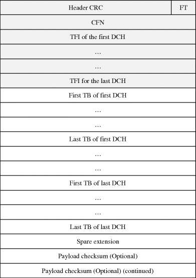
The fields are header crc, frame type (FT) for data or control frame, connection frame number (CFN), transport format indicators (TFI), transport blocks, Spare extension and an optional Payload checksum.
One MAC PDU maps into one transport block. Connection frame number informs of the first radio frame, where the transport block should be sent (downlink) or was received (uplink).
Both outer loop power control and scheduling of the transport blocks (scheduling by the MAC layer in the RNC), mean that the transport on the Iub is delay critical. FP control frame functionality is also used to indicate failures to higher layers (RRC). A failure may, via RRC actions, for example, cause termination of the Radio Bearer. A link break on the mobile backhaul is one example of such a failure case. Depending on timers and other implementation specific topics, this happens in 1 sec to few seconds, to even over 10 seconds.
MAC layer is the scheduling entity in the RNC. A transport format defines the format that the physical layer offers for MAC layer, for the delivery of a transport block set during a TTI. A transport format set consists of transport formats associated to a transport channel. A transport format indicator tells the physical layer, which transport format to use. Scheduled bit rate is varied by modifying the transport formats, or the attributes of it. The attributes include transport block size, transport block set size, TTI, error protection, and CRC.
Additional MAC functionality is ciphering. With transparent RLC mode, MAC layer also supports ciphering.
3.3.5 HSDPA (HS-DSCH) and HSUPA (E-DCH)
HSDPA and HSUPA change the functional split within the UTRAN. Radio interface scheduling is moved to the NodeB, and, due to link adaptation and faster scheduling, there is no need for fast power control from the RNC. Higher order modulation is also supported, increasing the bit rate.
Figure 3.17 HSDPA introduced.

A new mac-hs (MAC high speed, see Figure 3.17) scheduling entity is included in the NodeB. Scheduling takes place every 2 ms, as opposed to 10 ms in Rel-99 DCH (or, multiples of 10 ms) where scheduling is done in the RNC. Channel quality indication (CQI) is received from the terminal to the mac-hs scheduling entity in the NodeB. The scheduler of the NodeB is now able to rapidly adjust to the varying air interface channel conditions, using link adaptation.
HSDPA supports a shared channel in the downlink. With HSDPA, a single user may get instantaneous high capacity for her data, after which another user is served. This approach fits packet switched services much better than the use of dedicated channels. Reading a web page may take 30 seconds, after which another page is requested. During the reading time, resources are given to transmit data to other users.
Scheduling algorithms include round robin, best C/I (Carrier/Interference), and weighted fair scheduling. Round robin is fair, since all users get a share of the bandwidth. However, simple round robin does not take into account channel conditions, and air interface capacity is not necessarily well utilized. Scheduling according to the best Carrier/Interference uses air interface capacity efficiently, but fairness among users may suffer. Weighted fair scheduling aims at combining efficiency and fairness.
HSDPA supports both non-guaranteed bit rate and guaranteed bit rate bearers. Guaranteed bit rate service allows streaming and conversational service. Background traffic use non-guaranteed bit rate. With non-guaranteed bit-rate, a nominal bit-rate is still defined.
MAC-hs in the NodeB includes the H-ARQ (Hybrid Automatic Repeat Request) function. NodeB is able to retransmit packets that are lost on the air interface. This leads to faster retransmissions and subsequently better performance. For the Iub backhaul the requirements originating from the RNC are now somewhat relaxed compared to Rel-99 DCHs. For the end user experience on HSPA based services, low latency at the Iub however remains essential.
While packets lost in the air interface do not need to be retransmitted from the RNC, packets that are lost at the Iub are still retransmitted by the RLC layer in the RNC (assuming an acknowledged mode RLC).
To the FP layer on the Iub, HSDPA introduces HS-DSCH capacity request and capacity allocation messages (HSDPA Iub flow control). NodeB allocates the amounts that can be sent from the RNC over the Iub. The target is that the MAC entities in the NodeB and in the RNC select packets that can be sent to the MAC-hs function. Capacity allocation defines the amount of data allowed in terms such as number of PDUs, interval during which the granted capacity is to be transmitted, and a maximum PDU size.
With 16-QAM modulation, the RLC data rate is over 13 Mbit/s per user (Category 10 terminal, 15 codes used). This is further enhanced with MIMO (Multiple input, multiple output), 64-QAM modulation, and a possible use of multiple 5 MHz carriers. (Recall that the rate with four carriers achieves 168 Mbit/s.) Even the data rates with the 16-QAM resulting in data rates over 10 Mbit/s are more than a decade larger than what is achievable with the DCH. (Assuming 384 kbit/s DCH for the comparison).
Considering a NodeB air interface upgraded to HSDPA, depending on the configuration and other factors, it means that the site can source well over 10 Mbit/s traffic to the Iub backhaul. HSDPA, as well as 3G in general, allows dimensioning the Iub transport separately from the air interface capacity. The supported Iub capacity may be less than what is the available peak data rate in the air interface. Clearly then congestion may occur, and Iub traffic types need to be prioritized so that control channels and real-time services (voice) are not impaired during congestion. HSPA service may be poor, however, due to the heavy congestion on the Iub. For HSDPA Iub dimensioning, see [40] with further references.
If the Iub has not been upgraded accordingly, it easily becomes a severe capacity bottleneck. In good radio conditions, the capacity allocations given based on the HSPA air interface exceed the available Iub capacity. In this situation, the throughput is poor, due to congestion on the Iub. Air interface capacity has been expanded with HSPA, but this will not lead to higher data rates for the users, unless the mobile backhaul is similarly expanded.
While congestion cannot be removed without ultimately adding Iub capacity, a congestion control function has been defined in 3GPP to address the topic. This can significantly improve the performance with a narrowband Iub. With HSDPA congestion control, delay and loss can be detected over the Iub between the NodeB and the RNC. HSDPA congestion control functions over the Iub, and addresses the backhaul bottleneck. This is discussed further in the QoS chapter.
During the introduction of the HSDPA, many of the existing NodeBs were backhauled with ATM Iub over E1/T1/JT1s, compliant with 3GPP Rel-99. Due to the need for higher HSDPA data rates, and cost pressures, adding E1/T1/JT1s is often not feasible economically. An alternative is to offload HSDPA traffic into a parallel IP/Ethernet path, meaning that HSDPA is mapped into an IP path while other traffic remains on ATM. This also relieves the congestion discussed previously. The approach is illustrated in Figure 3.18.
Figure 3.18 Use of IP/Ethernet to backhaul high speed data.
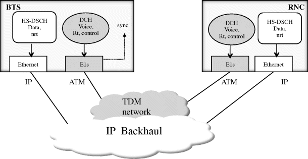
In 3GPP viewpoint this is a single logical Iub interface, where different traffic types comply with different transport protocol options: HSDPA is implemented with 3GPP Rel-5 IP transport, and Rel-99 DCH and control traffic (such as NBAP) with the Rel-99 ATM protocol stack.
HSDPA increased the data rates in downlink. High speed uplink packet access (HSUPA) in 3GPP Rel-6 introduced an E-DCH (enhanced DCH) to bring data speed improvement for the uplink transmission from the UE to the NodeB. E-DCH is still a dedicated channel as the name implies. E-DCH however borrowed the support of H-ARQ and fast MAC scheduling (10 ms, and 2 ms) from the HSDPA. As a dedicated channel, it has fast power control, and also supports soft handovers.
With HSUPA, the mac-e scheduler in the NodeB aims to achieve a high utilization, without causing an excessive noise rise in the cell.
Over the Iub, Frame protocol layer capacity requests and capacity allocations are supported, as well as a HSUPA congestion control functionality.
3.3.6 Iub
3G RAN (Radio access network) architecture is shown in Figure 3.19.
Figure 3.19 Interfaces of and within UTRAN [37].

Each NodeB connects to the RNC via an Iub interface. From a transport point of view, all traffic from the NodeBs is directed to the RNC. Physical transmission topology of the Iub interface, and for the NodeB access, is not shown in the figure. Typically, the transmission topology is different from that of the radio network logical topology.
RNC interfaces the core network with the Iu interface (Iu-cs, Iu-ps, Iu-BC and Iu-pc). Iu-cs is the interface to the circuit-switched core, Iu-ps interfaces the packet-switched core, Iu-BC is for interfacing Cell Broadcast Centre (CBC), and Iu-pc interfaces Standalone Serving Mobile Location Centre (SAS). The RNC may be connected to BSS supporting GERAN Iu mode via the Iur-g interface.
From the mobile backhaul perspective, Iub, Iur, Iu-ps and Iu-cs are the interfaces that are discussed further, as these are typically always implemented in the UTRAN.
3G Iub interface initially used ATM as defined in 3GPP Rel-99. In 3GPP Rel-5, IP transport was introduced. ATM based protocol stacks for user and control plane are shown in Figure 3.20.
Figure 3.20 ATM based Iub interface [54], [58].
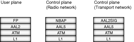
With the 3GPP initial Rel-99 standard, user plane traffic is carried over AAL2/ATM. Each user bearer maps to an AAL2 CID (Channel identifier), and these AAL2 bearers are set-up using AAL2 signaling. The AAL2 signaling VCC (Virtual Circuit Connection) is carried over AAL5/ATM. ATM allows separating traffic into VCCs of different characteristics, such as Constant Bit Rate (CBR), real-time Variable Bit Rate (rt-VBR) and Unspecified Bit Rate (UBR).
With ATM narrowband time-division-multiplexed E1, T1, JT1 interfaces are often used. Multiples of these physical interfaces can be combined with ATM IMA (Inverse Multiplexing over ATM). Also Sonet/SDH interfaces can be used with ATM.
ATM Iub can be emulated over the IP backhaul. ATM Virtual Circuits are, for example, mapped into MPLS pseudowires, or alternatively, the whole interface (E1/T1/JT1) traffic is mapped into a MPLS pseudowire.
Native IP based protocol stacks for user and control plane are shown in Figure 3.21 for the Iub interface.
Figure 3.21 IP Iub [54], [58].
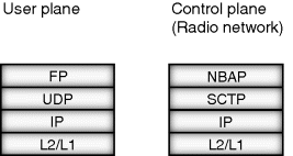
Frame protocol is the user plane radio network layer protocol carried on top of the transport layer (UDP/IP transport in the figure). Each user plane bearer is mapped into an UDP port and an IP address. With IP, the user plane bearers over the Iub (UDP/IP connectivity) are established via NBAP signaling. There is no need for a transport specific signaling protocol like AAL2 signalling in the case of ATM. In the bearer set-up phase, the receiving node informs the IP address into which the bearer shall be terminated.
SCTP/IP is used for NBAP. NBAP is the control plane protocol for the radio network signaling between NodeB and the RNC. NBAP procedures are needed e.g. to bring up and manage the cells. The same SCTP association is used for uplink and downlink directions, and bearers are mapped into a single stream in the uplink, and to a single stream in downlink direction. RFC3309 defined checksum shall be used.
Operation of the NBAP is critical for the NodeB. If IP connectivity is lost, SCTP times out (value depending on the parameters, e.g. after several seconds to tens of seconds) and consequently radio network layer recovery actions are started. The recovery may be a reconfiguration or a restart of the NodeB, which causes a service outage on that NodeB site.
For the IP layer, 3GPP Rel-5 defines IPv6 as mandatory, while IPv4 is optional, for all UTRAN terrestial interfaces. However, a note mentions that this shall not preclude a single implementation of IPv4. IP addresses of the mobile network elements do not need to be publicly routable, so there is typically no pressing need for IPv6 from an addressing viewpoint. Private IPv4 addresses can be used.
For the data link layer, 3GPP UTRAN specifications require that with the IP transport option, PPP with HDLC framing shall be supported. However a note adds that a single implementation of any other Layer-2 protocol is not precluded. As a conclusion, for UTRAN both IPv4 and IPv6 is allowed and the underlying layers (Layer-2, Layer-1) are not defined.
With the introduction of HSDPA and HSUPA, the Iub transport protocol stack is not modified. Use of HSDPA and HSUPA is in standardization not coupled to the introduction of the IP transport. In practice, the data rates often require an expansion of the backhaul network – which then leads to the introduction of IP transport. To the FP layer, new HS-DSCH Frame protocol and E-DCH frame protocol formats are introduced with HSPA.
3.3.7 Iur
Iur interface connects the RNCs to the neighbour RNCs. Protocol stacks for the IP based Iur is shown in Figure 3.22. IP protocol stack was included into the standard in 3GPP Rel-5. Prior to that, Iur is ATM based (3GPP Rel-99 definition).
Figure 3.22 IP based Iur [50], [54].

3.3.8 Iu-cs
Iu-cs interface connecs the UTRAN to the circuit-switched core network. Protocol stacks for the IP based Iu-cs are shown in Figure 3.23. IP protocol stack was included into the standard in 3GPP Rel-5. Prior to that, the Iu-cs is ATM based (3GPP Rel-99 definition).
Figure 3.23 IP Iu-cs [41].
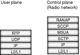
In the user plane, RTP protocol is used, over the UDP/IP. As a difference to A over IP protocols, RTP multiplexing is not defined for the Iu-cs. In the control plane, RANAP is mapped into the SIGTRAN protocol stack, SCCP/M3UA/SCTP/IP.
User plane bearer IDs, including IP addresses, are exchanged via the RANAP. In the bearer set-up phase the receiving node informs of the IP address into which the bearer shall be terminated.
3GPP defines IPv6 as mandatory, while IPv4 is optional, for all UTRAN terrestrial interfaces. However, a note mentions that this shall not preclude a single implementation of IPv4.
For the data link layer, 3GPP specifications require that with the IP transport option, PPP with HDLC framing shall be supported. However a note adds that a single implementation of any other Layer-2 protocol is not precluded. As a conclusion, for UTRAN both IPv4 and IPv6 is allowed and the underlying layers (Layer-2, Layer-1) are not defined.
3.3.9 Iu-ps
Iu-ps interface connects the UTRAN to the packet-switched core network. Protocol stacks for the IP based Iu-ps is shown in Figure 3.24. IP protocol stack was included into the standard in 3GPP Rel-5. Prior to that, the Iu-ps is ATM based (3GPP Rel-99 definition).
Figure 3.24 IP Iu-ps [41].

3GPP Rel-5 IP specifications define IPv6 as mandatory, while IPv4 is optional, for all UTRAN terrestrial interfaces. However, a note mentions that this shall not preclude a single implementation of IPv4.
User plane bearer IDs, including IP addresses, are exchanged via the RANAP. In the bearer set-up phase the receiving node informs into which IP address the bearer shall be terminated.
For the data link layer, 3GPP UTRAN specifications require that with the IP transport option, PPP with HDLC framing shall be supported. However, a note adds that a single implementation of any other Layer-2 protocol is not precluded (as defined in 3GPP TS25.414). As a conclusion, for UTRAN both IPv4 and IPv6 are allowed and the underlying layers (Layer-2, Layer-1) are not defined.
3.3.10 GTP-U Protocol
GTP-U (GPRS Tunneling Protocol) tunnels user IP from/to the RNC, over the Iu-ps interface. GTP protocol has two variants, GTP-U (user plane), and GTP-C (control plane). GTP-C protocol is not needed in the radio access network. Additionally, there are different versions of the protocol. For GTP-U, v1 is mandated in Rel-8 and onwards and the GTP-Uv1 specification is TS29.281. Before Rel-8, the normative reference of GTP-U is 3GPP TS29.060. GTP-v1 protocol does not need to listen to GTPv0, a well-known port 3386, and GTPv0 messages can be silently ignored.
A GTP-U tunnel is identified using a Tunnel Endpoint Identifier (TEID), IP address, and UDP port number. The UDP destination port number for GTP-U is 2152. The UDP source port is locally allocated by the sending node.
TEID value is exchanged by the radio network control plane protocol, RANAP. One GTP-U protocol entity exists for an IP Address. TEID allows multiplexing users, different packet protocols and different QoS levels. Different GTP-U Endpoints use different TEID values.
At the Iu-ps interface, 3GPP TS 29.281 defines that IPv4 shall be supported, and IPv6 should be supported. The Iu interface specification, 3GPPTS 25.414 defines that with the IP transport option, the RNC/core network node shall support IPv6, while the support of IPv4 is optional. A note adds that a single implementation of IPv4 is not precluded. There is seemingly contradiction, however, in practice it is a question of interoperation between RAN and core network, and on selecting a common protocol.
Figure 3.25 shows the GTP-U header.
Figure 3.25 GTP-U header [70].

The header is at minimum 8 bytes, as the fields that are always present are the version field, protocol type (PT), a Spare Bit (marked*, sent as ‘0’ and not evaluated by the receiver), extension header flag (E), sequence number flag (S), N-PDU number flag (PN), Message type, Length and Tunnel Endpoint Identifier. Optional header fields are sequence number, N-PDU number, and next extension header type.
Version field defines the version of the protocol, with GTP-U v1, the number is ‘1’. Protocol type differentiates between GTP (value ‘1’) and GTP' (value ‘0’) protocols.
Flags E, S, and N, indicate the presence of the corresponding headers, E for Extension header, S for Sequence number, and PN for N-PDU Number field.
GTP-U Message Types are shown in Figure 3.26.
Figure 3.26 GTP-U message types [70].

Length field means the length of the payload in octets. The optional header fields are considered payload.
Tunnel endpoint identifier, TEID, identifies the endpoint in the receiving entity. The TEID value is assigned locally by the receiving side.
For the optional fields, Sequence number is for preserving transmission order. N-PDU number field is used in coordinating acknowledged mode communication and needed in inter SGSN routing area update and with certain inter-system handover cases. Next extension header type defines the type of the extension header that follows.
GTP-U messaging supports both signalling messages and user plane G-PDU messages. Signalling messages are intended for user plane path/tunnel management. User plane messages, G-PDUs, carry the original packets, T-PDUs.
For the signalling messages, Echo request and Echo response can be used to detect that the peer is alive. The frequency of the messages is implementation specific. Supported extension header notification message indicates which extension headers are supported. Error indication is defined e.g. to inform of a received GTP-U PDU, which does not have a valid context (RAB in the case of Iu-ps). End marker indicates the end of a payload stream of tunnel. G-PDUs arriving on the tunnel after the end marker may be silently discarded.
User plane message (G-PDU) structure is GTP-U header, followed by a T-PDU. T-PDU is the inner IP packet in the GTP-U packet. The inner IP packet is an IP packet sent to the terminal in the downlink direction from the external network (identified by the APN), or, in the uplink direction, an IP packet sent from the terminal to the external network. One or more tunnels may be used.
3GPP TS TS23.060 defines the maximum inner IP packet size that can be transmitted without fragmentation in the terminal or GGSN, to be 1502 octets (for PDP of type PPP), or 1500 octets (for other cases). For the MTU calculation of the Iu-ps links (outer IP packet), IP, UDP, and GTP-U headers have to be taken into account in order to avoid fragmentation. Fragmentation is avoided, if links can be configured to support the required outer packet MTU.