8.6.1 Bearers and Their Attributes
End-to-end service in 3G, with the related bearers is shown in Figure 8.11. The attributes of the UMTS bearers are listed in Table 8.5.
Figure 8.11 3G bearers [35].
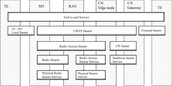
Table 8.5 UMTS bearer service attributes [35].
| Attribute | Description |
| Residual bit error rate (BER) | Indicates the undetected BER in the delivered SDUs. If no error detection is requested, residual BER indicates the BER in the delivered SDUs. |
| SDU format information | Indicates the exact size of SDUs |
| Sdu error rate | Indicates the fraction of SDUs lost or detected as erroneous. |
| Delivery of erronous SDUs | Indicates whether erroneous SDUs are delivered, or discarded. |
| Max SDU size | Maximum SDU size for which the network shall satisfy the negotiated QoS. |
| Delivery order | Defines whether the UMTS bearer provides in-sequence SDU delivery, or not. |
| Transfer delay | Maximum delay (95th percentile of the distribution of delay) for all delivered SDUs during the bearer service. |
| Traffic class | Defines the type of application for which the bearer service is optimized. Values: conversational/streaming/interactive/background |
| Traffic handling priority (THP) | Relative importance of SDUS compared to SDUs of other bearers within interactive class. Values: 1, 2 or 3. Used in scheduling, as an alternative to absolute guarantees. |
| Allocation and retention priority (ARP) | Priority of the bearer, for admission control and pre-emption. Based on subscription. Values 1,2, ..., 15. |
| Maximum bit rate | Maximum of bits delivered in a period of time. Upper limit a user or a application can accept or provide. |
| Guaranteed bit rate | Number of bits guaranteed to be delivered in a period of time. Service attributes (e.g. delay) are guaranteed up to the GBR. |
| Source statistics descriptor | Defines specific characteristics of the source of submitted SDUs (e.g. speech) |
| Signalling indication | Indicates the signalling nature of submitted SDUs, only for interactive class. |
Core network sets up the radio access bearers, and during the set-up procedure by RANAP (Radio Access Network Application Protocol), QoS parameters are signalled to the Radio network (to the RNC). These parameters indicate the required QoS for the new RAB.
The list of attributes in Table 8.5 is quite long. For HSPA, the system is simplified by specifying a scheduling priority indicator (SPI), which is carried over the Iub to the NodeB-SPI is used in the air interface scheduling, and also for mapping of the HSPA traffic into transport DSCPs.
8.6.2 Iub
Channels that are carried over the Iub are shown in Figure 8.12.
Figure 8.12 Traffic channels over the Iub.
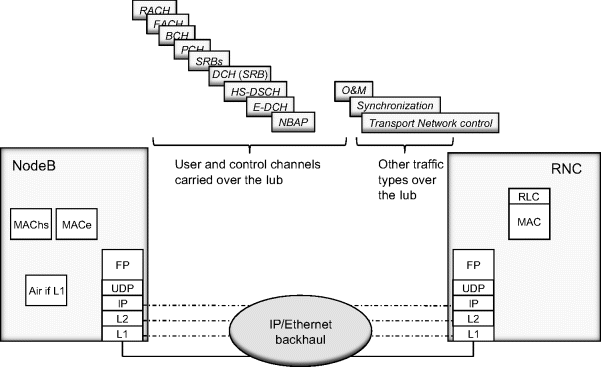
In addition to user channels (DCH, E-DCH, HS-DSCH), common channels (RACH, FACH, BCH, PCH), radio network signaling (NBAP), O&M and synchronization is needed over the Iub. Radio network signaling also is carried in SRBs which are DCHs.
For the transport network itself, control traffic like routing protocols and Ethernet layer control protocols, may exist.
User data can be further classified, starting from a division into CS/PS domains and traffic class. THP and ARP parameters can be taken into account, as well as SPI for HSPA channels. SPI information element is included into the NBAP signaling. SPI is an integer value between 0 (Lowest priority) and 15 (Highest priority), and indicates the relative priority of the HSDPA or HSUPA data frames. SPI is set by the RNC, and used in the air interface scheduling by the NodeB.
Figure 8.13 shows the radio network traffic types divided into HSDPA, HSUPA, Rel-99 PS and CS domains, and into common channels. In the mobile backhaul from the RNC to the NodeB, the received parameters are used as an input to mark the Diff Serv code point field in the IP packet in the RNC.
Figure 8.13 Example of mapping between radio and transport QoS.
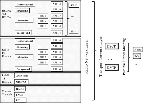
Additionally, SRB DCHs and NBAP signaling channels need to be mapped, as well as O&M, synchronization, and possible routing protocols and other IP control plane packets. Furthermore, the Diff Serv code point may be mapped into the Ethernet 802.1Q p-bits field, when Ethernet is used at the L2.
The IP layer QoS information in the Diff Serv field, derived as explained, may then be used in the ingress policing and egress scheduling/shaping functions in the mobile backhaul network elements. Allocation and retention priority (ARP) may be used by the RNC e.g. in deciding which bearers should be released in case of resource shortage. Guaranteed bit rate information can be used in admission control and related resource reservations in the mobile system, including transport interfaces, by the mobile network elements.
The bearer service attributes are not visible for the mobile backhaul directly. The backhaul elements identify the intended QoS from the packet marking done by the RNC in the downlink direction. In the uplink direction, NodeB marks packets similarly for transport over the backhaul network.
With HSPA, Frame protocol layer now includes a flow control function (credit allocation) between the NodeB and RNC. In the downlink (HSDPA) direction, NodeB allocates credits to the RNC, according to the air interface resource availability. When air interface has room for more HSDPA packets, the NodeB gives RNC further credits, which are consumed when the packets have been received over the Iub interface at the NodeB. The algorithms for credit allocation are not defined by 3GPP.
FP Flow control is a way of controlling the amount of information that needs to be transmitted over the Iub interface, based on the air interface resource situation. Another feature, HSDPA congestion control, additionally has the means of detecting and informing that there is congestion over the Iub interface. HSDPA congestion control detects both delay build-up and packet loss. HSDPA and HSUPA congestion control are discussed in a dedicated section.
In transport the delay increase is attributable to the buffer levels of the transport elements, typically to the egress buffer. Within mobile backhaul, the first buffers on the transport layers exist at the mobile elements, NodeB and RNC. Depending on the mobile backhaul type, further buffers typically are found in all packet network elements, IP routers, multilayer switches, Ethernet switches, and congestion may occur at any of these elements.
8.6.3 Iub Example
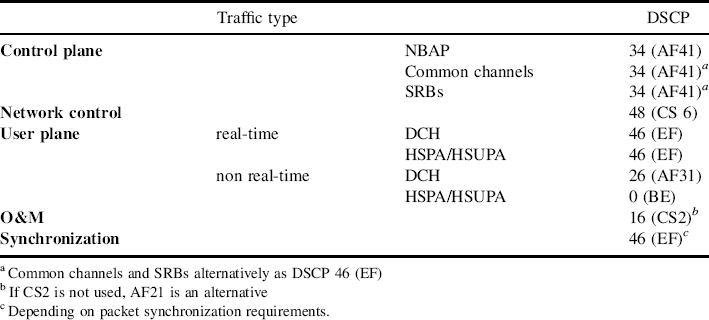
An example QoS mapping for an IP based Iub interface is considered in this section, by mapping control plane, network control, user plane, O&M and synchronization into the DSCPs for the transport service.
8.6.3.1 Control Plane (NBAP, Common Channels, SRBs)
Radio network signaling does not require a constant bandwidth. However, failing to service radio network signaling on common channels and on SRBs causes issues at the radio network level. Delays on radio network signaling impact call set-up/bearer set-up times and operation of handovers, the success rates for these, etc. These are difficult to trace to the backhaul, as radio network impairments are another potential cause. For mapping the QoS in the mobile backhaul, this dependency is a specific consideration.
The radio network control plane on NBAP is marked with DSCP 34 (AF41). The service for common channels (RACH, FACH, PCH,..) and signaling (SRBs) may be marked similarly with DSCP 34 (AF41), assuming however that adequate transport service is provided by the AF41 PHB.
For a stronger guarantee especially for common channels and SRBs, DSCP 46 (EF) can be used. This ensures that radio network signaling receives a guaranteed throughput. By this, the risk of compromising radio network performance due to delays and packet loss in the transport layer service is minimized. Traffic volume on SRBs and common channels is typically not high.
8.6.3.2 Network Control
Network control (e.g. routing protocols) is marked with a DSCP value of 48 (CS 6). This helps to ensure that the transport service and the backhaul network itself stays operational, can recover rapidly from failures, and maintain the transport service for the radio network layer.
8.6.3.3 User Plane
In the user plane, bearers are either Rel-99 DCH or HS-DSCH (HSDPA) and E-DCH (HSUPA) bearers. DCH in general has more stringent requirements on delay and jitter than HSPA and HSUPA. This is due to the network architecture and the location of radio network layer protocols.
However, HSDPA also includes a mac scheduling function in the RNC. HSUPA supports macrodiversity combining and fast power control in the RNC. Data from a UE is received via several NodeBs and should arrive at the same time to the RNC. This means in practice, that user traffic on HSPA still has radio network originated requirements for the Iub backhaul, even though the fast scheduling (mac-hs, mac-e) function is located in the NodeB.
Often the data volume in the uplink is lower than in the downlink. As backhaul typically provides symmetrical bandwidth in downlink and uplink directions, congestion rarely occurs in the uplink.
As presented in Figure 8.13, user traffic may be divided into a CS and a PS domain. Further, the PS domain is categorized into Conversational/Streaming/Interactive/Background. A starting point is a division into real-time and non real-time traffic types. The amount of data traffic is growing faster than the amount of voice traffic, therefore the amount of NRT traffic dominates the amount of RT traffic.
For the non-real time traffic, new WCDMA mobile phones typically provide the ability to use HSPA. Therefore it can be expected that more and more NRT traffic will use HSPA radio bearers instead of NRT DCHs. Also, it can be assumed that a substantial amount of background NRT traffic exists on HSPA bearers. This elastic traffic can be used to reduce bandwidth requirements on the transport network by statistical multiplexing.
In this example user plane is mapped to three different treatment aggregates:
- All real-time traffic, whether Rel99 or HSPA, is marked with DSCP 46 (EF).
- Non real-time traffic on Rel 99 dedicated channels is marked with DSCP 26 (AF31).
- Non real-time traffic on HSPA is marked with DSCP 0 (BE).
8.6.3.4 O&M
O&M traffic is marked with DSCP 16 (CS2). A special characteristic of the mobile network O&M traffic is that occasionally the traffic volume is high, while on average it is much lower. Consider a SW download as an example of high data transfer needs. On average the amount of traffic is low. As alarms are transferred via the O&M channel, a minimum capacity is needed for the O&M, so that this information can be forwarded.
8.6.3.5 Synchronization (by Packet)
How synchronization is obtained, is subject to implementation. Synchronization was discussed in Chapter 6. Even with a standardized approach for packet timing, e.g. IEEE1588v2, algorithms are implementation specific. These may differ with respect to their requirements for the backhaul. A constant bit stream is served by an EF class.
A specific issue is delay jumps. If delay changes abruptly (which could happen in a recovery after a failure), algorithms may react differently, again depending on the implementation.
As an example, assuming IEEE1588v2, the traffic can be marked with DSCP46 (EF) to treat it with a deterministic throughput and low delay.
Table 8.6 presents this as a summary.
Table 8.6 DSCP marking for the Iub.
8.6.3.6 Summary
In the transport network each treatment aggregate could be mapped to a separate queue, based on the DSCP marking of the packets. If four or less queues are available, then network control and real-time traffic could be mapped to the same queue. O&M traffic could be mapped either to the same queue as non real-time Rel99 traffic or as to the queue with non real-time HSPA traffic. Either strict priority schedulers or WRR/WFQ schedulers can be used.
A further topic is in mapping different classes of users in the radio network and in the backhaul. Approaches for the backhaul are easily vendor specific, as there is no guidance by 3GPP. A starting point is the radio network layer ARP parameter.
8.6.4 Congestion Control in MBH
Despite the capabilities of the backhaul transport protocols (resilience, high data rate, low latency, QoS differentiation, etc.), transient congestion may occur due to the capacity limited first mile links such as microwave radio or due to the overbooking of the high capacity aggregation links.
During congestion, connections experience increased delay, reduced throughput and packet drops. TCP is the dominant transport protocol used by the majority of data applications; it has its own efficient congestion control mechanism that reacts by reducing the rate of the connections and by retransmitting the data that is assumed to be lost. Adaptive video streaming applications are also able to adapt their rate to the available bandwidth.
In full packet based systems such as LTE, these end-to-end mechanisms might be enough but not for HSPA. Transport congestion deteriorates the overall HSPA system performance as it can trigger unnecessary RLC AM (Radio Link Control Acknowledged Mode) retransmissions as dropped packets are retransmitted by the RLC AM entity. Moreover, in cases where the transport is shared by the LTE and HSPA traffic, congestion may cause fairness problems as HSPA traffic is not TCP friendly and thus LTE connections can starve.
Although the functionality of the HSPA systems has been extended by 3GPP with a means of detecting congestion at the RNC and Node B and with the capability of notifying the source node that congestion has occurred, the congestion control algorithm itself is not specified. Detection and indication are possible via additional IEs (Information Elements) included in the HS-DSCH and E-DCH frame protocols' data frame headers or via special control frames. LTE has no similar standardized functionality.
8.6.5 Congestion Control in HSPA Systems
Data applications such as file transfer or web browsing are TCP based, which provides error free delivery of the data. The TCP congestion control mechanism was developed based on the assumption that the bit errors caused by the physical media imperfections are very unlikely thus the transport congestion is the only reason for data loss in the system. This is true for wired systems but not for radio links, where bit and block errors are frequent. The TCP mechanisms do not handle data loss well due to air interface imperfections. In legacy WCDMA systems, the user plane traffic between the RNC and Node B is mostly carried over dedicated transport channels via the Iub and Iur interfaces.
To overcome the negative impact of the air interface errors on the data traffic, NRT (non-real-time) bearers (carrying data traffic) are handled by the RLC AM entities (one is located in the RNC and the other is in the UE) that have an ARQ mechanism responsible for retransmitting the missing (lost) data in case negative acknowledgement (NACK) is received from the peer RLC AM entity. As the RLC AM entities are located in the RNC and the UE, there is a significant latency (referred to as Layer 2 Round Trip Time) in the reaction time to air interface errors or packet drops on the transport network that has a negative impact on the TCP performance.
Transport congestion is hidden from the TCP as the RLC AM entity retransmits the missing data. In-sequence delivery, another feature of the RLC AM, prevents the RLC AM entity at the receiver side from delivering any correctly received consecutive TCP segment to the upper layer before the missing data is received or the incorrectly received TCP segment is discarded. That is, in case the maximum number of allowed retransmissions is reached, the corresponding TCP segment (that is, the RLC AM SDU) is discarded and the RLC continues with a consecutive TCP segment. If that is successful, a duplicate ACK is sent to the TCP source that might already be in slow start due to timeout caused by the long latency of the RLC retransmission mechanism. In order to improve the system performance, i.e., to minimize the amount of retransmissions, the transport should be dimensioned so that the likelihood of transient congestion is low. This results in an over-dimensioned and costly transport network.
HSPA has introduced additional system features (fast scheduling, adaptive coding and modulation, HARQ, HSDPA flow control) and Iub protocols (MAC-hs, MAC-e, MAC-es) that improve the system performance in terms of data rates and latency.
The role of the HARQ mechanism is to reduce the latency of the Layer 2 retransmissions due to air interface errors: it executes retransmissions when negative acknowledgements are received or when the acknowledgement is not received in time. This mechanism handles the air interface errors efficiently, but packet drops due to transport congestion are still handled by the RLC AM entity residing at the RNC and UE. On the other hand, the HSDPA flow control algorithm considers only the air interface (when the capacity allocations are calculated) thus it can easily overload the transport network causing congestion and eventually packet drops. This leads to performance degradation as packet drops at the transport network trigger RLC AM retransmissions.
HSDPA/HSUPA congestion control functionality was proposed by 3GPP TR25.902 with the scope to handle the efficiency problems caused by transport congestion. The approach was to reuse the existing network features and, despite the technical differences, to provide similar solutions in HSUPA and HSDPA.
The congestion control entity is located at the Node B as in both HSDPA and HSUPA it controls the rate of the connections either via capacity allocations sent to the SRNC (HSDPA) or via grants issued to the UEs (HSUPA).
The congestion detection is based on additional information attached to each frame sent in UL or DL: a reference time that indicates the time when the frame was sent and a sequence number. The reference time is used in order to detect delay build-up whereas the sequence number is used in order to detect frame loss. Delay build-up indicates that the frames are queued in transport buffers due to overload whereas the frame loss indicates that the frames are dropped due to overload. The role and functionality of the Iub protocols during a web page download over HSDPA is shown in Figure 8.14.
Figure 8.14 The role of the Iub protocols during a web page download over HSDPA.

8.6.6 HSDPA Congestion Control
The HSDPA congestion control functionality is located at the Node B as a complementary mechanism to the already existing HSDPA flow control functionality of the MAC-hs layer that defines the rate of the MAC-d flows via capacity allocation messages sent to the SRNC. The reference time and sequence number enables the Node B to detect downlink transport congestion, based on which information the congestion control mechanism calculates the amount of resources granted to the MAC-d flows.
The rate of the MAC-d flows is controlled via the HS-DSCH FP Capacity Allocation Control Frames sent to the SRNC through the Iub interface. There are two types of control frames: HS-DSCH Capacity Allocation Control Frame Type 1 and Type 2. Type 2 was introduced with the Flexible RLC, whereas Type 1 is used in earlier releases with fixed RLC. This message contains the allocation that the SRNC may use, i.e., the following IEs: Maximum MAC-d PDU Length Type1/Type 2, HS-DSCH Credits and HS-DSCH Interval. Additionally, the HS-DSCH Repetition Period IE (within both Type 1 and Type 2 control frames) defines the validity period of the allocation. If its value is set to zero, it means that the allocation can be repeated without a limit.
A further possibility is to inform the SRNC about the detection of congestion in the downlink direction by setting the Congestion Status bits within the Capacity Allocation Control frame. The possible values of the 2 bits carrying the congestion status are: no TNL congestion (0), TNL congestion detected by delay build-up (2), TNL congestion detected by frame loss (3), whereas value 1 is reserved for future use.
The Maximum MAC-d PDU Length IE indicates the maximum allowed PDU size from the MAC-d PDU sizes configured via RNSAP (Type 1 frames) or it is a factor in the granted amount of MAC-d PDU data the SRNC may transmit during one HS-DSCH Interval (Type 2 frames). In the latter case, the amount of data is obtained by multiplying the content of the MAC-d PDU Length Type 2 IE with the content of the HS-DSCH Credits IE.
An HS-DSCH Credits IE value set to zero means that no resources are allocated to MAC-d flows and the transmission should be stopped. In case of Type 1 frames the content of the IE indicates the amount of PDUs the SRNC is allowed to transmit during one HS-DSCH Interval, whereas in case of Type 2 frames the IE is used when the granted amount of MAC-d PDU data is calculated, as described above.
The HS-DSCH Interval IE indicates the scheduling interval of the allocated amount of data at the SRNC. The first interval starts right after the reception of the allocation, subsequent intervals start after the first interval elapsed, until the number of intervals specified by the HS-DSCH Repetition Period IE is reached.
The capacity allocation messages are sent either as a response to an HS-DSCH Capacity Request sent from the SRNC or whenever the HS-DSCH flow control or congestion control algorithm decides to reduce or increase the rate of a particular connection. The amount of allocations should be calculated so that the air interface resources are not wasted, i.e., when the packet scheduler selects a bearer/connection for scheduling, there is enough data in the connection's buffer at the Node B, but on the other hand this buffer is not overloaded and at the same time the transport congestion is reduced.
At each HS-DSCH scheduling interval, the SRNC schedules the amount of MAC-d PDU data specified in the last HS-DSCH Capacity Allocation control frame. The MAC-d PDUs are sent in HS-DSCH FP data frames (Type 1 and Type 2, respectively) that contain the FSN and DRT information elements and the buffers' status report (size) included into their headers. The FSN is incremented for each HS-DSCH data frame of a given MAC-d flow. The length of the IE is four bits where the value zero is not used at wraparound. The DRT (length 16 bits) is a 40960 counter with 1 ms resolution. In addition the FP data frame header contains an FSN/DRT reset bit; when it is set, the Node B should reset any state of congestion estimation based on earlier FSNs and DRTs.
HS-DSCH Capacity Request control messages are sent by the SRNC whenever the SNRC considers that the buffer status needs an increased reporting frequency, i.e., to signal an event such as data discard or arrival, compared to the buffer reporting via data frames. The request can be sent in order to trigger reconsideration of the allocation size, for example in the case of zero allocation when the SRNC side buffer content is increasing or when after a longer idle period new data has arrived at the SRNC.
An example of HSDPA congestion control architecture is provided in Figure 8.15.
Figure 8.15 An example HSDPA congestion control architecture.

8.6.7 HSUPA Congestion Control
Similarly to the HSDPA, the HSUPA Congestion Control functionality is located in the Node B, whereas the detection functionality is located in the SRNC. The congestion information is signaled to the Node B with the E-DCH FP Congestion Indication Control Frame.
Figure 8.16 An example HSUPA congestion control architecture.

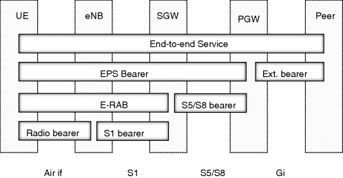
Figure 8.17 Bearers in LTE [42].
The MAC-e (air interface) packet scheduler at the Node B calculates the allocation (serving grant) sent to the UEs based on the congestion information received from the SRNC. This allocation defines when and with which bit rate the UEs are allowed to transmit in the cell. The received data is assembled into E-DCH Data Frames with the following congestion control related IEs: frame sequence number (FSN), connection frame number (CFN) and sub-frame number. The FSN IE is incremented by one (modulo 16) for each transmitted data frame. The CFN indicates the radio frame when the HARQ process correctly decoded the data. In the case of 10 ms HSUPA TTI, the delay is calculated by the SRNC based on the CFN. When the HSUPA TTI is 2 ms, the same CFN is shared among five sub-frames; therefore the sub-frame number is used to calculate the delay variation between consecutive frames.
In order to detect congestion, the SRNC analyzes the content of the relevant IEs of the received E-DCH FP Data Frames: a packet discard on the transport is detected by following the value of the FSN IE of the consecutive data frames of the same connection, whereas delay build-up is detected by calculating the delay or delay variation based on the content of the CFN or sub-frame IEs.
The congestion status is signaled to the Node B via E-DCH FP Congestion Indication Control Frames that can indicate that the congestion is over (or there is no congestion on the transport network) or that there is congestion. The reason for congestion, i.e., whether delay build-up or frame loss was detected is signaled with different reason codes included in the congestion status messages.
The Node B reduces at least the rate of the MAC-d flow for which the congestion indication control frame was received. After the congestion is over, the rate of the MAC-d flows is gradually increased. An example of HSUPA congestion control architecture is provided in Figure 8.16.
8.6.8 Co-existence of Radio Networks
In most of the cases LTE systems will be deployed in order to provide additional radio access possibilities to the already existing WCDMA/HSDPA systems thereby creating heterogeneous coverage over the same areas and providing the possibility of offloading the data traffic from the WCDMA/HSDPA systems. Heterogeneous radio access networks will use the same packet based transport infrastructure, i.e., limited transport resources will be shared by WCDMA/HSDPA and LTE systems. Transport links carrying the traffic of the co-existing radio access systems might experience transient congestion.
The HSDPA Congestion Control located in the Node B will detect the congestion based on the delay measurements and sequence number of the HS-DSCH transport frames and it will take action in order to solve the congestion by reducing the rate of the connections. The feedback loop of the HSDPA congestion control is short. In most of the cases, the transport congestion will be transparent to the TCP congestion control mechanism.
In case of LTE, transient congestion is detected by the TCP congestion control mechanism. The rate of the connections is controlled by the round trip time. In the case of single packet drops, the TCP fast retransmit and fast recovery algorithms retransmit the missing TCP segment and halve the rate of the connections. In cases of severe congestion, when no acknowledgement is received before the TCP timeout timer expires, the TCP source transits into slow start phase and retransmits the data for which an acknowledgement was not received.
As the HSDPA congestion control feedback loop is shorter than the end-to-end TCP flow/congestion control loop, the rate of the connections using HSDPA is reduced first. The unused bandwidth will be taken by TCP connections over LTE. This will continue until the total starvation of the HSDPA connections.
When the HSDPA congestion control is not applied, the rate of the HSDPA connections is controlled by the HSDPA flow control mechanism that aims to achieve optimal air interface usage without considering the transport congestion. The HSDPA data traffic in this case is not TCP friendly as upon congestion the data rate of the MAC-d flows is not reduced but the lost data is retransmitted by the RLC AM entities. In cases where the congested link is shared by HSPA and LTE, this will cause the starvation of the TCP connections over LTE. Moreover, turning the HSDPA congestion control off in homogeneous networks or when there is only HSDPA traffic in the system can lead to inefficient resource utilization due to RLC AM retransmissions even if there are no other connections but HSDPA.
As the topic is not addressed in 3GPP, solving the co-existence efficiently becomes an implementation issue, and different solutions exist.
