In the previous nine chapters, you learned about AVX, AVX2, and AVX-512. You also acquired the programming skills necessary to code C++ SIMD functions that exploited these x86 instruction set extensions to significantly accelerate the performance of a wide variety of algorithms. The chapter that you are about to read commences the second half of this book, which covers x86-AVX SIMD programming using x86-64 assembly language.
Unlike higher-level languages such as C and C++, a software developer must understand critical architectural details about the target processor before attempting to write any assembly language code. The goal of this chapter is to impart enough architectural information that will enable you to code x86-64 assembly language functions that utilize the computational capabilities of AVX, AVX2, and AVX-512. It begins with a section that explains x86 data types. This is followed by a section that succinctly describes the internal architecture of an x86-64 processor. The final three sections cover x86-64 instruction operands, memory addressing modes, and condition codes.
The goal of the next nine chapters is to teach you how to code x86-AVX SIMD functions using x86-64 assembly language. This is an ambitious objective given the breadth and legacy of the x86 platform. To keep the forthcoming explanations and source code examples focused on the stated goal, I have intentionally excluded some secondary topics (e.g., advanced string processing, bit manipulation instructions, and x86 microarchitectures) that are normally examined in an x86 assembly language programming book. You can read about these topics in my earlier book, Modern X86 Assembly Language Programming, Second Edition. You can also consult the AMD and Intel programming reference manuals listed in Appendix B for more information regarding the minutiae of x86 processor architecture and assembly language programming.
Like the earlier chapters, the remainder of this book uses the acronyms AVX, AVX2, and AVX-512 when explaining features or instructions exclusive to these technologies. The term x86-AVX is used as an umbrella expression for SIMD capabilities or resources common to all three instruction set extensions. The expressions x86-32 and x86-64 signify 32-bit and 64-bit processors or execution environments, while the term x86 applies to both. The remaining discussions in this and all subsequent chapters assume that you have a basic understanding of SIMD principles and are versed with AVX, AVX2, and AVX-512 programming using C++ SIMD intrinsic functions. If you feel your comprehension of these topics is lacking, you may want to review the relevant chapters in the first half of this book before proceeding.
Data Types
Functions written in x86-64 assembly language can use a wide variety of data types. Most of these types originate from a small set of fundamental data types that are intrinsic to the x86 platform. A programmer can employ these fundamental data types to perform arithmetic and data manipulation operations using signed and unsigned integers, single-precision and double-precision floating-point values, text strings, or SIMD operands. The remainder of this section describes the x86 data types that are used in x86-64 assembly language functions.
Fundamental Data Types
Fundamental Data Types
Data Type | Size (Bits) | Typical Use |
|---|---|---|
Byte | 8 | Characters, small integers |
Word | 16 | Characters, integers |
Doubleword | 32 | Integers, single-precision floating-point |
Quadword | 64 | Integers, double-precision floating-point, memory address |
Double Quadword | 128 | Integers, packed integers, packed floating-point |

Bit-numbering and byte-ordering schemes for x86-64 fundamental data types
A fundamental data type is properly aligned in memory when its address is an integral multiple of its size in bytes. For example, a doubleword is properly aligned when it is stored at a memory address that is an integral multiple of four. Similarly, a quadword is properly aligned when it is stored at a memory address that is evenly divisible by eight. Unless enabled by the host operating system, an x86-64 processor does not require fundamental data types to be properly aligned in memory. However, it is standard programming practice to properly align all values whenever possible to avoid potential performance penalties that can occur when the processor accesses an improperly aligned data value in memory.
Numerical Data Types
X86-64 Numerical Data Types
Type | Size (bits) | C++ Type | <cstdint> |
|---|---|---|---|
Signed integer | 8 | char | int8_t |
16 | short | int16_t | |
32 | int, long | int32_t | |
64 | long, long long | int64_t | |
Unsigned integer | 8 | unsigned char | uint8_t |
16 | unsigned short | uint16_t | |
32 | unsigned int, unsigned long | uint32_t | |
64 | unsigned long, unsigned long long | uint64_t | |
Floating point | 32 | float | n/a |
64 | double | n/a |
In Table 10-2, note that the size of a C++ long and unsigned long varies. 64-bit versions of Linux use 64-bit wide integers for both long and unsigned long, while 64-bit versions of Windows use 32-bit wide integers for these same types.
SIMD Data Types
The X86 SIMD data types are described in Chapter 1. You can refer to this chapter if you need to refresh your understanding of these types.
Strings
An x86 string is a contiguous block of bytes, words, doublewords, or quadwords. The x86-64 instruction set includes instructions that perform string compare, load, move, scan, and store operations. X86-64 string instructions also can be employed to carry out processing operations using arrays, bitmaps, or similar contiguous-block data structures. For example, the instruction movsb (Move Data from String to String) is often used to copy data bytes from one buffer to another, while the instruction stosb (Store String) can be used to set each element in an array to zero or some other constant value.
Internal Architecture
General-purpose registers
Instruction pointer
RFLAGS register
Floating-point and SIMD registers
MXCSR register

X86-64 processor internal architecture
General-Purpose Registers

X86-64 general-purpose registers
The low-order doubleword, word, and byte of each 64-bit general-purpose register are independently accessible and can be used to carry out operations using 32-, 16-, or 8-bit wide operands. For example, a function can use registers EAX, EBX, ECX, and EDX to perform 32-bit integer arithmetic in the low-order doublewords of RAX, RBX, RCX, and RDX, respectively. Similarly, registers AL, BL, CL, and DL can be used to perform 8-bit calculations in the low-order bytes. It should be noted that the Intel programming reference manuals use different names for some of the byte registers. This book uses the same register names as the Microsoft 64-bit macro assembler (MASM) to maintain consistency between the text and source code. Not shown in Figure 10-3 are the legacy byte registers AH, BH, CH, and DH. These registers are aliased to the high-order bytes of registers AX, BX, CX, and DX, respectively.
Despite their designation as general-purpose registers, the x86-64 instruction set imposes some notable restrictions on their use. Several instructions either require or implicitly use specific registers as operands. This is a legacy scheme inherited from the 8086 that ostensibly improves code density. For example, some variants of the imul (Multiply Signed Integers) instruction save the calculated product in RDX:RAX, EDX:EAX, DX:AX, or AX. The colon notation used here signifies that the final product is stored in two registers with the first register holding the most significant bits. The idiv (Divide Signed integers) requires the integer dividend to be loaded in RDX:RAX, EDX:EAX, DX:AX, or AX. The x86-64 string instructions use registers RSI and RDI for the source and destination buffers, respectively; string instructions that employ a repeat (or length) count must load this value into register RCX.
The processor uses register RSP to support stack-based operations such as function calls and returns. The stack itself is simply a contiguous block of memory that is assigned to a process or thread by the operating system. Programs can use the stack to preserve registers, pass function arguments, and store temporary results. Register RSP always points to the stack’s top-most item. Stack push and pop operations are performed using 64-bit wide operands. This means that the location of the stack should always be aligned on a quadword (8-byte) boundary. Some 64-bit runtime environments (e.g., Visual C++ programs running on Windows) align stack memory and RSP to a double quadword (16-byte) boundary to improve performance when loading or storing stack-based SIMD values.
Register RBP is frequently used as a frame pointer that can reference data items or local storage on the stack. If a function does not require a frame pointer, RBP can be used as a general-purpose register. You will learn more about the stack and frame pointers in Chapters 11 and 12.
Instruction Pointer
The instruction pointer register RIP contains the logical address of the next instruction to be executed. The processor automatically updates the value in RIP during the execution of each instruction. RIP is also updated during execution of a control-transfer instruction. For example, the call (Call Procedure) instruction pushes the contents of RIP onto the stack before transferring program control to the specified address. The ret (Return from Procedure) instruction transfers program control by popping the top-most eight bytes off the stack and loading them into the RIP register.
The jmp (Jump) and jcc (Jump if Condition is Met) instructions also transfer program control by modifying the contents of RIP. Unlike the call and ret instructions, x86-64 jump instructions are executed independent of the stack. Register RIP is also used for displacement-based operand memory addressing as explained later in this chapter. It is not possible for an executing function to directly access the contents of register RIP.
RFLAGS Register
RFLAGS Register
Bit Position | Name | RFLAGS Symbol | Use |
|---|---|---|---|
0 | Carry Flag | CF | Status |
1 | Reserved | 1 | |
2 | Parity Flag | PF | Status |
3 | Reserved | 0 | |
4 | Auxiliary Carry Flag | AF | Status |
5 | Reserved | 0 | |
6 | Zero Flag | ZF | Status |
7 | Sign Flag | SF | Status |
8 | Trap Flag | TF | System |
9 | Interrupt Enable Flag | IF | System |
10 | Direction Flag | DF | Control |
11 | Overflow Flag | OF | Status |
12 | I/O Privilege Level Bit 0 | IOPL | System |
13 | I/O Privilege Level Bit 1 | IOPL | System |
14 | Nested Task | NT | System |
15 | Reserved | 0 | |
16 | Resume Flag | RF | System |
17 | Virtual 8086 Mode | VM | System |
18 | Alignment Check | AC | System |
19 | Virtual Interrupt Flag | VIF | System |
20 | Virtual Interrupt Pending | VIP | System |
21 | ID Flag | ID | System |
22–63 | Reserved | 0 |
For application programs, the most important status bits in RFLAGS are the following flags: carry flag (RFLAGS.CF), overflow flag (RFLAGS.OF), parity flag (RFLAGS.PF), sign flag (RFLAGS.SF), and zero flag (RFLAGS.ZF). Some arithmetic instructions use the carry flag to signify an overflow condition when performing unsigned integer arithmetic. It is also used by some rotate and shift instructions. The overflow flag signals that the result of a signed integer operation is too small or too large. The processor sets the parity flag to indicate whether the least-significant byte of an arithmetic, compare, or logical operation contains an even number of “1” bits (parity bits are used by some communication protocols to detect transmission errors). The sign and zero flags are set by arithmetic and logical instructions to signify a negative, zero, or positive result.
RFLAGS contains a control bit called the direction flag (RFLAGS.DF) that is used by x86 string instructions. An application program can set or clear the direction flag, which defines the auto increment direction (0 = low to high addresses, 1 = high to low addresses) of the RDI and RSI registers during execution of a string instruction. Reserved bits in RFLAGS should never be modified, and no assumptions should ever be made regarding the state of any reserved bit.
Floating-Point and SIMD Registers

AVX/AVX2 register set
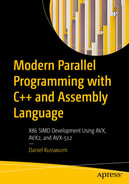
Scalar floating-point values in an XMM register
Not shown in Figure 10-2 is the legacy x87 floating-point unit (FPU). An x86-64 program can still use the x87 FPU to perform scalar floating-point arithmetic. However, the x87 FPU is normally not used in x86-64 programs since it is more efficient code-wise to use the XMM register set to carry out scalar floating-point arithmetic.

AVX-512 register sets
MXCSR Register
MXCSR Register Bit Fields
Bits | Symbol | Name | Description |
|---|---|---|---|
0 | IE | Invalid operation flag | Floating-point invalid operation error flag |
1 | DE | Denormal flag | Floating-point denormal error flag |
2 | ZE | Divide-by-zero flag | Floating-point division-by-zero error flag |
3 | OE | Overflow flag | Floating-point overflow error flag |
4 | UE | Underflow flag | Floating-point underflow error flag |
5 | PE | Precision flag | Floating-point precision error flag |
6 | DAZ | Denormals are zero | Enables automatic conversion of a denormal to zero |
7 | IM | Invalid operation mask | Floating-point invalid operation error exception mask |
8 | DM | Denormal mask | Floating-point denormal error exception mask |
9 | ZM | Divide-by-zero mask | Floating-point divide-by-zero error exception mask |
10 | OM | Overflow mask | Floating-point overflow error exception mask |
11 | UM | Underflow mask | Floating-point underflow error exception mask |
12 | PM | Precision mask | Floating-point precision error exception mask |
13–14 | RC | Rounding control | Specifies the method for rounding floating-point results; valid options include round to nearest (00b), round down toward -∞ (01b), round up toward +∞ (10b), and round toward zero (11b) |
15 | FZ | Flush to zero | Forces a zero result if the underflow exception is masked and a floating-point underflow error occurs |
16–31 | --- | Reserved | Reserved for future use |
Application programs normally do not directly modify the floating-point exception mask bits in MXCSR. However, most C++ runtime environments provide a library function that allows an application program to designate a callback function that gets invoked whenever a floating-point exception occurs. Application programs can modify the MXCSR’s rounding control bits, and you will learn how to do this in Chapter 12.
Instruction Operands
Nearly all x86-64 instructions use operands, which designate the specific values that an instruction will act upon. Most instructions require one or more source operands along with a single destination operand. Most instructions also require the programmer to explicitly specify the source and destination operands. There are, however, several instructions where register operands are either implicitly specified or required by an instruction as discussed earlier in this chapter.
Examples of X86-64 Instructions and Operands
Type | Example | Analogous C++ Statement |
|---|---|---|
Immediate | mov rax,42 | rax = 42 |
imul r12,-47 | r12 *= -47 | |
shl r15,8 | r15 <<= 8 | |
xor ecx,80000000h | ecx ^= 0x80000000 | |
sub r9b,14 | r9b -= 14 | |
Register | mov rax,rbx | rax = rbx |
add rbx,r10 | rbx += r10 | |
mul rbx | rdx:rax = rax * rbx | |
and r8w,0ff00h | r8w &= 0xff00 | |
Memory | mov rax,[r13] | rax = *r13 |
or rcx,[rbx+rsi*8] | rcx |= *(rbx+rsi*8) | |
mov qword ptr [r8],17 | *(long long*)r8 = 17 | |
shl word ptr [r12],2 | *(short*)r12 <<= 2 |
The mul rbx (Multiply Unsigned Integers) instruction that is shown in Table 10-5 is an example of an instruction that uses an implicit operand. In this example, implicit register RAX and explicit register RBX are used as the source operands, and implicit register pair RDX:RAX is the destination operand. The multiplicative product’s high-order and low-order quadwords are stored in RDX and RAX, respectively.
The qword ptr text that is used in Table 10-5’s penultimate example is an assembler operator that acts like a C++ cast operator. In this instruction, the value 17 is subtracted from the 64-bit value whose memory location is specified by the contents of register R8. Without the qword ptr operator, the assembly language statement is ambiguous since the assembler cannot ascertain the size of the operand pointed to by R8; the destination operand in memory could also be an 8-, 16-, or 32-bit value. The final example in Table 10-5 uses the word ptr operator in a similar manner. You will learn more about assembler operators and directives in subsequent chapters.
Memory Addressing
An x86 instruction requires up to four separate components to specify the location of an operand in memory. The four components include a constant displacement value, a base register, an index register, and a scale factor. Using these components, the processor calculates an effective address for a memory operand as follows:
Memory Operand Addressing
Addressing Form | Example |
|---|---|
RIP + Disp | mov rax,[Val] |
BaseReg | mov rax,[rbx] |
BaseReg + Disp | mov rax,[rbx+16] |
IndexReg * SF + Disp | mov rax,[r15*8+48] |
BaseReg + IndexReg | mov rax,[rbx+r15] |
BaseReg + IndexReg + Disp | mov rax,[rbx+r15+32] |
BaseReg + IndexReg * SF | mov rax,[rbx+r15*8] |
BaseReg + IndexReg * SF + Disp | mov rax,[rbx+r15*8+64] |
The memory addressing forms shown in Table 10-6 facilitate the referencing of simple variables, elements in an array, or members in a data structure. For example, the simple displacement form is often used to access a single global or static value. The base register form is analogous to a C++ pointer and is used to indirectly reference a single value. Individual fields within a data structure can be retrieved using a base register and a displacement. The index register forms are useful for accessing a specific element in an array or matrix. Scale factors can reduce the amount code needed to access elements in an array or matrix. Elements in more elaborate data structures can be referenced using a base register together with an index register, scale factor, and displacement.

RIP-relative effective address calculation
One minor constraint of RIP-relative addressing is that the target operand must reside with a ± 2GB address window of the value in RIP. For most programs, this limitation is rarely a concern. The calculation of a RIP-relative displacement value is usually determined automatically by the assembler or linker. This means that you can use a mov rax,[Val] or similar instruction without having to worry about the details of the displacement value calculation.
Condition Codes
Condition Codes, Mnemonic Suffixes, and Test Conditions
Condition Code | Mnemonic Suffix | RFLAGS Test Condition |
|---|---|---|
Above Neither below nor equal | A NBE | CF == 0 && ZF == 0 |
Above or equal Not below | AE NB | CF == 0 |
Below Neither above nor equal | B NAE | CF == 1 |
Below or equal Not above | BE NA | CF == 1 || ZF == 1 |
Equal Zero | E Z | ZF == 1 |
Not equal Not zero | NE NZ | ZF == 0 |
Greater Neither less nor equal | G NLE | ZF == 0 && SF == OF |
Greater or equal Not less | GE NL | SF == OF |
Less Neither greater nor equal | L NGE | SF != OF |
Less or equal Not greater | LE NG | ZF == 1 || SF != OF |
Sign | S | SF == 1 |
Not sign | NS | SF == 0 |
Carry | C | CF == 1 |
Not carry | NC | CF == 0 |
Overflow | O | OF == 1 |
Not overflow | NO | OF == 0 |
Parity Parity even | P PE | PF == 1 |
Not parity Parity odd | NP PO | PF == 0 |
Note that Table 10-7 shows alternate forms for most mnemonic suffixes. These are defined to provide algorithmic flexibility or improve program readability. When using a conditional instruction such as jcc in source code, condition codes containing the words “above” and “below” are employed for unsigned integer operands, while the words “greater” and “less” are used for signed integer operands. If Table 10-7 seems a little confusing or abstract, don’t worry. You will see a plethora of condition code examples in the assembly language programming chapters of this book.
Summary
The fundamental data types of the x86-64 platform include bytes, words, doublewords, quadwords, and double quadwords. Programming language primitive data types such as characters, text strings, integers, and floating-point values are derived from the fundamental data types.
An x86-64 processor includes 16 64-bit general-purpose registers that are used to perform arithmetic, logical, and data transfer operations using 8-bit, 16-bit, 32-bit, and 64-bit operands.
An x86-64 processor also includes an instruction pointer (RIP) and control and status (RFLAGS) register. The former points to the next executable instruction; the latter contains processor control bits and status flags. Most arithmetic and logical instructions update one or more of the status flags in RFLAGS. These flags can be tested to alter program flow or conditionally assign values to variables.
X86-64 processors that support AVX/AVX2 include 16 256-bit wide registers named YMM0–YMM15. The low-order 128 bits of each YMM register can be referenced as XMM0–XMM15.
X86-64 processors that support AVX-512 include 32 512-bit wide registers named ZMM0–ZMM31. The low-order 256 bits/128 bits of each ZMM register is aliased to a corresponding YMM/XMM register. AVX-512-compliant processors also include eight opmask registers that facilitate merge masking and zero masking.
A function can use the ZMM, YMM, and XMM registers to carry out SIMD operations using packed integers or packed floating-point values. The XMM registers can also be used to perform scalar floating-point arithmetic using single-precision or double-precision values.
The MXCSR register contains control bits that select options for floating-point operations and exceptions. This register also contains status bits that report floating-point error conditions.
An operand in memory can be referenced using a variety of addressing modes that include one or more of the following components: fixed displacement, base register, index register, and/or scale factor.
Most x86-64 assembly language instructions can be used with the following explicit operand types: immediate, register, and memory. Some instructions employ implicit registers as their operands.