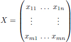
3
Codes and Watermarks
Pascal LEFÈVRE1, Philippe CARRÉ1 and Philippe GABORIT2
1 XLIM, CNRS, University of Poitiers, France
2 XLIM, CNRS, University of Limoges, France
In this chapter, we propose to analyze the principle of digital watermarking of images through the prism of the use of error-correcting codes in a very specific framework, namely the so-called robust watermark. The process of watermarking can be studied according to the formality of the transmission of information in a possibly noisy channel. These error-correcting codes have demonstrated their value in this type of application, which is why they were quite naturally introduced in the context of watermarking. In this chapter, classical Hamming error-correcting codes as well as Bose-Chaudhuri-Hocquenghem (BCH) codes and Reed–Solomon (RS) codes are associated with random and packet error structures. In order to illustrate the impact and benefit of using error-correcting codes, we deploy a simple use case based on by index modulation watermarking. In particular, we discuss the differences in behavior regarding robustness, according to the attack and the code used. We conclude the chapter by introducing a more original code and show how a specific code can respond to a particular problem, here the problem of cropping.
3.1. Introduction
Over the years, several watermarking paradigms have emerged due to the protection requirements of many applications. It is very easy to modify or falsify images because of public access to image processing software. Checking the integrity and authenticating an image are therefore important issues. In this context, the idea of the fragile watermark is to insert a pattern so that any modification of the image changes the pattern. The modified regions can therefore be detected by analyzing this pattern. The disadvantage of this watermarking paradigm is that it is not possible to distinguish between content modified inadvertently or with good intentions, and content that has been maliciously modified. For example, the oldest methods classify a compressed image in the category of falsified images, yet its semantics have not changed. Examples of work can be found in previous studies (Yeung and Mintzer 1997; Wolfgang and Delp 1999; Khan et al. 2014; Bravo-Solorio et al. 2018; Shehab et al. 2018). A similar paradigm is semi-fragile watermarking. Work on semi-fragile watermarking (Lu et al. 2003; Ho and Li 2004; Maeno et al. 2006) has been developed in order to distinguish malicious modifications from those that are not.
These two approaches clash with the principle of robust watermarking which aims to resist image modifications. In fact, so-called robust techniques aim to resist all types of image modifications in order to extract information without error. The error-correcting code tool will be positioned in this context of robust watermarking, since the function of the code is to correct the errors and therefore remove the influence of the attacks on the image. Therefore, first of all, we propose to introduce robust watermarking, which is the framework this chapter is centered around: the error-correcting codes aim to improve robustness in the face of various attacks.
In the following, after recalling the context of robust watermarking (section 3.2) and index modulation (section 3.3), we present section 3.4, classical Hamming error-correcting codes as well as BCH codes and RS codes. In sections 3.5 and 3.6, we discuss a simple use case based on watermarking by index modulation applied to color images. In section 3.7, we analyze the differences in behavior concerning robustness according to the attack undergone and the code used. This chapter concludes (section 3.8) with the introduction of a more original code, and we show how a particular code can answer a particular problem.
3.2. Study framework: robust watermarking
In this chapter, we will concentrate on so-called robust watermarking, which constitutes the classical application framework for the use of codes in watermarking. Many applications, such as copyright protection, require the perfect extraction of a mark inserted in an image that has been modified. In practice, a digital watermarking method will “survive” an attack to a certain extent and it is believed that when an image is too deteriorated, the extraction of the mark loses its value.
The robust watermarking paradigm allows a three-step scenario: inserting the mark into a host image, the transmission of the marked image in a noisy channel (noisy due to an attack on the watermarked image) and finally, the detection step. We detail each step in this section. Note that this formulation through the idea of noisy channels gives full meaning to the introduction of codes. In order to simply explain the use of error-correcting in a watermarking framework, we describe the classical outline of insertion and detection.
We show the classical diagram of insertion of a mark in Figure 3.1. Image χ, chosen as the host of the mark, can be of different types, that is, in grayscale or in color (defined in the RGB color space or other color spaces). Depending on the methods, image χ can be represented in a space other than the original spatial domain (frequency coefficients, wavelet coefficients). From the transformed image χ′, coefficients noted as ![]() χ are chosen with the extraction function Extr (random selection of the insertion sites, decomposition of the entire image) because of the secret key k.
χ are chosen with the extraction function Extr (random selection of the insertion sites, decomposition of the entire image) because of the secret key k.

Figure 3.1. Classical diagram of watermark insertion
Then, the message m is inserted by modifying Cχ in the watermarking area, which is only accessible with the key k to cut off access to this area. The coefficients ![]() are then reintegrated into the transformed image and we get a marked image
are then reintegrated into the transformed image and we get a marked image ![]() with the inverse transformed Tr−1.
with the inverse transformed Tr−1.
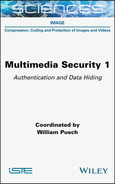
In the second step of this scenario, the image marked ![]() is transmitted through a noisy channel
is transmitted through a noisy channel ![]() (Figure 3.2). The noise n represents the possible different attacks on a channel (e.g. compression and noise). Here, we see the parallel that can be drawn with the framework for analyzing the transmission of information.
(Figure 3.2). The noise n represents the possible different attacks on a channel (e.g. compression and noise). Here, we see the parallel that can be drawn with the framework for analyzing the transmission of information.
Without any other “preparation” of the message, the robustness of the information hidden in front of a given attack depends on several criteria.
At the detection stage (Figure 3.3), we access the watermark channel because of the extraction function Extr and the key k of image ![]() . Then, we apply the planned detection method to the coefficients
. Then, we apply the planned detection method to the coefficients ![]() . If the power of the attack is reasonable, the estimate m′ is the same as m.
. If the power of the attack is reasonable, the estimate m′ is the same as m.
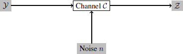
Figure 3.2. Diagram of the transmission of an image in a channel affected by noise

Figure 3.3. Classical diagram of detection of a mark
The insertion area can be chosen according to the attack that the mark must resist. Changing the representation of the image makes it possible to take advantage of certain properties of resistance to certain attacks. For example, naively, resistance to an attack of the filtering type can be obtained by modifying the frequency coefficients corresponding to the low frequencies. Another essential point to consider is the synchronization of the mark; in other words, the choice of the insertion sites in an image. If the attacks we are facing have an influence on the position of the coefficients, it is necessary to take this into account at the insertion (and detection) stage. In some cases, the choices for insertion space and synchronization are not that different. For example, in the spacial domain, inserting information on pixels representing the edge areas (choice of coefficients according to a fixed property) can be equivalent to inserting information in high frequencies.
For the following, in order to more precisely illustrate the impact of the use of error-correcting codes on a watermarking method, we propose the use of a quantization strategy called index modulation (or QIM) (Chen and Wornell 1999b) for its performance when combined with error-correcting codes.
3.3. Index modulation
In 1999, Chen and Wornell proposed index modulation (or the QIM method) to perform watermarking by quantization. This algorithm is known for its ease of implementation and its low cost of calculation, but also for its fragility in the face of scaling attacks. Pérez-González et al. (2005) suggest an improvement called Rational Dither Modulation to better resist this last attack. Chen and Wornell have also proposed variations, such as Dither Modulation (DM) QIM and Distortion Compensated (DC) QIM as well as an associated theoretical study. The DMQIM method is an adaptation of the QIM method which moves the quantification cells with a random vector (Zamir and Feder 1994; Chen and Wornell 1999b). The modified values are more difficult to identify and make access to the watermarking channel more difficult. The DCQIM method is composed of a processing step added after the QIM quantification in order to improve the invisibility/robustness compromise. The authors also propose a vector variation called Spread Transform Dither Modulation, which consists of quantifying the projection of the sample vectors on a direction axis. Chen and Wornell proposed a second extension of the QIM method called Lattice QIM (Moulin and Koetter 2005), a method that we have chosen to use in this chapter for its regular structure (Euclidean network) and its robustness potential, previously associated with error-correcting codes. There are many contributions using the QIM method and its variations (e.g. Eggers et al. (2000a); Bas et al. (2003); Wang and Lin (2004); Oostveen et al. (2004); Li and Cox (2007); Abdul et al. (2013)).
In the next part of this chapter, we propose to study the Lattice QIM (LQIM) method.
3.3.1. LQIM: insertion
The quantization space of this method is a Euclidean lattice ![]() of dimension L where a host sample x ∈
of dimension L where a host sample x ∈ ![]() L is transformed into an element y from this network. The scalar QIM method is the special case L = 1.
L is transformed into an element y from this network. The scalar QIM method is the special case L = 1.
The sample x is made by selecting coefficients from the image. To insert a bit of information, L pixel values are selected in the image. For example, a strategy of random selection of these values can be adopted. These insertion sites are secret and only accessible to the sender and the receiver because of a secret key.
To insert a bit of information m ∈ {0, 1}, x is quantized by y belonging to one of the following subsets called cosets denoted by Λ0 and Λ1 defined as:
thanks to the following quantization function ![]() :
:
with Δ the quantization step of the method.
Figure 3.4 is an example of quantization in dimension L = 2 of vector x. For any cross or circle with center ym, the dotted diamonds define the boundaries of each quantization cell. On insertion, x is transformed into the nearest ym in Euclidean distance.
3.3.2. LQIM: detection
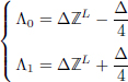
On reception of an image, which has been marked and then modified, the message can be detected by extracting the coefficients used for insertion using the secret key. To extract the information bit m, the coset closest to the associated z vector is calculated to determine the estimate ![]() such that:
such that:
with the Euclidean norm, ‖.‖2.
The detection equation [3.3] is illustrated with Figure 3.4.
In this section, we have described the insertion and detection part of Figures 3.1 and 3.3. In the case of a real application, the transformation Tr and the method of extracting coefficients or synchronization must also be selected. A simple example is the insertion in the spatial domain with random extraction of pixels. In section 3.4, we propose to tackle the integration of error-correcting codes more specifically in digital watermarking strategies.
3.4. Error-correcting codes approach
Error-correcting codes are powerful tools in information theory. They are used to resolve problems to do with signal transmission in noisy channels (not reliable). Robust digital watermarking can be seen as a transmission issue. In this chapter, we intend to review how error-correcting codes can be integrated into watermarking strategies in order to improve robustness against certain attacks. Depending on the attack encountered, the errors produced may have a particular structure and therefore one error-correcting code may be more effective than another. The next part of this section is dedicated to a brief overview of the BCH (Bose and Ray-Chaudhuri 1960) and RS (Reed and Solomon 1960) codes, which are Hamming codes (Hamming 1950).

Figure 3.4. Representation of the quantization space (or Euclidean network) in dimension L = 2. The symbol + represents bit 1 (coset Λ1) and ◦ represents bit 0 (coset Λ0)
3.4.1. Generalities
When data are transmitted in a channel, transmission errors can occur. The role of error-correcting codes is to correct these transmission errors. To protect this information, a code corrector adds repetition to a message so that errors can be detected and corrected after transmission. In Figure 3.5, we present a diagram illustrating the different stages of transformation and transmission of a message.

Figure 3.5. The different stages allowing the reliable transmission of a message in a channel
An encoding function is an injective application ϕ defined as:
with k being the dimension of the code and n being the length of the code.
ϕ designs a code of parameters (k, n). So a word (from the source) m ∈ {0, 1}k has a code word for an image c = ϕ(m) ∈ {0, 1}n. The encoding function ϕ is designed by Enc() (Figure 3.5). A code corrector is a set ![]() = Im(ϕ).
= Im(ϕ).
When a code word c′ is transmitted in a channel, it may contain errors. To correct these, a basic algorithm includes comparing the word received with the code words; in other words, the elements of ![]() , such that:
, such that:
to find c ∈ ![]() which is closest to c′, in the sense of Hamming distance.
which is closest to c′, in the sense of Hamming distance.
The word c′ is then decoded through the code word c.
Hamming distance is the number of distinct symbols between two words c1 and c2. It is defined by:
We also define Hamming weights as the number of symbols, that are not zero, of a word c. It is defined by:
Note that this basic algorithm takes a long time to finish because the number of comparisons made is exponential (complexity in ![]() (n2k)). If k is small, the decoding time is acceptable, but this becomes impractical when k is larger. When decoding, we implicitly assume that when the number of errors is low enough, the number of code words closest to c′ is equal to 1 (perfect codes).
(n2k)). If k is small, the decoding time is acceptable, but this becomes impractical when k is larger. When decoding, we implicitly assume that when the number of errors is low enough, the number of code words closest to c′ is equal to 1 (perfect codes).
Another important basic concept about correcting codes is the idea of minimal distance which represents the smallest distance between two code words of a ![]() code. It makes it possible to characterize the decoding power. A minimum distance code d is written as (n, k, d) and is capable of correcting t errors, such that:
code. It makes it possible to characterize the decoding power. A minimum distance code d is written as (n, k, d) and is capable of correcting t errors, such that:
There are codes with more structure, such as linear codes. A code is said to be linear if there is a matrix ![]() with k rows and n columns with coefficients in {0, 1} of rank = k, such that:
with k rows and n columns with coefficients in {0, 1} of rank = k, such that:
The linearity of a code gives image ![]() a vector subspace structure of {0, 1}. The minimal distance of a linear code d is therefore equal to the smallest non-zero Hamming weight of a code word of
a vector subspace structure of {0, 1}. The minimal distance of a linear code d is therefore equal to the smallest non-zero Hamming weight of a code word of ![]() . For a given linear code, it can be hard work to determine its minimal distance. However, there is an increase in this called the Singleton bound:
. For a given linear code, it can be hard work to determine its minimal distance. However, there is an increase in this called the Singleton bound:
When d = n − k + 1, the parameter code (n, k, d) is a code known as maximum distance separable(MDS).
![]() is called the generator matrix of ϕ. A linear code is also associated with the concept of control matrix. Control matrix
is called the generator matrix of ϕ. A linear code is also associated with the concept of control matrix. Control matrix ![]() of the code
of the code ![]() is defined as:
is defined as:
The main advantage of the linearity of a code is being able to build faster decoding algorithms. We have introduced the most important aspects of the basic concepts on corrective codes and give an overview of the BCH and RS codes in sections 3.4.3 and 3.4.4. First, we propose to study a particular construction widely used in watermarking: code concatenation.
3.4.2. Codes by concatenation
The robustness of a watermarking algorithm can be improved by using the principle of error correction by concatenation (Figures 3.6–3.8). In the context of watermarking, it is quite simply a question of using two concatenated codes: a so-called external coding or “outer coding”, which will be a simple coding by repetition, and an internal coding or “inner coding”, which will be a classical code like Hamming code, BCH or RS. During decoding, the repetition of the mark makes it possible to reduce the level of error (and can also provide certain properties such as robustness to cropping attacks) and the associated classical code will have the function of correcting the errors in order to be able to decide whether the signature received and reconstructed is valid or not. In fact, an error-correcting code cannot show its potential when the error level is too high, and therefore this repetition of the encoded signature makes it possible to improve the error rate of the channel and bring it to an acceptable level. In some cases, this allows interaction on Watermark channels at very high error levels (0.1 < BER < 0.5).
Figure 3.6 shows this principal of construction of the mark that we are going to insert from the signature to be hidden. The repeat setting is adaptive, depending on the size of the image and the signature.
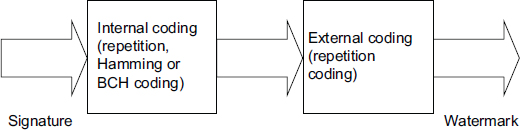
Figure 3.6. Strategy by “concatenation codes”

Figure 3.7. Decoding in the case of the code by “concatenation codes”
Obviously on reception, the opposite procedure is applied to decode the signature from the mark, as shown in Figure 3.7.
Figure 3.8 illustrates the complete diagram associated with the use of codes in the context of watermarking. First of all, a signature is created from a secret key. Then this signature is encoded through the internal encoding (in the example we use a simple 4-bit repetition code). Then the external coding is applied by repetition of the encoded signature, with a repetition parameter that depends on the size of the image or on the watermarking strategy (e.g. ROI encoding).

Figure 3.8. Illustration of the creation of a mark by code concatenation
Note that we are talking about repeating code because a repeating code simply consists of building the mark from the signature by repeating each code word n times. Decoding simply consists of an averaging operation for each code word received, in order to distinguish a 0 from a 1.
3.4.3. Hamming codes
Hamming codes are linear block codes. For an integer m > 1, we have the following representation for binary Hamming codes in the form (n, k, d) = (2m – 1, 2m – 1 – m, m).
For m = 3, we have Hamming codes of parameters (7, 4, 3). These Hamming codes code size 4 data bits in blocks of length 7 (Hamming code word). The additional 3 bits are parity bits. Each of these 3 bits represents the parity of 3 of the 4 data bits, and no parity bit represents the same data bits twice. All parity bits are even parity. The Hamming error-correcting code (7, 4, 3) can correct a 1-bit error in each of the Hamming code words.
For a linear code (n, k, d), the matrix of generator ![]() is a k × n matrix, for which the vector space generated is the code given. A parity-check matrix for a linear code (n, k, d) is a (n – k) × n H matrix, for which Hx = 0 for any style of code x.
is a k × n matrix, for which the vector space generated is the code given. A parity-check matrix for a linear code (n, k, d) is a (n – k) × n H matrix, for which Hx = 0 for any style of code x.
The generator matrix ![]() used in the making of Hamming codes is made up of I, the identity matrix and the parity-check matrix A, where
used in the making of Hamming codes is made up of I, the identity matrix and the parity-check matrix A, where ![]() = [I|A].
= [I|A].
The process of building the code is as follows.
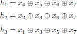
Let d1, d2, d3 and d4 be bits of data, and a Hamming code (7,4,3) can define parity bits p1, p2 and p3 such that:

We can now build the generator matrix ![]() from the Hamming code:
from the Hamming code:
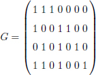
where the first, second and fourth bits are parity bits, respectively, and the third, fifth, sixth and seventh bits are data bits, respectively. This is specified by the following elements:

with (x1, x2, x4) and (x3, x5, x6, x7) denoting parity and data bits, respectively.
From the side of the recipient, we have the parity-check matrix ![]() given by h1, h2 and h3, where:
given by h1, h2 and h3, where:
If there is an error (assuming one at most), (h1h2h3) will be the binary representation of indications of incorrect bits. A binary Hamming code has a parity-check matrix, which has m column vectors. For the code with parameters (7, 4, 3), the parity-check matrix is:
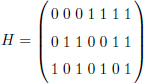
When we multiply the code word received by the parity-check matrix, we get the corresponding parity ranging from 000 to 111. These three bits give us the location of the error. The word 000 indicates that there was no transmission error, while non-zero words (001 through 111) indicate the location of the error relative to the seven received code word bits. We can then correct at most ![]() errors because the minimum Hamming distance between our code words is 7 − 4 = 3. We can therefore correct 1 error at most.
errors because the minimum Hamming distance between our code words is 7 − 4 = 3. We can therefore correct 1 error at most.
As soon as we know the location of the error, we can simply reverse the corresponding bit to correct the error. Next, we remove the parity bits from positions one, two and four to extract the message. The Hamming codes are perfect error correction codes 1. In other words, any word received including one error at most is decoded correctly and the code has the smallest possible size of all the codes, which correct a single error.
The Hamming codes that we used can correct an error in each code word and, additionally, they allowed us to simply introduce the concepts related to the use of the codes. However, it is necessary to study other types of codes that correct more errors. We have selected BCH codes, which are explained in section 3.4.4.
3.4.4. BCH codes
3.4.4.1. Cyclic block codes
Let ![]() be a linear block code over a finite field F of length n.
be a linear block code over a finite field F of length n. ![]() is called a cyclic code, if for each code word c = (c1, ..., cn) of
is called a cyclic code, if for each code word c = (c1, ..., cn) of ![]() , the word (cn, c1, ..., cn−1) of Fn obtained by a cyclic shift to the right of the components is also a code word of
, the word (cn, c1, ..., cn−1) of Fn obtained by a cyclic shift to the right of the components is also a code word of ![]() .
.
BCH codes are codes in cyclic blocks, such that for any positive integer m ≥ 3 and t with t ≤ 2m−1 − 1, there is a BCH code of length n = 2m − 1 able to correct t errors and of dimension k = n − m × t.
To go even further, we define some basic terminology.
- – Irreducible polynomial: we call a polynomial f(x) irreducible over K[x] if it has no proper divisors in the field K[x].
- – Primitive polynomial: the polynomial f(x) is primitive if it is irreducible of degree n > 1 and it is not a divisor of 1 + xm for all m < 2n − 1.
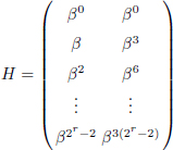
- – Galois field: for each primitive polynomial of order pm, there is a unique finite field of order pm denoted by
 is primitive if αm ≠ 1 for 1 ≤ m ≤ 2r − 1 and each non-zero word in GF(2r) can be expressed as a power of α.
In Table 3.1, the construction of GF(24) using the primitive polynomial h(x) = 1 + x + x4 is illustrated, where each vector is indicated as a power of β.
- – Minimal polynomial: the minimal polynomial of α is the polynomial K[x] of smallest degree admitting for root mα(x) where mα(x) is irreducible in K. If f(x) is any polynomial above K such that f(α) = 0, then mα(x) is a factor of f(x) and mα(x) is unique. mα(x) is also a factor of 1 + x2r−1. α is an element of F = GF(2r) and the order of α is the smallest positive integer m such that αm = 1 and α ∈ GF(2r) is a primitive element if there is order 2r − 1.
3.4.4.2. An example of construction: BCH (15,7,5)
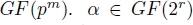
BCH error-correcting codes of length 2r − 1 (r ≥ 4) are defined by g(x) = mβ(x)mβ3(x). The generator polynomial gp(x) = m1(x)m3(x) is of degree 2r and the code has dimension n − 2r = 2r − 1 − 2r. β is a primitive element in GF(24) made with p(x) = 1 + x + x4, m1(x) = 1 + x + x4 and m3(x) = 1 + x + x2 + x3 + x4. Therefore, gp(x) = m1(x)m3(x) = 1 + x4 + x6 + x7 + x8 is the generator polynomial of BCH code (15, 7, 5) which, in turn, gives us the generator matrix ![]() :
:
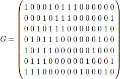
Table 3.1. Galois field GF(24)
| Word | Polynomial in x | Power of β |
|---|---|---|
| 0000 | 0 | − |
| 1000 | 1 | β0 = 1 |
| 0100 | x | β1 |
| 0010 | x2 | β2 |
| 0001 | x3 | β3 |
| 1100 | 1 + x = x4 | β4 |
| 0110 | x + x2 = x5 | β5 |
| 0011 | x2 + x3 = x6 | β6 |
| 1101 | 1 + x + x3 = x7 | β7 |
| 1010 | 1 + x2 = x8 | β8 |
| 0101 | x + x3 = x9 | β9 |
| 1110 | 1 + x + x2 = x10 | β10 |
| 0111 | x + x2 + x3 = x11 | β11 |
| 1111 | 1 + x + x2 + x3 = x12 | β12 |
| 1011 | 1 + x2 + x3 = x13 | β13 |
| 1001 | 1 + x3 = x14 | β14 |
H is the parity check matrix for error correcting codes BCH (15, 7, 5). It is defined by:
By using Table 3.1, we obtain the following parity-check matrix:

The decoding algorithm will then be constructed as follows:
- 1) calculate the syndrome wH = [s1, s3] = [w(β), w(β3)];
- 2) if s1 = s3 = 0, there are no errors;
- 3) if (s1)3 = s3, a single error in position i, where s1 = βi;
- 4) if s3 = 0 and s1 ≠ 0, two errors in positions (i + 5)%15 and (i + 10)%15, where s1 = βi;
- 5) constructing a quadratic equation:
BCH codes are designed for random errors. For packet errors, it can be more effective to use RS codes.
3.4.5. RS codes
3.4.5.1. Principle of RS codes
RS codes (Reed and Solomon 1960) are non-binary cyclic correcting codes whose symbols are made of m bits, where m > 2.
RS codes (n, k, d) of symbols containing m bits exist for all n, k and d satisfying the following conditions:
where k is the number of data symbols (in other words, the size of the code) to encode and n is the number of symbols in a code word (in other words, the size of the code):
where d is the minimal Hamming distance between the code words transmitted and received; in other words, the number of different symbols between the two words and t the capacity of the code correction. RS codes can correct any combination of up to t where t is given by:
3.4.5.2. Bounded distance decoding algorithms
Bounded distance decoding algorithms can correct up to t erroneous symbols. One of the algorithms (Justesen and Høholdt 2004) is illustrated in this section.
For a word received r = (r1, r2, ..., rn):
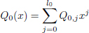
- 1) solve the following linear system:
with l0 = n − 1 − t and l1 = n − 1 − t − (k − 1) ;
- 2) write:
and:

- 3) calculate:
- 4) if g(x) ∈ F[x] then the corrected code word is cc = g(x1), g(x2), . . . , g(xn) if not, decoding fails.

3.4.5.3. Performance against packet errors of RS codes
RS codes are particularly useful against burst noise and they exhibit lower performance against errors that are random. This is illustrated in the following example.
Consider a (n, k, d) = (40, 11, 30) RS code, where each symbol is made up of m = 6 bits, as shown in Figure 3.9. As d = 30 indicates that this code can correct any t = 14 symbol error in a block of 40. Consider the presence of a burst of noise lasting 60 bits that disturbs 10 symbols, as shown in Figure 3.9. The RS (40, 11, 30) error correcting codes can correct any 14 symbol errors using the bounded distance decoding algorithm regardless of the type of error the attack induced.

Figure 3.9. Performance of RS codes against packet errors
The code corrects by blocks of 6 bits and replaces the whole symbol by the correct one without taking into account the number of corrupted bits in the symbol, that is, it treats an error of 1 bit in the symbol in the same way as it treats an error of 6 bits of the symbol, replacing them with the correct 6 bit symbol.
This gives the RS codes a tremendous burst noise advantage over binary codes. In this example, if the 60-bit noise disturbance can occur in a random fashion rather than as a contiguous burst, it could affect many more than 14 symbols, which is beyond the capability of the code. This shows the advantage of using RS codes to correct burst errors and their inability to correct random errors beyond a certain limit.
Any attack that affects the watermarked image in a random fashion might make the watermark decoding difficult for images watermarked using RS codes. In the watermarking channel, the errors, characterized by the different attacks, occur in random or burst manner. Depending on the placement of the watermark in an image and the use of error correcting codes, the robustness of the signature can be increased against the attacks.
Note that for RS codes, conventional bounded distance decoding algorithms correct up to ![]() symbol errors, as shown in the example above. By using list decoding, Sudan (1997) and later Guruswami and Sudan (1998) have shown that the RS’s error correction capability can be improved to
symbol errors, as shown in the example above. By using list decoding, Sudan (1997) and later Guruswami and Sudan (1998) have shown that the RS’s error correction capability can be improved to ![]() and
and ![]() , respectively, which makes then more effective against burst errors or errors in bulk.
, respectively, which makes then more effective against burst errors or errors in bulk.
To conclude, the integration of corrective codes in a digital watermarking strategy consists of inserting a code word in an image. Against a given attack, the question will be to choose the correction code that provides the best correction performance by observing the structure of the errors linked to this attack (block or random error, for example). However, using “classical” codes is not always the best strategy. For example, another error structure has recently been studied, associated with codes called rank-metric codes that are best for correcting this error structure. The works of Lefèvre et al. (2018, 2019) are the first contributions introducing rank-metric codes to improve the robustness of digital watermarking. These codes are different to classical Hamming codes because the metric corresponds to the rank of a matrix on a finite field and has the mathematical properties of a distance. We discuss these codes at the end of this chapter.
3.5. Contradictory objectives of watermarking: the impact of codes
The aim of robust watermarking is to optimize three properties in particular: the maximum amount of information that an image can contain, the invisibility of the mark (and preservation of the quality of the host content) and the robustness of the mark to image changes and, in some cases, security. This is why in recent years we have defined watermarking according to these four characteristics. However, in general, when one of these properties is improved, the others are degraded.
Watermarking requires a mark to be invisible to the naked eye and does not degrade the host content. To achieve this, the distortions between host content and marked content must be low enough. Ideally, a mark should be imperceptible to the human visual system (HVS), which is the subject of Chapter 4 of this volume, entitled “Invisibility”. This can also be invisible to a machine, in other words, a statistical invisibility, but it is a property that relates more to steganography than to digital watermarking. For the HVS, the perceptual approach of digital watermarking of images makes it possible to create insertion distortions in the areas of the image most sensitive to visual change. In Chapter 4, we discuss how we can take into account HVS sensitivity to minimize psycho-visual distortions to the insertion in the specific framework of color images. Concretely, the addition of an error correction code in the construction of the inserted mark does not have a direct impact on this idea of invisibility. It is obvious that the burying strategy is the main process influencing this invisibility. However, the introduction of a code that allows an increase in robustness can make it possible, in certain cases, to limit the “insertion force” parameter needed for the correct decoding of the signature, such as the parameter of quantification in the example that serves as a common theme. And so, we limit visual degradation indirectly.
The capacity is the maximum amount of useful information that the image to be marked can contain with respect to a given insertion method. In general, we always use binary symbols, but it is possible to encode the information on only two symbols. The more information we insert, the more the number of modified coefficients increases and the more the distortion increases. The quality of the marked image decreases.
To measure this amount, we can calculate the embedding rate in the spatial domain, such that:
with 1 being the bit number of the message, and the denominator is the number of modified pixels for image χ of size m × n.
The unit of this measurement is bit per pixel. We can also make the same measurement in a transformed space (bit per modified coefficients). At first glance, the insertion of an encoding step will limit this capacity since we are adding repetition. This is even true with the code concatenation process. However, at first glance, the use of codes makes it possible to get to the maximum capacity level for a given robustness and level of attack.
Finally, the robustness of a watermark is its ability to preserve the message it transmits against a distortion (or attack) on the marked image. In practice, an attack has parameters that indicate its “force”; in other words, how much the noise signal damages the host signal containing the mark. There are many types of attacks. The so-called desynchronization attacks change the location of the mark’s insertion sites. For example, we have the geometric modifications of the image, such as translation or rotation. Image cropping and re-framing also desynchronizes the mark by changing the image size. In this case, it is necessary to adapt the insertion method of the mark. In other words, a simple vector quantization on the pixels of the image cannot prevent a desynchronization of coefficients.
There are different ways to measure the robustness of a mark. The most well-known example is the calculation of an error rate (bit error rate (TEB or BER)), between the original message and the one estimated by the receptor of the marked image:
with ![]() the detected message.
the detected message.
Another well-known way is to calculate the correlation between m and m′.
Depending on the needs and analysis criteria of each, an image error rate can be defined (Image Error Rate (IER)) and is defined as:
which makes it possible to measure the performance of a correction code without a decoding algorithm, for example. In the case of a binary code corrector, the number of detected errors must not exceed the correction rate of the code chosen. So IER = 0 means decoding took place without errors. If we are dealing with non-binary symbols, we are using a symbol error rate, which is the ratio of erroneous non-binary symbols.
In practice, when an attack is powerful enough to delete a mark, the detected BER is 0.5, which corresponds to a random binary sequence, but when the distortions generated by this attack are less significant, the BER tends toward 0. However, in certain situations, the BER is close to 1, which means that almost all the bits have been inverted. In this case, the detected information is not destroyed (since it is “inverted”), in that the Shannon entropy does not vary.
The security of a watermarking scheme is as important a subject as the three properties previously discussed. It is inspired by security in cryptography to protect multimedia content. However, there are important differences between these two research areas (Cox et al. 2006). Being able to determine a level of security requires a specific study of the application for which a watermarking scheme is intended. In the context of robust watermarking, the aim of a watermarking method is to insert an invisible signal in a host image while maintaining acceptable image quality. Here, the security analysis involves evaluating the problem of an attacker (illegitimate recipient) accessing or even modifying the watermarking channel (Barni et al. 2003). A secure watermarking method can produce, for example, marked images whose access to the mark channel is inaccessible without a key, which is only known to the sender and the legitimate recipient. In this chapter, we do not discuss security analysis.
3.6. Latest developments in the use of correction codes for watermarking
The first contributions on (semi-)fragile watermarking using correction codes appeared in the 2000s. Lee and Won suggested using parity bits as a message of the mark, whose bit positions are mixed thanks to a random sequence (or insertion key). The imperceptibility of the mark is ensured by modifying only the least significant bits (Lee and Won 2000). Their algorithm makes it possible to restore the modified zones. Sun and Chang (2002) have introduced a semi-fragile method of authentication using correction codes. They also propose inserting parity bits of code words in coefficients invariant to the JPEG compression. Then, He et al. proposed inserting a mark by using coefficients extracted from ART (Angular Radial Transform) descriptors, which are invariant to geometric type distortions (He et al. 2003). ART coefficients and the message inserted are both encoded by a Hamming code, thus enabling robustness to the most common image modifications. Their works focus on resistance to these attacks and do not offer a study on detection and localization performance. As for Zhou et al., they proposed a semi-fragile block authentication algorithm in the wavelet domain, capable of detecting and locating modified parts of the image (Zhou et al. 2004). Their authentication mechanism is based on a signature extracted from the host image, which is encoded by a small BCH code. Then, Chan and Chang (2007) developed a method for inserting BCH codewords into least significant bits to locate and restore modified pixels. They later improved their works by increasing the precision of their high significance bit prediction method (Chan and Chang 2007). At the same time, Chang et al. (2011) showed how to overcome packet error problems occurring in high-order bits, as well as how to resist the vector quantization attack described by Wong and Memon (2000). They describe a fragile method using a small Hamming code and a chaotic function (similar to a pseudo-random number generator) capable of locating modified regions.
In the rest of this section, we offer a non-exhaustive state of the art of correcting codes applied to robust digital watermarking. The required message to be inserted into a mark is encoded by a generator matrix of a correction code, then the code word obtained is used as payload at the insertion stage. At the detection stage, an estimate of the code word is calculated and then decoded by the correction code. The integration of the correction codes for the digital watermark is therefore done ad hoc.
The first works appeared in the early 2000s. Kesal et al. (2000) proposed the binary codes produced by Reed Muller with an iterative decoding (Kschischang et al. 2001; Al-Askary 2003) to deal with the Gaussian channel. Darbon et al. (2001) studied combinations of BCH codes and repeating codes to optimize robustness performance against attacks such as JPEG compression and the median filter, while ensuring optimal capacity. For greater clarity, we use the code concatenation diagram in Figure 3.10. We then have a BCH code ![]() 1, and a repetition code
1, and a repetition code ![]() 2. The Enc1() encoding function can represent the use of a repetition code or a BCH code and the Enc2() function represents a repetition code.
2. The Enc1() encoding function can represent the use of a repetition code or a BCH code and the Enc2() function represents a repetition code.

Figure 3.10. Concatenation diagram (or hybrid coding) of two correction codes  1(n1, k) (inner coding) and 2(n2, n1) (outer coding) of respective generator matrices G1 and G2. The word m is a required message of k bits. The final code word d is inserted into the image as a mark
The concept of form of error is not present in this work. Similarly for the work of Baudry et al., a similar study of these codes was proposed for the Gaussian channel (Baudry et al. 2001). Even if Zinger et al. proposed similar works (hybrid encoding), they are interested in different variants on BCH codes, such as BCH codes by subtraction, extended and by bit (Zinger et al. 2001). The aim of these variants is to gain flexibility (length limited to n = 2m − 1) on the parameters of the BCH codes in order to optimize the capacity. Using BCH codes by bit involves using several shorter length code words to encode as many bits as possible against an allowed payload size, while also improving the maximum number of errors to correct. The idea is the same with BCH codes by subtraction and extended BCH codes: the code words can be shortened or lengthened by a few bits while also keeping the same generator polynomial (see MacWilliams and Sloane (1977)).
Later, many works on codes inspired by this work have been published on different types of watermarking support. For example, Hsieh and Wu and Chan et al. offered improvements to the robustness of an image watermark against JPEG compression, low-pass filter, to certain geometric attacks and even against the Stirmark attack (Hsieh and Wu 2001; Chan et al. 2005).
Regarding the video, Chan et al. developed a method based on wavelet coefficient decomposition which inserts the repetition bits of a code word into the audio channel and obtained better robustness against various video attacks, such as reduced video quality (frame dropping) (Chan and Lyu 2003). There are also works for sound processing: Liu and Lin (2006) have incorporated BCH codes to improve the robustness of their mark against attacks, such as amplitude changes or MP3 compression.
Other examples have also proposed integrating RS codes to correct burst errors (Abdul et al. 2013). The work developed also implements list decoding for RS codes. In addition, the correction codes have made it possible to improve watermarking methods to authenticate images (Zhang et al. 2005; Chan and Chang 2007). Works have also been developed for tracing data (Schaathun 2008). More recent works propose new methods integrating correction codes, but their use remains the same (encoding before insertion and decoding after detection of the mark).
Finally, a large number of publications have applied convolutional codes (e.g. (Viterbi 1967; Hernandez et al. 2000; Lancini et al. 2002)) and Turbo codes (e.g. (Berrou et al. 1993; Baldo et al. 2001; Rey et al. 2003; Doërr et al. 2005; Dugelay et al. 2006; Chemak et al. 2007)) by watermarking. In the case where the marked signal is transmitted in a noisy channel (Gaussian channel, JPEG compression, or low-pass filters), Turbo codes make it possible to obtain the best detection performance while approaching the capacity (second Shannon theory). In order to summarize this section, we present a summary of some works in the literature in Table 3.2.
Table 3.2. Summary table of different contributions in watermarking and correction codes
| Authors | Codes | Contributions |
|---|---|---|
| Kesal et al. (2000) | T, RM, H, DI | QV, CMP, CG |
| Hernandez et al. (2000) | CConv, DV, BCH | SS, CMP, image/video, CG, JPEG |
| Eggers et al. (2000b) | T, BCH | CS + T, blind/non-blind, image, filter, CG |
| Darbon et al. (2001) | Hybrid2 | SW+ QV, tradeoff, image, JPEG, CG |
| Baudry et al. (2001) | Hybrid, CConv, DV | SW, AR, image, compr JPEG, CG |
| Zinger et al. (2001) | Hybrid, BCH3 | Theoretical, image, CBS |
| Hsieh and Wu (2001) | Hybrid | CMP, image, JPEG, filters, AG |
| Baldo et al. (2001) | Turbo, DI | SS, CMP, image, CG |
| Lancini et al. (2002) | CC, Turbo | CMP, image, video, MPEG, AG |
| Chan and Lyu (2003) | RS, Turbo | Audio domain, video, video attacks |
| Chan et al. (2005) | RS, Turbo | Audio domain, video, video attacks |
| Rey et al. (2003) | Turbo block, BCH, REP | Eurecom, CMP, image, CG, JPEG |
| Cvejic et al. (2003) | Turbo | SS, Codes, audio, filters, MP3 |
| Zhang et al. (2005) | CC | Authentication, codes, color, fragile |
| Doërr et al. (2005) | Turbo | Eurecom, resynchr, EGM, AG |
| Dugelay et al. (2006) | Turbo | Eurecom, OFR, image, AG, Stirmark |
| Liu and Lin (2006) | BCH | Domain Ceptstrum, audio, asynchronous attacks |
| Verma et al. (2006) | CC, DV | Blue channel, image color |
| Chan and Chang (2007) | Hamming | Malicious image changes, codes, detection and reconstruction |
| Chemak et al. (2007) | Turbo | SS, multiresolution, medical, compression, noises, filters |
| Schaathun (2008) | RS, DL | Fingerprinting, CG, cut-and-paste |
| Abdul et al. (2013) | Hybrid, RS, DL | QV, DWT, color, CG, JPEG, filters |
| Al Maeeni et al. (2015) | Turbo, BCH product | Logo, concatenation codes, JPEG, cropping, median filter |
Table 3.3. Table of acronyms in Table 3.2
| Sigles | Notations |
|---|---|
| RM | Reed-Muller |
| H | Hamming codes |
| T | Turbo codes |
| CConv | Convolutional codes |
| DI | Iterative decoding |
| DV | Viterbi Decoding (Algorithm) |
| CMP | Code comparisons |
| QV | Vector quantization |
| SS | Spread Spectrum |
| CG | Gaussian channel |
| CS | Costa Scheme |
| SW | Substitution Watermarking (Burgett et al. 1998) |
| AR | Redundancy analysis |
| CBS | Binary symmetric channel |
| AG | Geometric attacks |
| REP | Repetition codes |
| OFR | Optical Flow Regulation |
| DL | List decoding |
| EGM | Elastic Graph Matching (Lades et al. 1993) |
3.7. Illustration of the influence of the type of code, according to the attacks
In this section, we simply illustrate the influence of a correction code on the robustness of a watermarking algorithm, as well as the differences that can exist depending on the code. For this, we suggest using the standard burying strategy presented at the beginning of the chapter; in other words, by index modulation (QIM) that we adapt to the color. The burial takes place in the wavelet domain and we adjust the insertion force parameter so that invisibility is ensured. The size of the signature is fixed at 64 bits. Finally, the attacks tested are JPEG compression, white noise, and saturation modification. We do not increase the illustration of attacks because the results remain consistent. Note that desynchronizing attacks (such as translation or rotation for example) are not described, since the robustness against this type of attack does not result primarily from the codes, but from the burying algorithm itself.
To analyze different codes, we watermark different images of the Kodack database, with a repetition of the test with different keys for the signature. The results curves present the performance of the different codes against the different attacks, by indicating the average of the measurements of the BER. In all of the figures, the x-axis represents the attack parameter, and the y-axis represents the average BER.
3.7.1. JPEG compression
The first attack studied is JPEG compression. Due to the compression, we get an attacked image that loses some of its high-frequency content. The insertion is done at a scale associated with a “medium” frequency band. As a result, at standard compression rates, the error randomly affects the content of the mark (depending on the content of the image). We test the compression with a quality parameter from 1 to 96 in steps of 5. On images of size 512 × 512, the results are presented in Figure 3.11. It should be noted that for a quality factor lower than 50, the image is degraded.
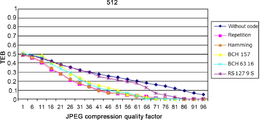
Figure 3.11. Comparison of the robustness of different codes against the JPEG attack
We note that from this quality level, all the codes have difficulties protecting the signature: the degradation is too strong and therefore the watermark channel is too noisy. Unsurprisingly, the absence of code is associated with the worst result. We can see that the codes intended to correct errors by erasure (error by blocking) are not suitable for this type of error or attack (RS code), unlike codes fighting against random errors.
The results will depend on the content of the image: the compression will adapt to this content and the errors will be greater when the images contain little information, for example textures, because the mark is the detail directly removed during the compression.
To illustrate this, we show the measurements for five different images with RS encoding. We apply a JPEG compression with a quality factor equal to 40. We can see Figure 3.12 that the results are very different depending on the content of the image. The frequential content of the image in Figure 3.13 is generally rich in high frequencies, while the image in Figure 3.14 is low in detail. We find that for the second image, it is more difficult to reconstruct the signature because of the content of the host image.
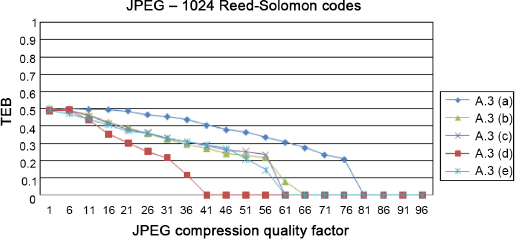
Figure 3.12. Comparison for different images of the Kodack database of robustness with an RQ encoding and an attack JPEG Quality = 40
This first simple experiment first of all shows the improvement, in terms of robustness, provided by the addition of a code. It also illustrates the importance of understanding and characterizing the attack in order to deduce therefrom the type of error that is associated, and therefore the most suitable correction code.
However, as we have seen, this result also depends on the element that we do not know at first glance, that is to say the content of the image.
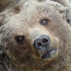
Figure 3.13. Image of a bear

Figure 3.14. Image of a plant
3.7.2. Additive Gaussian noise
We now propose the study of the attack by adding Gaussian white noise. In this case, the parameter is the noise level or, more precisely, the signal-to-noise level. Since by definition, the associated error is random, we see in Figure 3.15 that the codes designed for errors by area are again, not suitable. It is evident that the larger the image, the more efficient the external repetition coding and, therefore, the decoded signature displays little or no error in the end.
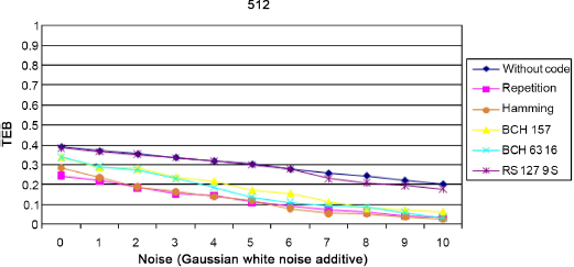
Figure 3.15. Comparison of the different encodings against an attack by adding Gaussian white noise
3.7.3. Saturation
Finally, we intend to study the impact of another type of attack: the modification of saturation. Saturation characterizes the colorful appearance of a pixel; in other words, the distance between the “color” pixel and the gray level axis. The modification of saturation will therefore involve bringing each pixel closer, or further from the gray axis. This is why the attack parameter takes both negative values (approximation of the gray axis) and positive values.
In order to fully understand the impact of this attack, we illustrate the result on the Lena image using an extreme setting, at –100 and +100. In the case of –100, the image becomes gray since each pixel is projected on the gray axis (Figure 3.16a). In the opposite direction, with a positive parameter at +100, there is an overflow phenomenon: the value of certain pixels comes out of the RGB cube, and therefore a phenomenon of “saturation” of the coordinates occurs on the different channels and they are suppressed to 255 (Figure 3.16b).

Figure 3.16. Effects of changes to saturation on the Lena image. a) Minimal change to saturation: –100, b) maximal change to saturation: 100
On reading the results of Figure 3.17, we see that the attack through weakening the saturation does not pose any problem, except when there is a projection on the gray axis, because in this case the image is no longer in color; however, the watermark used modifies the color vectors. We can see that when the saturation increases, above a factor of 30, apart from the RS code, the codes find it hard to reconstruct the signature. This is simply explained by the fact that the overflow phenomena will cause errors by area and therefore, this type of error will be better corrected by RS encoding.
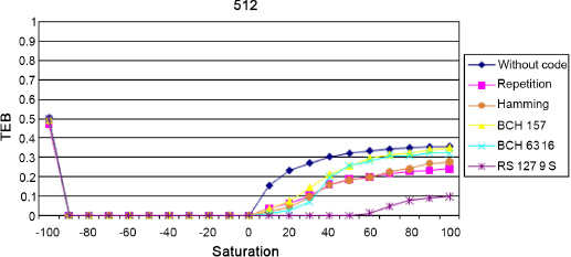
Figure 3.17. Comparison of coding processes faced with saturation for an image of size 512 × 512
In this section, we have seen that, faced with certain image modifications, the error produced can have a particular error structure. Taking the latter information into account, a suitable choice of correction codes makes it possible to optimize the detection performance. For example, when considering BCH and RS codes, BCH codes are more efficient than RS codes when the error is random. When the error has a per-packet structure, the RS codes are better. To continue this discussion between the right choice of code and the type of attack, we intend to introduce a particular code in section 3.8.
3.8. Using the rank metric
A useful tool for increasing the robustness of a mark is using error-correction codes. They make it possible to correct the errors produced by a given attack. Depending on the attack and the structure of the resulting errors, the type of code used is more or less effective.
Hamming distance-based codes have been around for over 40 years and have been the subject of many studies (MacWilliams and Sloane 1977) and applications in various fields, such as watermarking (Abdul et al. 2013). For some attacks, it happens that the errors are per packet, as we have seen. In this case, it is better to use more structured codes, that is, codes defined on a larger alphabet (e.g. GF(2m)), such as RS codes where it is possible to decode errors by packet. The errors are then no longer decoded independently on each bit, but on packets of m bits so that several errors in the same binary packet only count for a single error (a symbol error) in a code word.
In this section, we consider the use of a new metric called rank metric. These codes are already widely used in telecommunications for coding networks (Silva and Kschischang 2009) and in cryptography (Gabidulin et al. 1991; Gaborit et al. 2014). They are able to correct errors with a specific structure. Consider a code on GF(2m) of size m. Each coordinate of a code word on GF(2m) is encoded on m bits and since the length of the code is m, each code word can be seen as a matrix of size m × m.
As the metric used is the rank of a binary matrix, the decoding condition is shown with this metric; in other words, the code words received, whose errors have a low rank, can be corrected accurately. For example, an attack which reverses all the bits of a mark (in other words of a code word) cannot be corrected by a Hamming code. On the other hand, with rank metric codes, the error will be of rank 1 because the error is a matrix only made of binary symbols 1, and so, the code word that has been transmitted is found with ease.
We intend to introduce this type of correction in a watermarking process. Rank metric codes will first be defined, then a watermarking method combining the Lattice QIM method and the rank metric codes will be described. Thanks to a block decomposition of the image, we show how the proposed method can be resistant to image cropping.
3.8.1. Rank metric correcting codes
First, we propose to define and analyze rank metric codes.
3.8.1.1. Definitions and properties
Consider linear code ![]() of length n, defined in an alphabet
of length n, defined in an alphabet ![]() = GF(qm). The code words
= GF(qm). The code words ![]() are line vectors of the vector space GF(qm)n. Each component of the code word of
are line vectors of the vector space GF(qm)n. Each component of the code word of ![]() can be expressed as a vector belonging to GF(q)m. It is possible to write these components in the form of a column vector and therefore represent a code word by a matrix defined on GF(q)m×n.
can be expressed as a vector belonging to GF(q)m. It is possible to write these components in the form of a column vector and therefore represent a code word by a matrix defined on GF(q)m×n.
Considering a basis ![]() from GF(qm) over GF(q) and a code word x = (x1, ..., xn) ∈ GF(qm)n, we get a matrix representation of x, denoted as
from GF(qm) over GF(q) and a code word x = (x1, ..., xn) ∈ GF(qm)n, we get a matrix representation of x, denoted as ![]() , or X when there is no ambiguity defined, such that:
, or X when there is no ambiguity defined, such that:
as for everything 1 ≤ j ≤ n:
It is because of this matrix representation that it is possible to define a new metric on GF(qm)n by using the rank of a matrix.
3.8.1.2. Rank distance
Let x = (x1, . . . , xn) ∈ GF(qm)n. Rank x, denoted as wR(x), equals:
Let y = (y1, . . . , yn) ∈ GF(qm)n. The rank distance of x to y, denoted as dR(x, y), equals:
Of course, dR does have the properties of a distance. Compared to Hamming distance, we have the following property:
with x as a code word, and wh as the Hamming weight function.
We can also deduce that:
Briefly, this property is real because the number of linearly independent rows or columns (i.e. the rank) of a code word is always smaller than the number of different symbols in twos (Hamming weights). In other terms, since the rank of a vector is independent to the base used, the rank metric is less precise than the Hamming metric, because two vectors with the same weight can have the same rank.
3.8.1.3. Principle of rank metric codes
Delsarte was the first to study the rank metric (Delsarte 1978). Many properties of Hamming codes have adapted to rank metric codes. Linear code ![]() defined on a finite field GF(qm) can be seen as a subspace of GF(qm)n, but also as a metric space that has rank distance.
defined on a finite field GF(qm) can be seen as a subspace of GF(qm)n, but also as a metric space that has rank distance.
In addition, as ![]() is a linear code,
is a linear code, ![]() is a subspace of GF(qm)n. The linearity of a code is an interesting property since it makes it possible to manipulate code words more easily. As for Hamming codes, it is possible to define the minimal distance dmin from a rank metric code, such that:
is a subspace of GF(qm)n. The linearity of a code is an interesting property since it makes it possible to manipulate code words more easily. As for Hamming codes, it is possible to define the minimal distance dmin from a rank metric code, such that:
with the linearity property of the code, we have:
We note a linear rank metric code ![]() is of length n, dimension k and minimal distance d by its parameters [n, k, d]r or [n, k, (d − 1)/2]r or even [n, k]r, if it is not necessary to specify the minimum distance.
is of length n, dimension k and minimal distance d by its parameters [n, k, d]r or [n, k, (d − 1)/2]r or even [n, k]r, if it is not necessary to specify the minimum distance.
3.8.1.4. Decoding Gabidulin codes
The decoding bounds of rank metric codes (Singleton and Gilber–Varshanov bounds) are similar to those of Hamming codes. They are very useful for building decoding algorithms. Unlike classical Hamming codes, there is only a small number of families of codes for which a decoding algorithm is known.
Gabidulin codes are one of these families and have as parameters [n, k, n − k + 1]r on GF(qn), with n being the length of the code, k is the size of the code and d = n − k + 1 is the minimal distance (Gabidulin 1985). These codes are called Maximum Rank Distance (MRD), and so can correct up to (n − k)/2 errors. They can be seen as a rank metric family, similar to the famous RS codes (which are MDS). Since 1985, many decoding algorithms have been proposed (Gabidulin 1992; Loidreau 2006).
On closer inspection, the RS code decoding algorithm can be adapted for Gabidulin codes. By using a variant of the Welch–Berlekamp algorithm on linear polynomials, it is possible to obtain a quadratic complexity decoding.
3.8.1.5. Introduction to rank metric in a watermarking strategy
In practice, we use these codes in an extension GF(qm) of GF(2) and we can unite a binary vector of size m to each coordinate of a code word in such a way that code word c can be represented by a binary matrix of size m × m.
The integrated code word c is modified by an error e that can also be seen as a binary matrix of size m × m.
To assess the case in which the rank metric is more effective than the classical Hamming metric, we compare their behaviors by observing some examples of errors. Let y = c + e be a code word received after the extraction of a mark.
EXAMPLE.– m = 4 and a code word c:

with y such that:
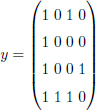
We have the following error:
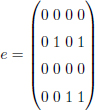
We observe that the error matrix e is of rank 2. If a rank metric code is able to correct up to 2 errors, then the word y is uniquely decoded in c. With a Hamming code of length 16, the error is of weight equal to 4. In this case, it is possible to find efficient codes with the two metrics for a reasonable dimension k.
Regardless of y and c, if we choose an error e such that:

the Hamming weight of e is 9, while the rank of e is 4: so it is impossible to find efficient codes with the two metrics.
If e is the identity matrix, the error is of full rank and only Hamming codes are useful.
From this example, we see that the rank metric codes become more interesting when the error has a particular structure. For example:
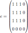
with the Hamming metric, we have nine errors in 16 transmitted bits and there is no code capable of decoding correctly, whereas with rank metric, e is only of rank 1. Therefore, we can easily decode such an error (e.g. with a Gabidulin code of parameters [4, 2, 3]).
In the same way that some attacks will be “linked” to RS or BCH codes, this type of error is found in the context of specific attacks. Rank metric codes will, in this case, be an alternative application to digital watermarking which is more efficient than classical Hamming codes.
We now propose a watermarking method integrating rank metric codes in order to protect against image cropping.
3.8.2. Code by rank metric: a robust watermarking method for image cropping
Image cropping erases an area of an image, which seriously damages the image. The information that has been inserted locally is therefore destroyed. One of the oldest contributions on image cropping was proposed by Swanson et al. (1996a, 1996b). Their method of watermarking uses a modulation algorithm of the bits of low weights on the DCT coefficients to insert their mark. Image cropping can also be associated with a similar attack called collage attack, which involves replacing an area of an image by another. This attack is also known as a variation of the image forgery attack, which is studied by Holliman and Memon (2000) in the context of the authentification of a digital image, studied by Fridrich and Goljan (2001). This type of attack is mainly studied in issues of image authentication or detection of modifications (malicious or not).
Later on, other works (Fridrich and Goljan 2001) proposed a mechanism for inserting an image into itself (or self-embedding) to withstand several attacks, such as falsification, cropping (or reframing) or even the replacement of areas in an image. The idea involves inserting a compressed version of a host image into itself using least significant bit modulation on DCT coefficients.
More recent works were published on the same subject (Aggarwal and Singla 2011; Khalid et al. 2013; Saneie and Naghsh 2016; Goli and Naghsh 2017). For example, an original approach is inspired by the mathematics of Sudoku (Felgenhauer and Jarvis 2006; Russell and Jarvis 2006). Their insertion strategy is based on the same principle as the self-embedding mechanism (reduction of the size of the host image to obtain a smaller mark), previously described to resolve the problem of image cropping and reframing. In the insertion stage, the host image is divided into N cells, identified by the integers from 1 to N (as in a sudoku grid). A new image is then generated with each cell replaced in a solution grid, the size of which is reduced, then inserted into a host image because of the modulation of the low-order bits on the DCT coefficients. However, these contributions only address problems of image authentication and detection of modifications by fragile watermarking methods. Compared to robust watermarking, the objectives are completely different.
The problem of image cropping can become more complex when the size of the attacked image is smaller than that of the marked image. At the detection stage, the mark must be synchronized before it can be extracted. One of the classic approaches against this problem was proposed by Kutter (1999). To insert a robust mark, this is repeated in several places of the image, as for the coding by repetition studied in this chapter.
To illustrate the possible contribution of codes, we intend to use the distinct features of the rank metric code to fight against this type of attack.
3.8.2.1. Description of the “rank metric method against cropping”
It seems rather difficult to design a method resistant to a cropping type attack. Basically, all contributions are based on the use of information repetition, that is, on the use of some form of information redundancy. Therefore, each locally inserted detail must depend on other details inserted in other regions of the image to detect the mark without error. The only solution to reconstruct the original message without error is to distribute the mark throughout the image. If an area is cropped and small enough, then the message can be extracted correctly. In the book, the approaches used are equivalent to using a repeating code.
We propose a different approach to deal with the image cropping problem using rank metric codes. To do this, a host image is broken down in n2 blocks with n as the length of a rank metric code (decomposition scheme illustrated in Figure 3.18). Each bit of the rank code word is then inserted into a block using L = 2 coefficients. We get an image that looks exactly like the matrix of a rank code word. Therefore, the distortions produced by the attacked image are reproduced directly on the error matrix e.
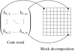
Figure 3.18. Insertion strategy using rank metric code and image block decomposition. Each bit bi,j is associated with a block
For example, a square-shaped area (of size l) is cropped. The blocks affected by this attack are directly transposed onto the error matrix e. Now consider a cropped row or column of width l. In the matrix e, a 1-bit line or a column appears. As we have seen previously, e has a specific error structure that is perfectly managed by rank metric codes. In fact, rk(e) = r′ with r′ is the number of blocks (in width) affected by the image cropping.
The two examples previously described produce errors of the same rank. In the second case, the distortion is maximized compared to the first case (cropped square) for errors of the same rank. In Figure 3.19, we show examples of attacked images, which all have a matrix error of the same rank.
Another interesting example of the rank metric is as follows: swapping two rows or columns of the same width does not change the rank of the error matrix if the coefficients chosen in each block have the same positions and the cut bands overlap the entire deconstruction of the image exactly. This swapping operation can be repeated indefinitely without changing the rank of the error. This case study is not considered in this chapter for lack of realism.
In section 3.8.2.2, we describe and analyze the robustness of the method proposed against image cropping.
3.8.2.2. Robustness of the rank metric against cropping
In our study, we distinguish between two types of cropping: the first type groups together images whose vertical or horizontal bands are entirely cut (Figure 3.20a) and the second type groups together images where only rectangular shapes are cut (Figure 3.20b). Also note that the cut bands do not necessarily overlap the block decomposition of the image. For errors of the same rank, the distortion is maximized with the first type compared to the second.
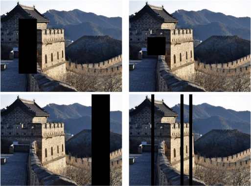
Figure 3.19. Cropped images with errors from the same rank
In our experimental measurements, we consider the first type of cropping for convenience and clarity. With the second type, the average rank of the error is exactly the same with a lower cropping percentage.
We measure distortions of images using the percentage of cropped image region denoted by cr. For the first type, we define cr such that:
where l is the number of pixels, in width, of the cut column and h is the height of the image.
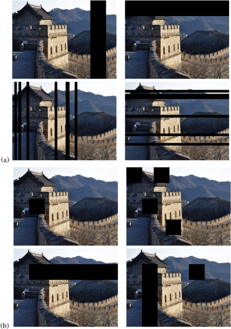
Figure 3.20. Types of image cropping. The top two rows (a) represent type 1 errors and the two bottom rows (b) represent type 2 errors
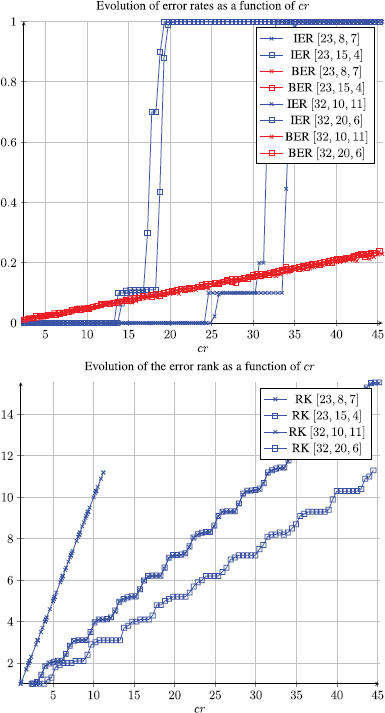
Figure 3.21. Average error rate and rank as a function of the cropping percentage cr
We have randomly chosen 1,000 images from the Corel image database whose size is 300 × 400 or 400 × 300 and calculated the respective averages of the BERs, the image error rates and error ranks. We have chosen different Gabidulin codes to assess the robustness of the proposed method against image cropping. In Figure 3.21, we see that the binary error rate and error rank curves are linearly increasing as cr increases for all values of n. When the average error rank (± 1.6) becomes greater than the maximum number of errors, we can see that the IER curves vary quickly from 0 to 1. Therefore, it becomes impossible to detect the original message. We then denote by crmax the highest percentage allowing an error-free detection.
This first observation shows, through experimentation, the applicability of rank metric codes in a digital watermarking strategy against image cropping. Of course, sometimes the detection performance is very poor. The main idea of the proposed method is to take advantage of the mathematical properties of the rank of a matrix. It is also possible to produce an example of a marked, and then cut image where detection is impossible (see Figure 3.22).
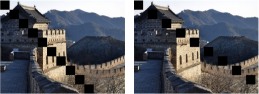
Figure 3.22. Examples of attacked images with the poorest detection performance. The error rank is large (≥ (n − k)/2) compared with the percentage of cropped area (cr′)
Discussing the parameters in more detail, when the encoding rate k/n decreases, the correction power t increases, which results in a higher value of crmax; in other words, the mark is more robust. Likewise, when n increases with fixed k, the encoding rate decreases and the correction power also increases, which also makes it possible to obtain a more robust mark.
However, the image quality should be carefully evaluated when inserting the mark because if n increases, it significantly degrades the host image. In fact, a greater value of n implies the quantization of n2 × L coefficients (the blocks are smaller).
Compared to BCH codes, rank metric codes are more efficient when we are faced with the first type of image cropping. We can see that the values of crmax reached by the rank metric codes correspond to higher BERs than the correction rates given by equivalent BCH codes. For example, with (n, k) = (23, 8) and crmax = 37%, we have a BER = 0.12 > t′/n′ = 0.09 (see Table 3.4 for other examples).
Table 3.4. Table of code correction parameters. For each row of the table, we have parameters of a rank metric code on the left and on the right are the parameters of an equivalent BCH code (t/n ≃ t′/n′)
| Gabidulin | BCH | |||
|---|---|---|---|---|
| [n, k, t] | crmax | BER to crmax | [n′, k′, t′] | t′/n′ |
| 16, 5, 5 | 41 % | 0,11 | 255, 87, 26 | 0,10 |
| 16, 8, 4 | 42 % | 0,1 | 255, 131, 18 | 0,07 |
| 16, 11, 2 | 41 % | 0,04 | 255, 171, 11 | 0,04 |
| 23, 8, 7 | 37 % | 0,12 | 511, 175, 46 | 0,09 |
| 23, 12, 5 | 36 % | 0,10 | 511, 250, 31 | 0,06 |
| 23, 15, 4 | 39 % | 0,07 | 511, 340, 20 | 0,04 |
| 32, 10, 11 | 35 % | 0,13 | 1023, 348, 87 | 0,09 |
| 32, 16, 8 | 35 % | 0,10 | 1023, 513, 57 | 0,06 |
| 32, 21, 5 | 35 % | 0,07 | 1023, 688, 36 | 0,04 |
However, rank metric codes are less effective than BCH codes when we are faced with the second type of image cropping. This is explained by the fact that the BER obtained at the value crmax is smaller than the correction rate t′/n′, associated with the equivalent BCH code. In addition, BCH codes can correct random errors and, therefore, are more robust against all types of image cropping if the BER is smaller than t′/n′. However, in this particular application, we can consider that the rank metric codes remain a better choice of correction codes, especially in the case where the Gabidulin codes are MRD. Even though BCH codes are the best for random errors, we are constrained by the choice of parameters. In fact, the length of a BCH code is an integer of the form n = 2m − 1.
Combined with the LQIM method and a block decomposition strategy in the spatial domain, we have shown that the proposed method can be robust to different types of image cropping by taking into account certain constraints. Additionally, these newly-introduced codes in digital watermarking make it possible to obtain better detection performance in certain cases (first type of image cropping). However, an important problem remains associated with this type of image modification: the synchronization of the mark when the size of the attacked image is different to that of the marked image. The aim of this section is to illustrate how a reflection on the nature of the error can lead to the use of more “specialized” codes.
3.9. Conclusion
In this chapter, in order to introduce the contribution of correction codes, we have chosen to explain the paradigm of robust watermarking, which aims to insert an invisible and robust mark to image modifications.
We then offered an introduction to correction codes by repetition, BCH and RS codes and recalled how they could be integrated very simply into robust watermarking. Through a simple example with a burying strategy by index modulation, we have shown how the use of codes improves robustness against attacks whose errors have a specific structure. We focused on the fact that the study of the error structure will guide us on the use of similar encoding. Simple experiments have illustrated this, which seems to be a line of thought that should probably be followed.
Finally, following this idea, we presented a type of error correction code, rarely in watermarking, using the rank metric instead of Hamming metric. Technically, Gabidulin codes were combined with the LQIM method to obtain a new type of resistance against specific attacks. For this, it was necessary to adapt the burying strategy (strategy of block decomposition of the image instead of inserting information at random positions). The image is then divided into blocks and each bit of a code word rank is associated with a block. This insertion strategy allows us to take advantage of the structure of the rank metric against different image cropping configurations. After studying the robustness of the proposed method with rank metric codes against this attack, we also showed that Gabidulin codes are more effective than BCH codes when the distortions are maximized for a fixed error rank. The last section showed how the design of the watermarking algorithm can, and should, take into account both the nature of the errors, the properties of the code and the burying process.
3.10. References
Abdul, W., Carré, P., Gaborit, P. (2013). Error correcting codes for robust color wavelet watermarking. EURASIP Journal on Information Security, 1, 1.
Aggarwal, A. and Singla, M. (2011). Robust watermarking of color images under noise and cropping attacks in spatial domain. Image, 6(9), 11.
Al-Askary, O. (2003). Iterative decoding of product codes. PhD Thesis, Royal Institute of Technology, Stockholm.
Al Maeeni, S., Kalbat, F., Al-Ahmad, H. (2015). Logo embedding in grayscale images using turbo product codes. Proceedings of the International Conference on Information and Communication Technology Research (ICTRC). IEEE, Abu Dhabi, 96–99.
Baldo, F., González, F.P., Scalise, S. (2001). Turbo coding for sample-level watermarking in the DCT domain. In Proceedings of the International Conference on Image Processing. IEEE, 1003–1006.
Barni, M., Bartolini, F., Furon, T. (2003). A general framework for robust watermarking security. Signal Processing, 83(10), 2069–2084.
Bas, P., Le Bihan, N., Chassery, J.-M. (2003). Color image watermarking using quaternion Fourier transform. Proceedings of the International Conference on Acoustics, Speech, and Signal Processing. IEEE, Hong Kong, III–521.
Baudry, S., Delaigle, J.-F., Sankur, B., Macq, B., Maitre, H. (2001). Analyses of error correction strategies for typical communication channels in watermarking. Signal Processing, 81(6), 1239–1250.
Berrou, C., Glavieux, A., Thitimajshima, P. (1993). Near Shannon limit errorcorrecting coding and decoding: Turbo-codes 1. Proceedings of the International Conference on Communications. IEEE, Geneva, 1064–1070.
Bose, R.C. and Ray-Chaudhuri, D.K. (1960). On a class of error correcting binary group codes. Information and Control, 3(1), 68–79.
Bravo-Solorio, S., Calderon, F., Li, C.-T., Nandi, A.K. (2018). Fast fragile watermark embedding and iterative mechanism with high self-restoration performance. Digital Signal Processing, 73, 83–92.
Burgett, S., Koch, E., Zhao, J. (1998). Copyright labeling of digitized image data. IEEE Communications Magazine, 36(3), 94–100.
Chan, C.-S. and Chang, C.-C. (2007). An efficient image authentication method based on Hamming code. Pattern Recognition, 40(2), 681–690.
Chan, P.-W. and Lyu, M.R. (2003). A DWT-based digital video watermarking scheme with error correcting code. Proceedings of the International Conference on Information and Communications Security. ICICS, Hohhot, 202–213.
Chan, P.W., Lyu, M.R., Chin, R.T. (2005). A novel scheme for hybrid digital video watermarking: approach, evaluation and experimentation. IEEE Transactions on Circuits and Systems for Video Technology, 15(12), 1638–1649.
Chang, C.-C., Chen, K.-N., Lee, C.-F., Liu, L.-J. (2011). A secure fragile watermarking scheme based on chaos-and-hamming code. Journal of Systems and Software, 84(9), 1462–1470.
Chemak, C., Lapayre, J.C., Bouhlel, M.S. (2007). A new scheme of image watermarking based on 5/3 wavelet decomposition and turbo-code. WSEAS Transactions on Biology and Biomedicine, 4(4), 45–52.
Chen, B. and Wornell, G.W. (1999a). Dither modulation: A new approach to digital watermarking and information embedding. Proceedings of SPIE: Security and Watermarking of Multimedia Contents, San Jose, 3657, 342–353.
Chen, B. and Wornell, G.W. (1999b). Quantization index modulation: A class of provably good methods for digital watermarking and information embedding. IEEE Transactions on Information Theory, 47(4), 1423–1443.
Cox, I.J., Doërr, G., Furon, T. (2006). Watermarking is not cryptography. In Digital Watermarking, Shi, Y.Q., Jeon, B. (eds). Springer, Berlin/Heidelberg.
Cvejic, N., Tujkovic, D., Seppanen, T. (2003). Increasing robustness of an audio watermark using turbo codes. Proceedings of the International Conference on Multimedia and Expo. IEEE, Baltimore, I–217.
Darbon, J., Sankur, B., Maitre, H. (2001). Error correcting code performance for watermark protection. SPIE Security and Watermarking of Multimedia Contents III, 4314, 663–673.
Delsarte, P. (1978). Bilinear forms over a finite field, with applications to coding theory. Journal of Combinatorial Theory, Series A, 25(3), 226–241.
Doërr, G., Rey, C., Dugelay, J.-L. (2005). Watermark resynchronization based on elastic graph matching. Proceedings of the International Conference: Sciences of Electronic, Technologies of Information and Telecommunications. SITET, Sousse.
Dugelay, J.-L., Roche, S., Rey, C., Doërr, G. (2006). Still-image watermarking robust to local geometric distortions. IEEE Transactions on Image Processing, 15(9), 2831–2842.
Eggers, J.J., Su, J., Girod, B. (2000a). A blind watermarking scheme based on structured codebooks. Proceedings of the IEE Seminar on Secure Images and Image Authentication. IEEE, London.
Eggers, J.J., Su, J.K., Girod, B. (2000b). Robustness of a blind image watermarking scheme. Proceedings of the International Conference on Image Processing. IEEE, Thessaloniki, 17–20.
Felgenhauer, B. and Jarvis, F. (2006). Mathematics of Sudoku I. Mathematical Spectrum, 39(1), 15–22.
Fridrich, J. and Goljan, M. (2001). Protection of digital images using self embedding. Proceedings of the Symposium on Content Security and Data Hiding in Digital Media. Newark, 1–6.
Gabidulin, E.M. (1985). Theory of codes with maximum rank distance. Problemy Peredachi Informatsii, 21(1), 3–16.
Gabidulin, E.M. (1992). A Fast Matrix Decoding Algorithm for Rank-Error-Correcting Codes. Springer, Berlin/Heidelberg.
Gabidulin, E.M., Paramonov, A., Tretjakov, O. (1991). Ideals over a non-commutative ring and their application in cryptology. Workshop on the Theory and Application of Cryptographic Techniques. EUROCRYPT, Brighton, 482–489.
Gaborit, P., Ruatta, O., Schrek, J., Zémor, G. (2014). New results for rank-based cryptography. Proceedings of the International Conference on Cryptology in Africa. AFRICACRYPT, Marrakech, 1–12.
Goli, M.S. and Naghsh, A. (2017). Introducing a new method robust against crop attack in digital image watermarking using two-step Sudoku. Proceedings of the International Conference on Pattern Recognition and Image Analysis (IPRIA). IEEE, Faro, 237–242.
Guruswami, V. and Sudan, M. (1998). Improved decoding of reed-solomon and algebraic-geometric codes. Proceedings of the 39th Annual Symposium on Foundations of Computer Science. IEEE, Palo Alto.
Hamming, R.W. (1950). Error detecting and error correcting codes. Bell Labs Technical Journal, 29(2), 147–160.
He, D., Sun, Q., Tian, Q. (2003). A semi-fragile object based video authentication system. Proceedings of the 2003 International Symposium on Circuits and Systems. IEEE, Bangkok, III–III.
Hernandez, J.R., Delaigle, J.-F., Macq, B.M. (2000). Improving data hiding by using convolutional codes and soft-decision decoding. Proceedings of SPIE: Security and Watermarking of Multimedia Contents II, 3971, 24–48.
Ho, C.K. and Li, C.-T. (2004). Semi-fragile watermarking scheme for authentication of jpeg images. Proceedings of the International Conference on Information Technology: Coding and Computing. IEEE, Las Vegas, 7–11.
Holliman, M. and Memon, N. (2000). Counterfeiting attacks on oblivious blockwise independent invisible watermarking schemes. IEEE Transactions on Image Processing, 9(3), 432–441.
Hsieh, C.-T. and Wu, Y.-K. (2001). Digital image multiresolution watermark based on human visual system using error correcting code. Journal of Applied Science and Engineering, 4(3), 201–209.
Justesen, J. and Høholdt, T. (2004). A Course in Error-correcting Codes, Volume 1. European Mathematical Society, Helsinki.
Kesal, M., Mihcak, M.K., Koetter, R., Moulin, P. (2000). Iteratively decodable codes for watermarking applications. Proceedings of the 2nd International Symposium on Turbo Codes and Related Topics. ISTC, Brest.
Khalid, S.K.A., Deris, M.M., Mohamad, K.M. (2013). Anti-cropping digital image watermarking using Sudoku. International Journal of Grid and Utility Computing, 4(2–3), 169–177.
Khan, A., Siddiqa, A., Munib, S., Malik, S.A. (2014). A recent survey of reversible watermarking techniques, Information Sciences, 279, 251–272.
Kschischang, F.R., Frey, B.J., Loeliger, H.A. (2001). Factor graphs and the sum-product algorithm. IEEE Transactions on Information Theory, 47(2), 498–519.
Kutter, M. (1999). Watermarking resistance to translation, rotation, and scaling. Proceedings of SPIE: Multimedia Systems Applications, 3528, 423–432.
Lades, M., Vorbruggen, J.C., Buhmann, J., Lange, J., von der Malsburg, C., Wurtz, R.P., Konen, W. (1993). Distortion invariant object recognition in the dynamic link architecture. IEEE Transactions on Computers, (3), 300–311.
Lancini, R., Mapelli, F., Tubaro, S. (2002). A robust video watermarking technique in the spatial domain. Proceedings of the International Symposium on VIPromCom Video/Image Processing and Multimedia Communications. IEEE, Zadar, 251–256.
Lee, J. and Won, C.S. (2000). A watermarking sequence using parities of error control coding for image authentication and correction. IEEE Transactions on Consumer Electronics, 46(2), 313–317.
Lefèvre, P., Carré, P., Gaborit, P. (2018). Watermarking and rank metric codes. Proceedings of the 2018 International Conference on Acoustics, Speech and Signal Processing (ICASSP2018). IIEEE, Calgary.
Lefèvre, P., Carré, P., Gaborit, P. (2019). Application of rank metric codes in digital image watermarking. Signal Processing: Image Communication, 74, 119–128.
Li, Q. and Cox, I.J. (2007). Improved spread transform dither modulation using a perceptual model: Robustness to amplitude scaling and JPEG compression. Proceedings of the International Conference on Acoustics, Speech and Signal Processing. IEEE, Honolulu, II–185.
Liu, S.-C. and Lin, S.D. (2006). BCH code-based robust audio watermarking in the cepstrum domain. Journal of Information Science and Engineering, 22(3), 535–543.
Loidreau, P. (2006). A Welch–Berlekamp Like Algorithm for Decoding Gabidulin Codes. Springer, Berlin/Heidelberg.
Lu, H., Shen, R., Chung, F.-L. (2003). Fragile watermarking scheme for image authentication. Electronics Letters, 39(12), 898–900.
MacWilliams, F.J. and Sloane, N.J.A. (1977). The Theory of Error-correcting Codes. Elsevier, Amsterdam.
Maeno, K., Sun, Q., Chang, S.-F., Suto, M. (2006). New semi-fragile image authentication watermarking techniques using random bias and nonuniform quantization. IEEE Transactions on Multimedia, 8(1), 32–45.
Moulin, P. and Koetter, R. (2005). Data-hiding codes. Proceedings of the IEEE, 93(12), 2083–2126.
Oostveen, J.C., Kalker, T., Staring, M. (2004). Adaptive quantization watermarking. Proceedings of SPIE: Security, Steganography, and Watermarking of Multimedia Contents VI, 5306, 296–304.
Pérez-González, F., Mosquera, C., Barni, M., Abrardo, A. (2005). Rational dither modulation: A high-rate data-hiding method invariant to gain attacks. IEEE Transactions on Signal Processing, 53(10), 3960–3975.
Reed, I.S. and Solomon, G. (1960). Polynomial codes over certain finite fields. Journal of the Society for Industrial and Applied Mathematics, 8(2), 300–304.
Rey, C., Amis, K., Dugelay, J.-L., Pyndiah, R., Picart, A. (2003). Enhanced robustness in image watermarking using turbo codes. Proceedings of SPIE: Security and Watermarking of Multimedia Contents V, 5020, 330–337.
Russell, E. and Jarvis, F. (2006). Mathematics of Sudoku II. Mathematical Spectrum, 39(2), 54–58.
Saneie, S.H. and Naghsh, A. (2016). Introducing a new method of robust digital image watermarking against cropping and salt and pepper noise using sudoku. Majlesi Journal of Multimedia Processing, 4(4), 1–4.
Schaathun, H.G. (2008). On error-correcting fingerprinting codes for use with watermarking. Multimedia Systems, 13(5–6), 331–344.
Shehab, A., Elhoseny, M., Muhammad, K., Sangaiah, A.K., Yang, P., Huang, H., Hou, G. (2018). Secure and robust fragile watermarking scheme for medical images. IEEE Access, 6, 10269–10278.
Silva, D. and Kschischang, F.R. (2009). On metrics for error correction in network coding. IEEE Transactions on Information Theory, 55(12), 5479–5490.
Sudan, M. (1997). Decoding of Reed Solomon codes beyond the error-correction bound. Journal of Complexity, 13(1), 180–193.
Sun, Q. and Chang, S.-F. (2002). Semi-fragile image authentication using generic wavelet domain features and ECC. Proceedings of the International Conference on Image Processing. IEEE, Rochester, II–II.
Swanson, M.D., Zhu, B., Tewfik, A.H. (1996a). Robust data hiding for images. Proceedings of the Digital Signal Processing Workshop. IEEE, Loen, 37–40.
Swanson, M.D., Zhu, B., Tewfik, A.H. (1996b). Transparent robust image watermarking. Proceedings of the International Conference on Image Processing. IEEE, Lausanne, 211–214.
Verma, B., Jain, S., Agarwal, D.P., Phadikar, A. (2006). A new color image watermarking scheme. INFOCOMP, 5(3), 37–42.
Viterbi, A. (1967). Error bounds for convolutional codes and an asymptotically optimum decoding algorithm. IEEE Transactions on Information Theory, 13(2), 260–269.
Wang, S.-H. and Lin, Y.-P. (2004). Wavelet tree quantization for copyright protection watermarking. IEEE Transactions on Image Processing, 13(2), 154–165.
Wolfgang, R.B. and Delp, E.J. (1999). Fragile watermarking using the VW2D watermark. Security and Watermarking of Multimedia Contents, 3657, 204–214.
Wong, P.W. and Memon, N.D. (2000). Secret and public key authentication watermarking schemes that resist vector quantization attack. Proceedings of SPIE: Security and Watermarking of Multimedia Contents II, 3971, 417–428.
Yeung, M.M. and Mintzer, F. (1997). An invisible watermarking technique for image verification. Proceedings of the International Conference on Image Processing. IEEE, Santa Barbara, 680–683.
Zamir, R. and Feder, M. (1994). On lattice quantization noise. Proceedings of the Data Compression Conference. IEEE, Snowbird, 380–389.
Zhang, F., Zhang, X., Chen, Z. (2005). Digital image authentication based on error-correction codes. Proceedings of the International Conference on Computational and Information Science. ICCS, Atlanta, 433–438.
Zhou, X., Duan, X., Wang, D. (2004). A semifragile watermark scheme for image authentication. Proceedings of the 10th International Multimedia Modelling Conference. IEEE, Brisbane, 374–377.
Zinger, S., Jin, Z., Maitre, H., Sankur, B. (2001). Optimization of watermarking performances using error correcting codes and repetition. In Communications and Multimedia Security Issues of the New Century, Steinmetz, R., Dittman, J., Steinebach, M. (eds). Springer, Boston.
- For a color version of all figures in this chapter, see www.iste.co.uk/puech/multimedia1.zip.