Chapter 6

Technological Hazard Characterization

V. Cozzani
E. Salzano    Department of Civil, Chemical, Environmental, and Materials Engineering, University of Bologna, Bologna, Italy

Abstract

In the framework of Natech risk assessment, technological hazard refers to a potential for the occurrence of adverse effects due to the release of hazardous substances, from process or storage equipment, caused by natural-hazard impacts. It is important to identify the equipment that acts as a hazard source, and to rank the hazard in terms of the type and amount of hazardous substances it contains, its operating conditions, as well as its vulnerability with respect to natural hazards. This chapter examines these aspects to support the prioritization of specific measures for Natech accident prevention and mitigation, and to focus the application of detailed quantitative risk-analysis techniques to a limited set of accident scenarios or equipment items that are considered to be the most critical.

Keywords

technological hazard
substance hazard
toxicity
flammability
equipment vulnerability
hazard ranking
In the framework of Natech risk assessment, technological hazard refers to a potential for the occurrence of adverse effects due to the release of hazardous substances, from process or storage equipment, caused by natural-hazard impacts. It is important to identify the equipment that acts as a hazard source, and to rank the hazard in terms of the type and amount of hazardous substances it contains, its operating conditions, as well as its vulnerability with respect to natural hazards. This chapter examines these aspects to support the prioritization of specific measures for Natech accident prevention and mitigation, and to focus the application of detailed quantitative risk-analysis techniques to a limited set of accident scenarios or equipment items that are considered to be the most critical.

6.1. Introduction

The United Nations Office for Disaster Risk Reduction defines a technological hazard as (UNISDR, 2015):

A hazard originating from technological or industrial conditions, including accidents, dangerous procedures, infrastructure failures or specific human activities, that may cause loss of life, injury, illness or other health impacts, property damage, loss of livelihoods and services, social and economic disruption, or environmental damage.

The comment to this definition explicitly mentions the Natech hazards that originate from the impacts of natural events on hazardous industrial installations, such as nuclear power plants, or chemical processing, and storage facilities. As was already discussed in the previous chapters, the release of hazardous substances due to process upsets or structural failure triggered by natural hazards can affect plant workers, the population, property, and the environment both in- and outside the area impacted by the natural event.
In the framework of Natech risk assessment, the evaluation of technological hazards serves the purpose of identifying the potential sources of adverse effects involving the release of hazardous substances, following the impact of one or multiple natural events. This starts with the assessment of the hazard that an equipment item containing a hazardous substance poses, regardless of the accident trigger. However, when dealing with natural hazards, several limitations present themselves. In particular, the structural capacity, i.e., the absolute strength of the system beyond the expected or design loads or, in other words, the structural vulnerability of the system with respect to natural events is crucial and needs to be considered in Natech risk assessment.
With respect to Natech risk, the potential technological hazard sources should be prioritized by ranking process and storage equipment on the basis of three main factors:
1. The hazard of the substance or mixture of substances and the amount of the substance or mixture of substances (stored, produced, or transported) present in the unit or equipment item considered.
2. The physical state of the substance contained in the equipment.
3. The structural vulnerability of the vessel (equipment item) with respect to the natural event.
These three factors will be discussed in the following sections with specific reference to natural-hazard impacts.

6.2. Substance Hazard
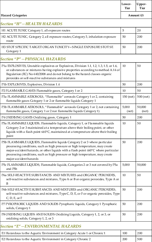
The hazard associated with a substance is strictly related to the intrinsic capacity of the substance, or mixture of substances, to produce harm to people, property, and the environment. This hazard is clearly general and is not specific to Natech risks. Hence, the substance information in the European REACH Regulation (European Union, 2006), which regulates the registration, evaluation, authorization, and restriction of chemicals in the European Union, can be used for the evaluation of the technological hazard.
This information can be combined with hazard categories from the European Regulation on classification, labeling, and packaging (CLP) of substances and mixtures (ECHA, 2015European Union, 2008), and substance data and related threshold quantities in the Seveso Directive on the control of major-accident hazards involving dangerous substances (European Union, 1997) and its amendments (European Union, 2003 2012). The Seveso Directive also includes a list of particularly problematic substances that are named explicitly and for which separate qualifying quantities apply. Table 6.1 shows the list of dangerous-substance categories and associated thresholds for lower- and upper-tier Seveso establishments as per the Seveso Directive. Further details can be found in the cited Directives and Regulations. Eventually, the substances to be considered in the hazard assessment are only those that are stored or processed in sufficient amounts to produce damage.

Table 6.1

List of Substance-Hazard Categories According to the CLP Regulation and Threshold Amounts for Lower- and Upper-Tier Installations as per the Seveso Directive (European Union, 2008 2012)

Hazard Categories Lower-Tier Upper-Tier
Amount (t)

Section “H”—HEALTH HAZARDS

H1 ACUTE TOXIC Category 1, all exposure routes 5 20
H2 ACUTE TOXIC, Category 2, all exposure routes; Category 3, inhalation exposure route 50 200
H3 STOT SPECIFIC TARGET ORGAN TOXICITY—SINGLE EXPOSURE STOT SE Category 1 50 200

Section “P”—PHYSICAL HAZARDS

P1a EXPLOSIVES, Unstable explosives or Explosives, Division 1.1, 1.2, 1.3, 1.5, or 1.6, or substances or mixtures having explosive properties according to method A.14 of Regulation (EC) No 440/2008 and do not belong to the hazard classes organic peroxides or self-reactive substances and mixtures 10 50
P1b EXPLOSIVES, Explosives, Division 1.4 50 200
P2 FLAMMABLE GASES Flammable gases, Category 1 or 2 10 50
P3a FLAMMABLE AEROSOLS, “Flammable” aerosols Category 1 or 2, containing flammable gases Category 1 or 2 or flammable liquids Category 1 150 (net) 500 (net)
P3b FLAMMABLE AEROSOLS, “Flammable” aerosols Category 1 or 2, not containing flammable gases, Category 1 or 2 nor flammable liquids Category 1) 5,000 (net) 50,000 (net)
P4 OXIDISING GASES Oxidizing gases, Category 1 50 200
P5a FLAMMABLE LIQUIDS, Flammable liquids, Category 1, or Flammable liquids Category 2 or 3 maintained at a temperature above their boiling point, or other liquids with a flash point ≤60°C, maintained at a temperature above their boiling point 10 50
P5b FLAMMABLE LIQUIDS, Flammable liquids Category 2 or 3 where particular processing conditions, such as high pressure or high temperature, may create major-accident hazards, or other liquids with a flash point ≤60°C where particular processing conditions, such as high pressure or high temperature, may create major-accident hazards 50 200
P5c FLAMMABLE LIQUIDS, Flammable liquids, Categories 2 or 3 not covered by P5a and P5b 5,000 50,000
P6a SELF-REACTIVE SUBSTANCES AND MIXTURES and ORGANIC PEROXIDES, self-reactive substances and mixtures, Type A or B or organic peroxides, Type A or B 10 50
P6b SELF-REACTIVE SUBSTANCES AND MIXTURES and ORGANIC PEROXIDES, self-reactive substances and mixtures, Type C, D, E, or F or organic peroxides, Type C, D, E, or F 50 200
P7 PYROPHORIC LIQUIDS AND SOLIDS Pyrophoric liquids, Category 1 Pyrophoric solids, Category 1 50 200
P8 OXIDISING LIQUIDS AND SOLIDS Oxidizing Liquids, Category 1, 2, or 3, or oxidizing solids, Category 1, 2, or 3 50 200

Section “E”—ENVIRONMENTAL HAZARDS

E1 Hazardous to the Aquatic Environment in Category Acute 1 or Chronic 1 100 200
E2 Hazardous to the Aquatic Environment in Category Chronic 2 200 500

Section “O”—OTHER HAZARDS

O1 Substances or mixtures with hazard statement EUH014 100 500
O2 Substances and mixtures which in contact with water emit flammable gases, Category 1 100 500
O3 Substances or mixtures with hazard statement EUH029 50 200


Analyses of past Natech accidents showed that for Natech risk assessment special attention needs to be paid to atypical scenarios caused by the interaction between the substance hazard and the specific features of the natural event causing the loss of containment. In particular, accident scenarios involving the release of hazardous substances into water are quite frequent for some Natech events (floods, heavy rain, tsunami, etc.). In this context, hazards related to water contamination but also to substance reactivity with water may play an important role in influencing and possibly aggravating the risks due to the technological hazard (cf. Chapter 3).

6.3. Physical State of the Released Substance

The physical state of the release plays an important role in establishing the hazard due to Natech events. Several physical states are of relevance in determining the substance hazard: liquefied gases under pressure, cryogenic liquefied gases, compressed gases, liquids, and solids.
Liquefied gases under pressure are fluids that are in the liquid phase at a temperature that is higher than their boiling point at atmospheric pressure. Two different options exist: (1) liquefied gases under pressure at ambient temperature (i.e., fluids that at ambient temperature and atmospheric pressure would be in the gas phase), and (2) fluids in the liquid phase at a temperature higher than ambient temperature and higher than their boiling point at atmospheric pressure.
Option (1) is a widely used storage strategy for many categories of chemicals and fuel, such as liquefied petroleum gas (LPG), chlorine, and ammonia. Option (2) is usually applied in certain processing activities of the chemical industry. Equipment containing liquids under pressure at high temperature is specific to process operations and not of bulk storage, it is less frequently used and has a lower inventory. Nevertheless, for both options, any failure of the equipment that contains hazardous materials may result in a rapid or almost instantaneous release of the substance to the atmosphere, thus producing severe accident scenarios due to the simultaneous release of vapor, a liquid aerosol, and, depending on the release conditions, the formation of a pool of boiling liquid.
If gas is liquefied by cooling the fluid below ambient temperature, a cryogenic liquid is obtained. Cryogenic liquids are liquefied gases that are kept in their liquid state at very low temperatures (usually at their boiling point at atmospheric pressure). All cryogenic liquids are gases at ambient temperature and atmospheric pressure. The most important example of this type of substance is liquefied natural gas (LNG). The main technological hazard is related to loss of containment of the substance. If a cryogenic liquid is released to the environment, a sudden vaporization takes place until a pool of boiling liquid is formed. A vapor cloud originates from the initial vaporization and from the boiling pool. However, the energy needed for the vaporization is supplied from the environment (ground or air). This usually decreases the rate of evaporation, thus affecting the dispersion mode. However, when marine structures are of concern (as for LNG, e.g., LNG terminals or jetties) the rapid heat exchange with the sea or river/lake water may affect the evaporation and trigger anomalous accidents (Bubbico and Salzano, 2009).
Compressed gas releases will immediately generate a gas cloud. However, due to the limited inventory of storage systems, caused by the low density of compressed gases, the actual relevance and overall severity of such releases needs to be specifically assessed.
When liquids are released, hazards are created due to the entrainment of vapors in the air that comes in contact with the liquid. Liquid evaporation takes place, and a cloud of vapors may be formed. Nevertheless, the intensity of evaporation and the concentration of vapors in the cloud are expected to be much lower than for liquefied gases, due to the difference in driving force available for evaporation.
The hazard related to substances in the solid state is essentially associated with the chemical properties of the substance. However, dust explosions and fires are mainly linked with the physical characteristics. Hence, a “fine dust” physical state should be considered.
The detailed analysis of release scenarios is out of the scope of this chapter. The reader is referred to comprehensive publications on the topic to obtain more detailed information on the qualitative and quantitative characterization of events involving the loss of containment of chemical substances in different physical states (Mannan, 2005van Den Bosch and Weterings, 2005).
In the case of Natech scenarios, the possibility that liquid pools or released solid substances come in contact with and are displaced by water needs to be taken into account in the risk analysis. This may cause specific accident scenarios that are usually disregarded when loss of containment takes place due to internal failures of the system.

6.4. Equipment Vulnerability

The vulnerability of an equipment item in a Natech event derives from its structural features. As such, its vulnerability can be obtained from detailed structural modeling only. Nevertheless, in the framework of quantitative risk analysis, the introduction of a simplified approach to the assessment of equipment vulnerability with respect to natural-hazard loading is useful. Ranking methodologies of process units are thus needed to help prioritize intervention, design prevention and mitigation systems and measures, be they technical or organizational, and restrict the application of detailed analysis techniques (QRA) to a limited number of critical equipment items.
On the path to defining a ranking procedure and the propensity to cause an accident in a given technological system, it is worth considering that any process which converts raw materials or intermediate products to final products, or any transportation system of fluids, should first be ranked by virtue of the specific hazard of the substance involved. Simply put, a large storage tank containing water cannot be considered as hazardous as a similar tank containing flammable materials, whatever its scale or construction characteristics. Besides, for the given substance, several possible equipment types might exist, each of which with different structural characteristics, functions, and scale.
Various approaches for classifying equipment using different categories are available. Based on several past analyses, equipment was categorized in three classes with respect to the design standard: (1) atmospheric equipment (storage tank and process units), (2) pressurized equipment (cylindrical buried, cylindrical above-ground, spheres), and (3) pipeline systems. The following sections will be devoted to these three types of equipment only.

6.4.1. Atmospheric Equipment

Atmospheric equipment includes storage tanks and process units adopted for a range of applications, such as distillation, separation, extraction, etc. Due to their capacity and wide diffusion, atmospheric storage tanks are the most relevant type of equipment. They are constructed worldwide following the American Petroleum Institute standard API 650 (American Petroleum Institute, 2007) and are typically vertical cylinders. Other atmospheric process equipment, such as distillation towers, or cyclones, are also designed to similar codes and standards, they have, however, slender geometry.
From a structural point of view, all these equipment types are generally built by using carbon steel or stainless steel, with a typical maximum allowable working pressure (MAWP) and corresponding failure pressure of few millibars. Shell thicknesses range from 5 mm to about 1 cm for some sections of jumbo tanks. Interestingly, studies have shown that earthquake-triggered structural damage involving water tanks is very similar to tanks containing hazardous materials and their behavior can be described using a similar methodology. Distillation and absorption columns, and similar tower units typically have an internal diameter greater than 0.1 m.

6.4.2. Pressurized Equipment

Pressurized equipment is often used for very hazardous substances and is typically cylindrical (buried or above-ground) or spherical. Their design and certification is governed worldwide by well-known design codes, such as the ASME Boiler and Pressure Vessel Code (ASME, 2015) in North America, and the EU Directive 2009/105/EC (European Union, 2009).
The most common hazardous system in the process industry is related to the storage of large amounts of liquefied gases, such as LPG (propane, butane, and their mixture), ethylene, or hydrogen. The shell thickness and the corresponding design pressure is clearly larger than for atmospheric equipment and may reach several centimeters for small equipment like chemical reactors. Pressure vessels are typically welded, and are not intended to be fired and subjected to an internal gauge pressure greater than 0.5 bars. The MAWP is generally lower than 30 bar, and the minimum and maximum working temperatures are, respectively, −50 and 300°C for steel or 100°C for aluminum or aluminum alloy vessels.
When large amounts of hazardous materials are stored in pressurized equipment, the vessels are often mounded or buried, to avoid any interaction with external effects in case of fire, explosion, or simple collisions with objects. In this case, several accident scenarios can be considered as not credible (and the technological hazard is therefore reduced to negligible values) due to the physical impossibility of accidents. Nevertheless, this kind of equipment may have been designed with external auxiliary systems and pipes, which should also be considered as a source of technological hazard.
Pressurized equipment typically also includes shell and tube heat exchangers, seal-less pumps with a specified maximum flow-rate greater than 0.5 m3/h, or reactors, and some elongated vessels (distillation).

6.4.3. Pipelines

Pipeline systems within industrial installations may be above-ground or buried. The pipe body can be continuous or segmented and is typically built from carbon or stainless steel when transporting hazardous substances.
For the evaluation of the technological hazard, the pipeline system has to be separated into transportation and distribution networks. The transportation network is generally used to transfer the liquid or gas from the production place to the industrial plants or urban distribution system.
With respect to gas, overland transportation pipelines generally operate at high pressure (>70 bars), in order to transfer a large amount of fluid per unit time. In the United States, for example, the large-scale natural-gas transmission system includes around 300,000 km of high-strength, steel pipelines, with diameters between 0.6 and 0.9 m and pressures between 34 and 97 bars. With respect to the seismic vulnerability of pipeline systems, two large categories based on pipe diameter exist: (1) D ≥ 400 mm for high-pressure transmission systems; and (2) D < 400 mm for distribution and low-pressure transmission systems (Lanzano et al., 2013).
For distribution systems the most common pipe materials are cast iron, ductile iron, steel, and polymers. Cast iron was largely used in the last century. This material shows high fragility and lacks ductility, which raises safety concerns. For these reasons, pipelines are nowadays made of ductile iron, steel, and plastic materials like polyvinylchloride, polyethylene (HDPE), and glass-reinforced fiber polymers. Other construction materials, such as concrete, are used for water and wastewater pipelines.
The damage patterns occurring in these structures are largely dependent on the material base properties and the joint detailing. For this reason, all the possible combinations of material and joints are typically divided into two categories: (1) continuous pipelines (CP) and (2) segmented pipelines (SP), or equivalently in brittle (SP) and ductile (CP) in terms of prefailure deformations.
Table 6.2 shows the main structural features, which are essential for gas and liquid pipelines. It is worth noting that hazardous materials (toxic, flammable) must be transported only in continuous pipelines, which have high strength and can tolerate large deformations before breaking and subsequent fluid release.

Table 6.2

Structural Features of Pipelines (Lanzano et al., 2014)

Pipelines Materials Joints Damage Patterns
Continuous (CP) Steel; polyethylene; polyvinylchloride; glass fiber reinforced polymer Butt welded; welded slip; chemical weld; mechanical joints; special joints Tension cracks; local buckling; beam buckling
Segmented (SP) Asbestos cement; reinforced concrete; polyvinylchloride (PVC); vitrified clay; cast iron Caulked joints; bell end spigot joints Axial pull-out; crushing of bell end; crushing of spigot joints; circumferential failure; flexural failure

The choice of the joints is also a crucial issue in the seismic design of pipelines, particularly for those used for gas. In order to avoid that the pipeline joints perform as weak points, they must be designed aiming at restoring the continuity of the pipeline body in terms of strength and stiffness. This is achieved by mostly using welded joints, however, in some cases, mechanical and special joints are also used.
Among the different welding techniques, three are remarkable for steel pipelines: (1) oxyacetylene welding (OAW), (2) submerged arc welding (SAW), and (3) high-quality welding. In the past, the preferred welding type belonged to the first and second categories. In fact, the SAW gives a good strength recovery compared to OAW, which suffered extensive damage in earthquakes.
An important distinguishing factor for the hazard from pipeline systems is whether the pipeline is installed above or below ground (Lanzano et al., 2014). Generally, the burial depth of gas pipelines is in the range of 1–2 m. Pipelines with very large diameters might be buried deeper. For the above-ground case, the use of support structures is common. Gas pipes are frequently placed below ground level. The burying process is beneficial for two reasons. On the one hand, the surrounding soil protects the pipeline from above-ground hazards, such as natural events or accidents. Secondly, the lateral confinement provided by the soil, which increases with depth, reduces the likelihood of domino effects due to fire or explosion.
A simple measurement for pipeline performance and the associated technological hazard is the pipeline repair rate, RR (ALA, 2001).

6.4.4. Hazard Classification Based on Structural Features and Hazard of the Secondary Scenario

The analysis of the expected damage and the criticality of the associated accident scenarios can provide further indications on whether equipment is critical. In the framework of Natech risk analysis, the structural damage itself may have only a limited relevance. The severity of the accident following equipment damage and loss of containment is the element that should take priority in the analysis.
A first classification of equipment criticality may be derived from Table 6.3 for units containing substances with the hazard characteristics and nonnegligible substance amounts as shown in Table 6.1. Substance characteristics were combined with the expected structural vulnerability of the equipment and the relevance of the hazard related to its physical state.

Table 6.3

Technology Hazard Matrix With 1 = Low Hazard and 5 = High Hazard

Equipment Liquefied Gas Compressed Gas Cryogenic Liquid Liquid Fine Dusts
Pressurized (above-ground) 5 4 4 2 1
Pressurized (underground) 2 3 2 2 1
Atmospheric 5 3 3
Pipeline (above-ground) 4 3 4 2 1
Pipeline (underground) 3 2 3 1

Underground equipment is considered buried or mounded.

The highest hazard is assumed for above-ground, pressurized equipment that contains liquefied gases. Any structural failure or loss of control of the associated industrial process, either related to anthropogenic causes or natural events, may result in a large-scale accident due to the rapid release of content and the possible escalation to fire, explosion, toxic dispersion, or even to environmental disaster. The score is higher than for nonliquefied gases because of the large difference in density, and hence mass per volume. A similar reasoning can be used to explain the high hazard score for above-ground pipelines, which contain, however, lower amounts of hazardous substances. Cryogenic liquids contained in atmospheric vessels also result in the maximum hazard score due to the vessels’ intrinsic fragility in case of internal pressurization.
When buried or mounded, both liquefied and cryogenic liquids are less hazardous due to the intrinsic protection afforded by the mound or surrounding soil. Compressed gas may be slightly more hazardous if released through thin layers of soil or structures.
Where liquid substances are a concern, the hazard is related to their flammability and toxicity, and also to environmental issues. Atmospheric equipment is typically utilized for high-capacity storage of hazardous liquids, and this leads in turn to higher hazards. Although having a lower hazard score for liquids, pressurized equipment is typically used for very hazardous materials. Consequently, the failure and following loss of containment can also result in nonnegligible hazards.
Finally, the highest hazard score for fine dusts is associated with large-scale atmospheric equipment, such as silos or mills. In this case, fire or explosions may be induced by external causes which can result in severe accident scenarios.
A more detailed evaluation of the technological hazard should, however, also take into account the intensity of the loss of containment following equipment damage and the specific hazard of the material released. A useful approach to assess escalation thresholds is the description of secondary target damage by a discrete number of structural Damage States (DSs) and of Loss Intensities (LIs) following the scheme originally introduced to obtain a cost estimate of damage caused by explosions (Tam and Corr, 2000) or by natural events (HAZUS, 1997). The structural DS of equipment may, for instance, be described by two classes: DS1, equivalent to minor damage to the structure or to auxiliary equipment, and DS2, with intense damage or even total collapse of the structure.
The shift to DSs due to natural-hazard impact may also be associated to a loss of containment, whose intensity is among the most important factors affecting the relevance of the Natech scenario. In fact, increasing LIs usually result in an increase of the severity of the loss-of-containment scenario and in a decrease of the time available for successful mitigation. The LIs following vessel damage may then be represented by a discrete number of LI categories or so-called risk states RS. Following the approach used in the Purple Book (Uijt de Haag and Ale, 1999), three LI categories were defined: (1) LI1: “minor loss,” defined as the partial loss of inventory, or the total loss of inventory in a time interval higher than 10 min from the impact of the blast wave; (2) LI2: “intense loss,” defined as the total loss of inventory in a time interval between 1 and 10 min; and (3) LI3: “catastrophic loss,” defined as the “instantaneous” complete loss of inventory (complete loss in a time interval of less than 1 min).
As a first approximation, it is obvious that LI1 losses are usually associated to DS1, whereas loss states LI2 and LI3 can in general be associated to a DS2 state. However, a further factor that should be taken into account is the hazard posed by the substance released from the damaged equipment item. In particular, if the same LI is considered, in case of volatile releases, toxic substances may cause more severe accident scenarios than flammable substances. On the other hand, for nonvolatile releases, flammable substances represent more severe hazards than toxic substances. Table 6.4 shows the expected Natech scenarios and the associated severity for different LIs and DSs, taking into account the hazard posed by the released substance. This concept of DSs and associated risk states is further explored in Chapter 7.

Table 6.4

Expected Secondary Scenarios and Estimated Severity for Different Target Equipment and Loss Intensity Classesa

Loss Intensity Expected Secondary Events for Different Target Equipment
Atmospheric Equipment Pressurized Equipment Elongated Equipment Auxiliary Equipment
LI1—Flammable Minor pool fire Minor jet fire Minor pool fire; minor flash fire Minor pool fire; minor flash fire
LI1—Toxic Minor evaporating pool Boiling pool; jet toxic dispersion Minor boiling pool; toxic dispersion Minor evaporating pool
LI2—Flammable Pool fire; flash fire; VCE Jet fire; flash fire; VCE Pool fire; flash fire; VCE Minor pool fire; minor flash fire
LI2—Toxic Evaporating pool; toxic dispersion Boiling pool; jet toxic dispersion Boiling pool; toxic dispersion Minor evaporating pool
LI3—Flammable Pool fire; flash fire; VCE BLEVE/fireball; flash fire; VCE Pool fire; flash fire; VCE Minor pool fire; minor flash fire
LI3—Toxic Evaporating pool; toxic dispersion Boiling pool; jet toxic dispersion Boiling pool; toxic dispersion Evaporating pool; minor toxic dispersion
Loss Intensity Expected Severity
Atmospheric Equipment Pressurized Equipment Elongated Equipment Auxiliary Equipment
LI1—Flammable Low High Low Low
LI1—Toxic Low High High Low
LI2—Flammable High High High Low
LI2—Toxic High High High Low
LI3—Flammable High High High Low
LI3—Toxic High High High High

Adapted from Cozzani et al. (2006).

a VCE, Vapor cloud explosion; BLEVE, boiling liquid expanding vapor explosion. “Flammable” and “Toxic” refer to the substance in the secondary vessel damaged by the blast wave.

6.5. Conclusions

When determining the technological hazard, the danger associated with the intrinsic chemical and physical properties related to the processed and stored substances cannot be neglected. Equipment that contains flammable/toxic, highly flammable/toxic, or extremely flammable/toxic substances according to the CLP Regulation should certainly be considered as relevant source of potentially severe accidents. In addition, a substance’s physical state (gas, liquid, solid) and the equipment’s operating conditions, which depend on the specific processing or storage activity, are also of extreme importance. In this context, hazard matrices can be a useful tool for ranking the hazard related to process equipment and to identify the units that have to be taken into account in the Natech risk analysis.

References

ALA Seismic Fragility Formulations for Water Systems, American Lifelines Alliance. Washington, DC: American Society of Civil Engineers and US Federal Emergency Management Agency; 2001.

American Petroleum Institute API 650—Welded Steel Tanks for Oil Storage. 11th ed. Washington, DC: American Petroleum Institute; 2007.

ASME Boiler and Pressure Vessel Code—An International Code, 2015 Ed. New York: The American Society of Mechanical Engineers; 2015.

Bubbico R, Salzano E. Acoustic analysis of blast waves produced by rapid phase transition of LNG. Saf. Sci. 2009;47(4):511.

Cozzani V, Gubinelli G, Salzano E. Escalation thresholds in the assessment of domino accidental events. J. Hazard. Mater. 2006;129:1.

ECHA Guidance on the Application of the CLP Criteria—Guidance to Regulation (EC) No 1272/2008 on Classification, Labelling and Packaging (CLP) of Substances and Mixtures, Version 4.1. Helsinki: European Chemicals Agency; 2015.

European Union, 1997. Council Directive 96/82/EC of 9 December 1996 on the control of major-accident hazards involving dangerous substances, Off. J. Eur. Commun., L 10/13.

European Union, 2003. Directive 2003/105/EC of the European Parliament and of the Council of 16 December 2003 Amending Council Directive 96/82/EC, Off. J. Eur. Union, L 345/97.

European Union, 2006. Regulation (EC) No 1907/2006 of the European Parliament and of the Council of 18 December 2006 Concerning the Registration, Evaluation, Authorization and Restriction of Chemicals (REACH), establishing a European Chemicals Agency, amending Directive 1999/45/EC and repealing Council Regulation (EEC) No. 793/93 and Commission Regulation (EC) No. 1488/94 as well as Council Directive 76/769/EEC and Commission Directives 91/155/EEC, 93/67/EEC, 93/105/EC and 2000/21/EC., Off. J. Eur. Union, L 396/1.

European Union, 2008. Regulation (EC) No 1272/2008 of the European Parliament and of the Council of 16 December 2008 on classification, labelling and packaging of substances and mixtures, amending and repealing Directives 67/548/EEC and 1999/45/EC, and amending Regulation (EC) No 1907/2006, Off. J. Eur. Union, L 353/1.

European Union, 2009. Directive 2009/105/EC of the European Parliament and of the Council of 16 September 2009 relating to simple pressure vessels, Off. J. Eur. Union, L 264/12.

European Union, 2012. Directive 2012/18/EU of the European Parliament and of the Council of 4 July 2012 on the control of major-accident hazards involving dangerous substances, amending and subsequently repealing Council Directive 96/82/EC, Off. J. Eur. Union, L 197/1.

HAZUS Earthquake Loss Estimation Methodology, Technical Manual, National Institute of Building Science, Risk Management Solutions. Menlo Park, CA: HAZUS; 1997.

Lanzano G, Salzano E, Santucci de Magistris F, Fabbrocino G. Seismic vulnerability of natural gas pipelines. Reliab. Eng. Syst. Saf. 2013;117:73.

Lanzano G, Salzano E, Santucci de Magistris F, Fabbrocino G. Seismic vulnerability of gas and liquid buried pipelines. Reliab. Eng. Syst. Saf. 2014;28:72.

Mannan S. Lees’ Loss Prevention in the Process Industries. third ed. Oxford: Elsevier; 2005.

Tam VHY, Corr B. Development of a limit state approach for design against gas explosions. J. Loss Prev. Process Ind. 2000;13:443.

Uijt de Haag PAM, Ale BJM. Guidelines for Quantitative Risk Assessment. Purple Book. The Hague: Committee for the Prevention of Disasters; 1999.

UNISDR Terminology on Disaster Risk Reduction. Geneva: United Nations Office for Disaster Risk Reduction; 2015: https://www.unisdr.org/we/inform/terminology.

van Den Bosch CJH, Weterings RAPM. Methods for the calculation of physical effects. Yellow Book. third ed The Hague: Committee for the Prevention of Disasters; 2005.

..................Content has been hidden....................

You can't read the all page of ebook, please click here login for view all page.
Reset
3.129.26.108